

S
17:30
10.06.2017
TM
TM
тм
OPERATION MANUAL
VIBRO-LASER
AVOID
EXPOSURE
AVOID
EXPOSURE
M
тм
OPERATION MANUAL
VIBRO-LASER


CONTENT
PREFACE
LIMITED WARRANTY
LITHIUM ION BATTERY LIMITED WARRANTY
SAFETY INSTRUCTIONS
LASER LIGHT SOURCE HANDLING RULES
CHARGING THE SENSOR
MAINTENANCE
INTENDED PURPOSE
SPECIFICATIONS
SYSTEM DESCRIPTION
PREPARATION FOR WORK
PRELIMINARY WORKS
SETTINGS
4
5
6
6
6
7
7
8
8
9
10
11
12
SENSOR UNIT READINGS
SOFT FOOT
HORIZONTAL ALIGNMENT
CARRY OUT MEASUREMENTS (9-3-12 METHOD)
2
14
15
18
20

CUT ANGLE METHOD
25
THERMAL EXPANSION CORRECTION
VERTICAL ALIGNMENT
SAVING DATA AND REPORT CREATION
INFORMATION
ABOUT SYSTEM AND SOFTWARE
28
30
36
39
3

PREFACE
Thank you for your purchase of a VIBRO-LASER alignment system!
We are sure that you have made the right choice and hope that the system
will not only meet your expectations but exceed them as well.
Before system operation it is important that you read and understand this
manual, most signicantly the chapters on safety and maintenance.
This manual is intended to provide information on the various operations and
control procedures for the software and hardware of the system.
ALWAYS ALIGNED™
Klim, Fedya, Misha, Olga, Vladimir, Mike & Megh
4

LIMITED WARRANTY
This product is manufactured with the greatest care following the
VIBRO-LASER quality control system. Should the product fail within one (1)
year from the date of purchase under normal usage conditions, VIBRO-LASER
will repair or replace the product free of charge in accordance with our
warranty policy as solely interpreted by VIBRO-LASER.
1. Using new or refurbished replacement parts.
2. Exchange the product with a product that is new or which has been
manufactured from new or serviceable used parts and is at least functionally
equivalent to the original product.
Proof of purchase date is required, and sent together with a copy of the
original purchase document. Warranty is valid under normal usage conditions
as described in the user’s manual included with the product. The warranty
covers failure on VIBRO-LASER products that could be related to material
and/or fabrication errors. The warranty is valid only in the country of purchase
by the original purchaser. The warranty is not valid in the following cases:
• If the product is broken due to mishandling or incorrect operation
• If the product has been exposed to extreme temperature, calamity, chock or
high voltage.
• If the product has been modied, repaired or disassembled by unauthorized
personnel.
• Compensation for possible damage due to failure on VIBRO-LASER product
is not included in the warranty. Freight cost to VIBRO-LASER is not included in
the warranty.
Note!
Before delivery of the product for warranty repair, it is the responsibility of
the buyer to backup all data. Data recovery is not included in the warranty
service and VIBRO-LASER is not responsible for data that may be lost or
damaged during transit or repair!
5

LITHIUM ION BATTERY LIMITED WARRANTY
Lithium ion batteries inevitably lose power during their lifetimes, depending
on usage temperatures and the number of charging cycles. Therefore, the
internal rechargeable batteries used in VIBRO-LASER products are not
included in our general 1-year warranty. There is 6 months warranty for the
battery capacity not to fall below 70 % (a normal change means that the
battery must have more than 70 % capacity after more than 300 charging
cycles). A 1 year warranty applies if the battery becomes unusable because of
a manufacturing fault or factors that VIBRO-LASER could be expected to have
control of, or if the battery displays abnormal loss of capacity in relation to
use.
SAFETY INSTRUCTIONS
Follow all the safety and control rules, regulation, procedures, and general
common sense VIBRO-LASER is not responsible whatsoever for any injuries,
loss of production or capacity, or any failure of any kind as a result of the
user/owner not following instructions as set forth in this manual, on product
labels, in their work area, or general industry practices and common sense.
Do take notice of any warning labels on the device and in the operation
manuals.
Lack of the consideration to such warning labels may cause personal injuries
and damage to the equipment.
LASER LIGHT SOURCE HANDLING RULES
VIBRO-LASER system uses laser diodes with 1.0 MW output capacity, which
complies with the Class 2 standards of SS-EN-60825-1-1994. This class is
considered to be safe for operation providing the following precautionary
measures are taken:
strictly follow safety rules during operation;
the device might be used only for its
intended purpose;
do not use the device if it or its parts
are damaged in any way;
do not open laser source blocks;
6

do not look in the laser source when it is working;
do not direct laser beam into other people’s eyes;
All repair or calibration of the laser source may only be completed by
VIBRO-LASER or those authorized by VIBRO-LASER in writing.
CHARGING THE SENSOR
Attention!
It is forbidden to charge the sensor units in an explosion-hazard area!
It is only allowed to use the original power USB cables. Use of any other USB
cables may cause personal injuries and damage to the equipment.
During the charging of S and M sensor units the charge LED indicator will
illuminate.
After the indicator is o, please disconnect the adapter from the sensor units.
Follow your facility/company lock out tag out equipment shutdown rules
Do not use vibro-laser until the equipment to be aligned is veried
100% de-energized
MAINTENANCE
The system should be cleaned with a lint free cotton cloth or cotton buds
dampened with mild soap solution. Detector and laser windows,
however, should be wiped with alcohol swabs or cleaning pad.
Do not use paper tissues as they may
damage the surface of the detector;
Do not use acetone;
To insure proper operation and life
keep your VIBRO-LASER product clean.
It is best practice to clean the system
after use.
7

INTENDED PURPOSE
VIBRO-LASER shaft alignment systems are a portable high-precision device
designed for alignment control of rotating machines (pumps, electric motors,
reduction units, compressors, etc).
SPECIFICATIONS
SENSOR UNITS M and S
Material
Dimensions
Laser emission
Laser power
Distance between blocks
Detector receiver length
Detector type
Detector resolution
Measuring accuracy
Digital inclinator
Protection class
Batteries
Time of operation
Bluetooth 4.0
Anodized aluminium
90mm x 60mm x 32mm
Diode laser with wavelength 635nm, class II
< 1 mW
up to 10 m
30 mm
Digital — CCD detector
0,001 mm
0,3% ± 7um
0.1
IP65
lithium-ion
up to 20 hours
Yes
Operating temperature
from -0 º С to +60 º С
8
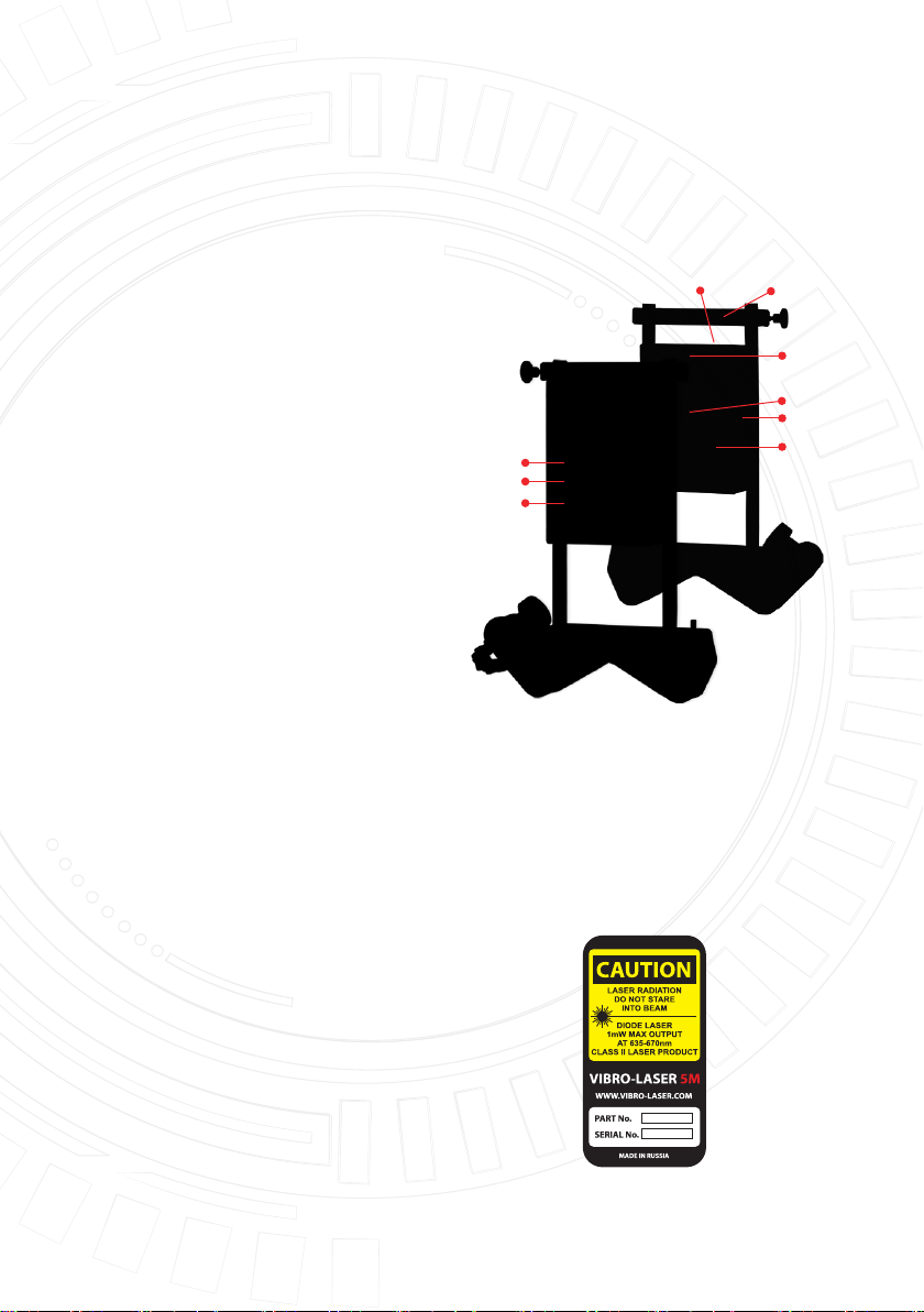
SYSTEM DESCRIPTION
SENSOR UNITS M and S
ON/OFF button (hold for 2-3
1
seconds to turn o)
Mini USB port (for charging)
2
3
Clamping bar with screw
4
Charge indicator (illuminates
green during charging then turns
o)
Connection indicator (illuminates
5
blue when connects, blinks during
transfer)
6
ON indicator (illuminates red when
ready for work, illuminates green
when ready for measurements)
7
Laser beam window
8
Detector receiver
9
4
5
6
3
7
8
2
1
Adjustment screw (for vertical laser positioning).
9
LABELING
Model, and Serial Number are printed on the
name plate on the back of sensor units.
9
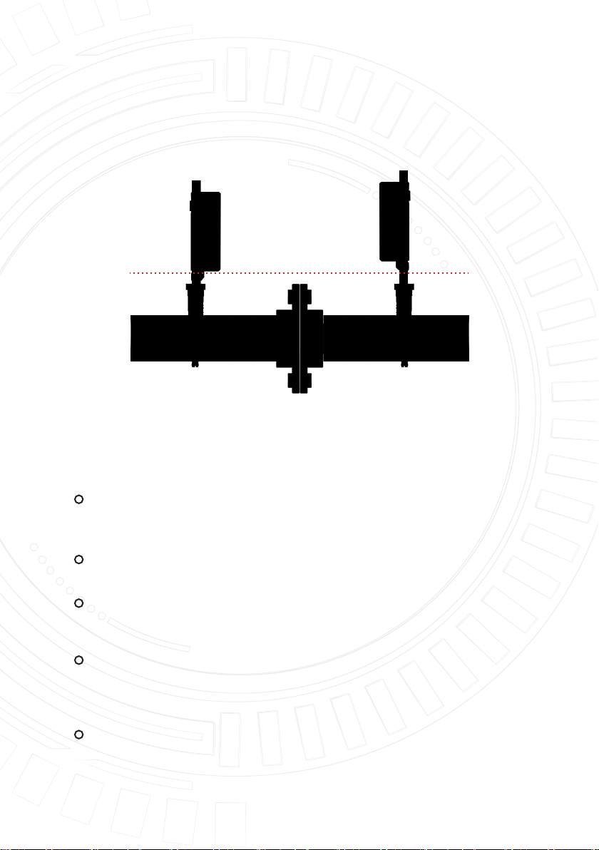
PREPARATION FOR WORK
Fix the sensor unit with the M label to the movable part of the machine, and
then x the S-labeled sensor unit to the stationary. Mounting each sensor for
each side as shown below.
The sensor units should be xed with a shift (see the gure).
Note!
Fix the sensors at a reasonable distance from eachother not beyond 10m
Place the v-bracket vertically on the shaft of the machine being
aligned. Take the loose end of the chain and pull it to remove the
whipping, then x it to the hook. (Fig. A)
Pull the chain tightly via the screw. Try to avoid excessive tightness.
(Fig. B)
If the shaft diameter is too big, use extension chains or replace with
common chains from any hardware store or industrial supplier to
make the chain longer. (Fig. C)
Correct the height of the units by slowly moving them along the bars
until the laser beam points to the center of the receiver of each unit.
Fix the units with the locking screw on the сlamping bar. (You can ne
tune the beams with the dial)
Clamping bars might be xed under units (recommended) as above
them. (Figг. D)
1010
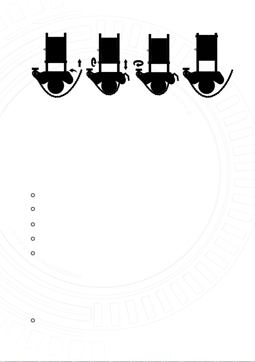
(Fig. A) (Fig. B) (Fig. C) (Fig. D)
Attention!
M unit laser direction can be adjusted with the adjusting screw at the top
of the unit. Normally, it is not required, but it may be needed if the distance
between units is large.
PRELIMINARY WORKS
Before start of the alignment check for following:
What are the alignment tolerances required?
Are there any thermal compensation requirements?
Are there any size restrictions for measurement system installation?
Are the shafts able to be rotated?
What size shims will be needed?
Before the installation of the measurement system to the machine, check its
base, bolts and preinstalled shims. Check for restrictions (is there enough
space for moving the machine).
After the visual check proceed with the following:
Remove old and rusty shims (if removable);
11

Check socket joint and loosen fasteners;
Check for soft foot;
Check how loose is the machine;
Check for run out of the shaft and the socket joint;
Check for pipe strain;
Check for end clearance between the shafts (axial alignment).
SETTINGS
Mount the sensor units on the shafts.
Turn the S and M units on (the red LED indicator goes on).
Turn the VIBRO-LASER software.
Touch the Icon “Global settings”
12

Touch the Icon “Sensor units search”
When connected, the indicators
will illuminate in blue.
Attention! After initial use the sensor units will be automatically
connected by default.
Choose Measurement Resolution.
Choose units of measurement (millimeters or
inches). Choose between metric and imperial
measurement convention, and the necessary
resolution (default setting is 0.01 mm or 0.4
mils).
Set the averaging lter from 1 to 20
Attention!
If laser beam passes through air with variable temperature or in the case of
signicant background noise, the beam directionality may be aected.
1
13

Variation of the results might be caused by instability of measurement
process. Try reducing the intensity of air movement between laser and the
detector (e.G. By replacing the heat sources or closing doors). If the results
are still instable, increase the lter value. Default setting is 1. Most
common values are from 1 to 3.
SENSOR UNIT READINGS
Start the program by touching the Icon
«Sensor Unit Readings» in the main menu
During the program loading the display shows data received directly from
the sensor units (position of the laser beam on the sensor and inclinometer
angle).
If no value is available, the display shows
To reset the readings touch the Icon
0
14

SOFT FOOT
Note!
Before any alignment the soft foot (loose t of the base) should be
addressed. Otherwise the results of a precision alignment will be
inneective. The removal of the soft foot is impossible without any
measuring devices. In your VIBRO-LASER embedded alignment program
you are able to provide to identify and correct soft foot.
Touch the Icon “Soft foot”
Before Soft Foot process you need to enter following dimensions: distance
between bars; distance between M unit and rst set of feet; distance
between the rst and the second sets of feet.
Set the units to the 12 o’clock (the green LED indicator of M and S units will
glow green).
Check bolt tensioning of each foot.
Touch the Icon “Next”
15

Choose the bolt by touching the Icon
First loosen the chosen bolt completely, then tighten it rmly. It is
recommended to use a torque wrench for tightening.
Save the measurement result by touching the “OK” Icon
Repeat these actions for other bolts.
Note!
You can carry out new measurement at any time by touching the
corresponding Icon.
To reset measurements touch the Icon
Values show shim plate thickness to eliminate the soft foot.
16

Make the required corrections then check each foot once more.
Note!
Allowed values from 0mm to 0.06 mm
17

HORIZONTAL ALIGNMENT
Touch the icon “Horizontal alignment”
in main men
Complete the alignment procedure step by step, following the arrow
indicator.
Note!
You can backup to the horizontal alignment menu anytime to conrm
your step.
18

Insert the tolerance values according to the rotation rate of the machine.
Touch the icon
Insert the dimensions
Touch the icon to insert the dimensions.
19

The eld activates a calculator interface. To submit the inserted dimensions,
touch ОК.
Use the supplied tape measure for measuring:
• Distance between the BARS CENTRES OF M and S UNITS
• Distance between the center of coupling joint and the BAR CENTER of M unit
• Distance between M unit and the rst set of feet (support).
• Distance between the rst and the second set of feet (support).
Touch the Icon
CARRY OUT MEASUREMENTS (9-3-12 METHOD)
This type of measurement requires rotating the shaft with the M and S units
in such a way that ag indicator on the information circle is in the green zone
(3-6-9-12o’clock).
Note!
For results please take measurements in at least three of four possible
control positions.
Set the M and S sensor units to the 9 o’clock green zone in such a way that
they have roughly the same angles (control the angles of M and S sensor
units via the virtual level).
20
Touch the Icon
The rst measurement is registered in the table.
To reset the data, touch the Icon
Turn the shafts to the 3 o’clock.
Tap the measurement icon
The second measurement is registered in the table.
Turn the shafts to the 12 o’clock
21

Touch the measurement icon
The third measurement is registered in the table.
Results of measurements
Touch the Icon
22

This screen shows the misalignment values according to the coupling joint
and the feet position (horizontal as well as vertical). Symbols on the left of the
value indicate angular and parallel misalignment and bias directions, as well
as indicates whether the values are within the allowable limits.
Within the tolerance limits (green)
Within the doubled tolerance limits (yellow)
Beyond the doubled tolerance limits (red)
Symbols next to the soupling joint REPEAT THE LIMIT READINGS.
Within the tolerance limits
Within the doubled tolerance limits
Beyond the doubled tolerance limits.
Note!.
The symbols above show whether the misalignment and bias values are
within the selected tolerances.
Touch the Icon
Live Alignment Mode
To adjust the shafts position vertically, rotate the shafts to 12 or 6 o’clock.
To set the M and S sensor units, use the displayed virtual levels. Adjust the
machine’s vertical position until the values are within the allowable limits.
Arrows next to the feet show the direction to move the machine in real time.
23

Note!
Use VIBRO-LASER SHIMS to align the machine vertically.
To adjust the shafts position horizontally, rotate the shafts to 3 or 9 o’clock.
Use the displayed virtual levels for precise alignment. Adjust the machine’s
horizontal position until the values are within the allowable limits according
to the arrows next to the feet.
Note!
First adjust the position of the machine vertically, then horizontally.
24

Note!
Tighten the foot bolts crosswise with same force using a calibrated torque
wrench to avoid changes of results!
The alignment is complete
To carry out
the verication measurements touch
Carry out the verication measurement using the Clock method.
After the verication measurement the Horizontal Alignment menu is opened.
Note!
To carry out more precise alignment after the verication measurement use the Live Alignment to continue align.
Save results, touch the Icon
CUT ANGLE METHOD
If 180 degree rotation of the shaft is impossible for some reason, please use
the CUT ANGLE METHOD.
The minimal rotation required is 40 degrees. The more rotation, the better
and more precise the alignment.
25

Touch the Icon
Start measuring from any point.
Rotate shafts in the next position according to the animation.
Touch the measurement Icon
The rst measurement is registered in the table.
Rotate shafts in the next position according to the animation.
26

Touch the Icon
The second measurement is registered in the table.
Rotate shafts in the next position according to the animation.
Touch the Icon
The third measurement is registered in the table.
Attention!
When taking measurements, rotate the shafts so the sectors do not
overlap each other
Note!
For the best accurate maintain the sensors with maximum distance.
Note!
When using this method the shafts should be connected to provide
maximum precision of the measurements and the alignment.
27

THERMAL EXPANSION CORRECTION
During the operation the equipment is exposed to various factors and forces.
The most common inuence on alignment is change of the machine
temperature which leads to the enlargement of a shaft and subsequent
misalignment. This process is called thermal expansion or growth.
To compensate the thermal expansion you need to make a correction for the
expansion of the cold machine during its heating through out operation.
Touch the icon in the alignment screen
Insert the correction via calculator
28

When the results are received, the sign is shown,
indicating that the thermal correction is made.
29

VERTICAL ALIGNMENT
Vertical shafts alignment is carried out by moving the machine
ange/coupling until the axes are coaxial enough to stay in the assigned limits.
The system is able to work with an allowance table.
Touch the Icon
Complete the alignment procedure step by step, following the arrow indicator.
Note!
You can open the vertical alignment menu at anytime to verify your step
30

Insert the tolerance values according to the RPM of the machine.
Touch the icon to insert the dimensions.
VThe eld activates a calculator interface. To submit the inserted dimensions,
touch ОК.
Use a measuring tape for measuring:
Distance between the BARS CENTERS OF M and S UNITS
Distance between the center of coupling joint and the BAR CENTER of
M unit
Distance between the centers of outer bolts.
Number of bolts (it is helpful to use a paint market or grease pencil to
mark the machine with the applicable bolt number for future
The vertical alignment program calculates the machine position by
measurements in three shaft positions when they are rotated 180°.
31

Touch the measurement icon
The rst measurement is registered in the table.
Rotate shafts in the next position according to the animation.
32

Touch the measurement icon
The second measurement is registered in the table.
Rotate shafts in the next position according to the animation.
Touch the measurement icon
The third measurement is registered in the table.
Touch the button
to get the measurement result
The measurement results screen shows the misalignment values according to
the coupling joint in both directions. Symbols on the left of the value stand
for parallel and angular directions and also indicates whether the values are
within the allowable limits.
33

The table on the right contains bolts numbers with designation of shims
required for eliminating misalignment.
within the allowable limits (green)
within the doubled allowable limits (yellow)
beyond the doubled allowable limits (red)
Symbols next to the socket joint repeat the limit readings.
within the allowable limits
within the doubled allowable limits
beyond the doubled allowable limits
Touch the button
to get the measurement result
34

To carry out the verication measurements
touch
Carry out the verication measurement.
After the verication measurement the Vertical Alignment menu is opened.
Save results by touching
35

SAVING DATA AND REPORT CREATION
Note!
The program has autosaving function: every time the program is started,
the previous result is shown.
To reset them, touch
One of our system advantages is possibility to save, restore and edit the
results of the alignment on any stage!
Touch the icon
to save alignment results
Insert the name of the report with the
virtual keyboard and touch
To cancel, touch
To upload the results touch
36

Note!
Upload a previously saved report and continue alignment from where you
stopped.
To create a report touch
You can edit the report header with your machine and company information
using the touch screen and virtual keyboard.
37

Options of report menu
Print the repor
Save the report as PDF
Save the report as PDF
38

INFORMATION ABOUT SYSTEM AND SOFTWARE
To see the system data, tap the button
i
Vibro-laser instruments corporation thanks you for your business.
Should you require support please go to www.Vibro-laser.Com
39


тм
тм
 Loading...