

Vibe SPACEBS4 -V1, DSPACEBB1-.V1, LITEBOX BASS 1 -V1, LITEBOX STERE0 2 -V1, LITEBOX STEREO 4 -V1 Owner's Manual

Power Amplifier
Instruction Manual
To ensure maximum performance and safety,
please follow this manual. Please retain the
manual for future reference after installation
Models: SPACEBS4 -V1
DSPACEBB1-V1
www.vibeaudio.co.uk

Attention
An aftermarket audio amplifier will place an additional load on the vehicles charging system, most modern vehicles have
sufficient capacity in the charging system as not all the electrical components of the vehicle will be switched on at once. Check
the fuse rating of the amplifier and use this as the peak current requirement, generally the continuous current draw will be a
third of the peak current, in other words an amplifier fused at 30 amps will have a continuous current draw of 10 amps when
playing music, however it may peak at 30 amps on occasions. Please check with the manufacturer as to whether your vehicle
can cope with the additional load of your amplifier, in some instances it may be necessary to upgrade the alternator and battery
or risk damage to the vehicles electrical system.
Congratulations on purchasing your VIBE
amplifier, please read this manual in order
to fully understand how to get the best
results from your amplifier and ensure
that all advice on how to look after the
amplifier is followed.
Thank you for buying VIBE, we hope you
enjoy listening to your product as much as
we enjoyed creating it.
VIBE R&D Division
OWNERS MANUAL
Mounting Guidelines
Your VIBE amplifier is designed with a swift installation routine in mind. Please mount the amplifier in a dry location on a solid
surface. NEVER mount the amplifier upside down, this will cause the amplifier to over heat and will eventually damage the
amplifier. Before fixing the amplifier in place please ensure that there is sufficient air flow around the exterior of the casing,
at least two inches is sufficient.
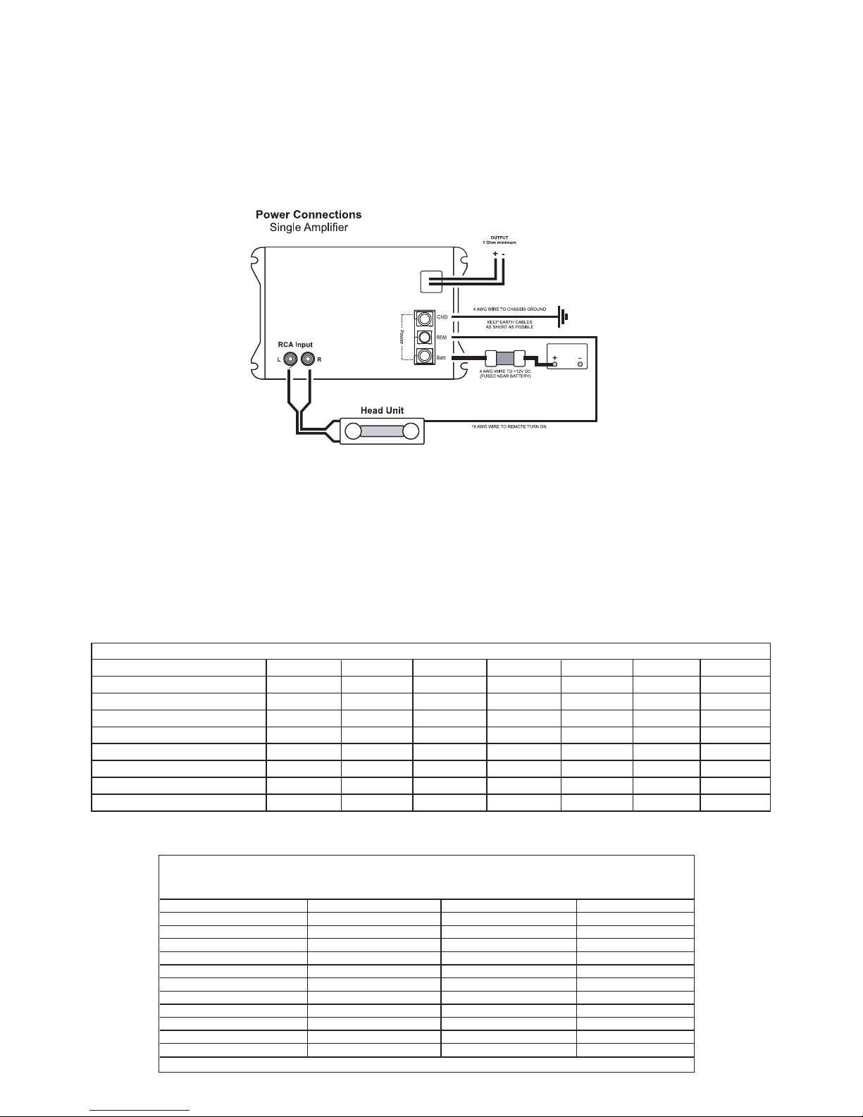
Connections
Power Cable
● At least 4 gauge cable (Deep SpaceBox Bass 1) 8 gauge cable ( SpaceBox Stereo 4) should be used for the
power connection to the amplifier.
● The power cable should be taken directly from the battery. Rubber grommets should be used when passing through
any bulkheads to prevent the cable from becoming chaffed or cut.
● It is vital that a fuse / circuit breaker (of at least equal value to the one fitted on the amplifier) is placed inline with the
power cable and is no further than eighteen inches away from the battery.
● Please ensure that the fuse is not fitted until the entire installation procedure is complete.
● The two tables below are to help you decide on what cable is correct for you. The first enables you to select the size of
cable depending on the length required. The second will help you convert the cable size from American Wire Gauge to
Metric and Imperial if you need to.
Length of Run
Current demand 0 – 4 Ft 4 – 7 Ft 7 – 10 Ft 10 – 13 Ft 13 – 16 Ft 16 – 19 Ft 19 – 22 Ft 22 – 28 Ft
0–20 amps 14 12 12 10 10 888
20–35 amps 12 10 886 664
35–50 amps 10 88 64 444
50–65 amps 886 44 442
65–85 amps 664 42 220
85–105 amps 664 22 220
105–125 amps 444 20 000
125–150 amps 222 00 000
AWG to Metric and Imperial Conversion Chart
cross sectional area
AWG Number Inch mm mm
2
0 0.325 8.25 53.5
1 0.289 7.35 42.4
2 0.258 6.54 33.6
3 0.229 5.83 26.7
4 0.204 5.19 21.1
5 0.182 4.62 16.8
6 0.162 4.11 13.3
7 0.144 3.66 10.5
8 0.128 3.26 8.36
9 0.114 2.91 6.63
10 0.102 2.59 5.26
Ground Cable
● At least 4 gauge cable (Deep SpaceBox Bass 1) 8 gauge cable ( SpaceBox Stereo 4) should be used for
the ground connection to the amplifier.
● The amplifier ground should be connected directly to the chassis of the vehicle, to bare metal.
● The cable length should be kept to an absolute minimum.
● It is not recommended that you connect the ground cable to the vehicles seatbelts anchor point.
Remote Turn On
● A minimum of 18 gauge cable should be used for this connection.
● The cable should be run with exactly the same care and attention as the power cable and taken back to the source
(headunit) and joined to the remote cable provided.
● If the source (headunit) does not have a remote turn on cable then a 12v supply should be used. This will require a
switch to be fitted inline to enable the amplifier to be turned on and off. Remember that if this switch is left on you will
flatten the car battery.
RCA Cables
● Depending on the model number of your amplifier and the number of speakers you wish to power you will have to run
either one or two RCA cables from the source to the amplifier.
● Please take extra care when running these cables from the source to the amplifier. Ensure that they are placed away
from all items that can generate any interference, wiring harnesses etc.
● It is recommended that the RCA cables should be run on opposite sides of the car to the previously installed power
cables if possible, to avoid the cable picking up interference.
12
3
47
8
5
6
9
10
11
12 1314
15
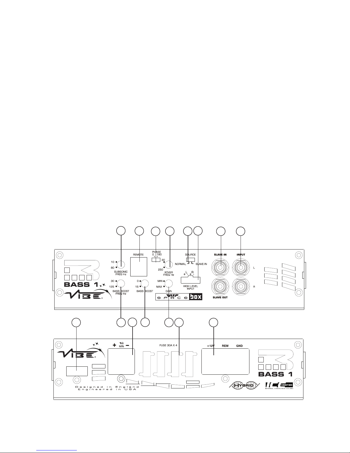
Terminals and controls : Deep SpaceBox Bass 1

1. Low level input
For connection to any source (head unit) with a low level output. This is your RCA output from the source (headunit)
2. Slave input / output
RCA input and output Connections used for amplifier strapping
3. High level input
To be used when no RCA's are available. Use the provided loom and connect to the closest speaker. The loom connector will only fit one
way around. Once plugged in you should connect the wires as below:
Left Positive – L+ white Right Positive - R+ Grey
Left Negative - L- white / Black Right Negative - R- Grey / Black
4. Gain control
Used to match the input signal of the source to the amplifier. See the setup section for more details.
5. Subsonic filter control
This control allows the subsonic filter frequency to be set, the filter is adjustable from 10Hz to 80 Hz
6. Crossover frequency control
This control is used to set the crossover point for the amplifier.
The frequency ranges on the low pass filter are from 30 Hz to 250 Hz,
7. Bass boost frequency control
This control sets the frequency that will be boosted by the bass boost control, the frequency ranges from 30Hz to 125Hz
8. Bass boost control
This control provides up to an extra +15 dB of bass boost at the chosen frequency. Use this boost to increase bass output from the
amplifier.
9. Phase switch
This allows the phase of the amplifier to be set to 0 or 180 degrees, one setting will make the bass from the subwoofer sound more in
time with the front speakers.
10. Source switch
This switch is set according to amplifier application, in normal operation it should be set to NORMAL and if the amplifier is acting as a
slave in a strapped configuration it should be set to SLAVE IN.
11. Gain remote Input Jack
Use to plug in the remote supplied bass level controller BBR1.
12. Indicator LED
When the amplifier is operating correctly the LED will flash 3
times and then illuminate constant red.
When the amplifier is in protection mode the LED will flash to
indicate protection condition - see table for fault code diagnosis.
13. Power connections
See Connections section for details on correct connections.
14. Fuses
Please ensure the following fuse rating is used when replacing fuses: 30 amp x 4
15. Speaker terminal output
For connection to the speakers. See Application section for wiring examples.

Set Up Section
To correctly set the gain control of the amplifier to match that of the source (headunit) use the following setup routine:
Turn the gain control to minimum on the amplifier.
Ensure the bass boost is set to 0 dB.
On the headunit set all crossovers ( if applicable) to flat and both bass and treble to zero.
Turn up the source (headunit) to approx 3/4 volume.
Very slowly turn up the gain on the amplifier until distortion can be heard in any of the speakers or until the volume reaches
an uncomfortable listening level when this is reached turn down the gain control slightly.
The gain control is now set.
The setting of the crossover will depend on what kind of speaker you are installing.
For a subwoofer it is recommended that the crossover is set to Low Pass and the frequency is set to match that of the
speakers specifications, or your preferred frequency - this is usally about 60 - 120
For a pair of full range speakers it is recommended that the crossover is set to Flat. The two frequency controls will then
have no effect on the amplifiers output and the speaker will receive a full range signal. However, using the high pass
crossovers will allow more control of your speakers. By removing the bass (low frequencies) the speakers can perform at
higher volumes with less distortion.
Note:
By using the crossovers correctly you will not only lengthen the life of your speakers but you will also get better performance
from them. To optimise your setup seek the advise of a professional installation engineer or visit your local VIBE audio dealer.
Amp strapping
The VIBE Deep SpaceBox Bass 1 amplifier is capable of being strapped together to deliver the combined output of both amplifiers into
a single channel.
NOTE: only identical amplifiers may be strapped together.
Strapping procedure
· Connect the RCA input from the source unit to the left and right RCA input of the master amplifier.
· Connect a mono RCA lead between the SLAVE OUT output of the master amplifier and the SLAVE IN input
· Set the source switch of the master amplifier to normal
· Set the source switch of the slave amplifier to slave in
· Set the phase switch of the master amplifier to 0 degrees
· Set the phase switch of the slave amplifier to 180 degrees
· Connect speaker cable between the negative speaker output of the master amp and the negative speaker output of the slave
amplifier. The cable must be of the same gauge you will be using to connect the amplifiers to the subwoofer
· The master positive speaker output is to be connected to the subwoofer positive terminal
· The slave positive speaker output is to be connected to the subwoofer negative terminal
 Loading...