

Vibe Slick a7 Owner's Manual

Instruction Manual
To ensure maximum performance and safety,
please follow this manual. Please retain the
manual for future reference after installation

CONTENTS
Mounting Guidelines.............................. 4
Connections........................................... 4
Setup Section........................................ 5,6
Applications............................................ 7,8
Trouble shooting.................................... 9
Specification........................................... 10
Warranty................................................. 10
Accessories............................................ 11
OWNERS MANUAL
Thank you for purchasing this VIBE
amplifier. It will provide you with a
lifetime trouble free usage
providing you follow a few simple
guidelines.
Mounting Guidelines
Your VIBE amplifier is designed with a swift installation routine in mind. Please mount the amplifier in a dry location on a solid
surface. NEVER mount the amplifier upside down, this will cause the amplifier to over heat and will eventually damage the
amplifier. Before fixing the amplifier in place please ensure that there is sufficient air flow around the exterior of the casing,
at least two inches is sufficient.
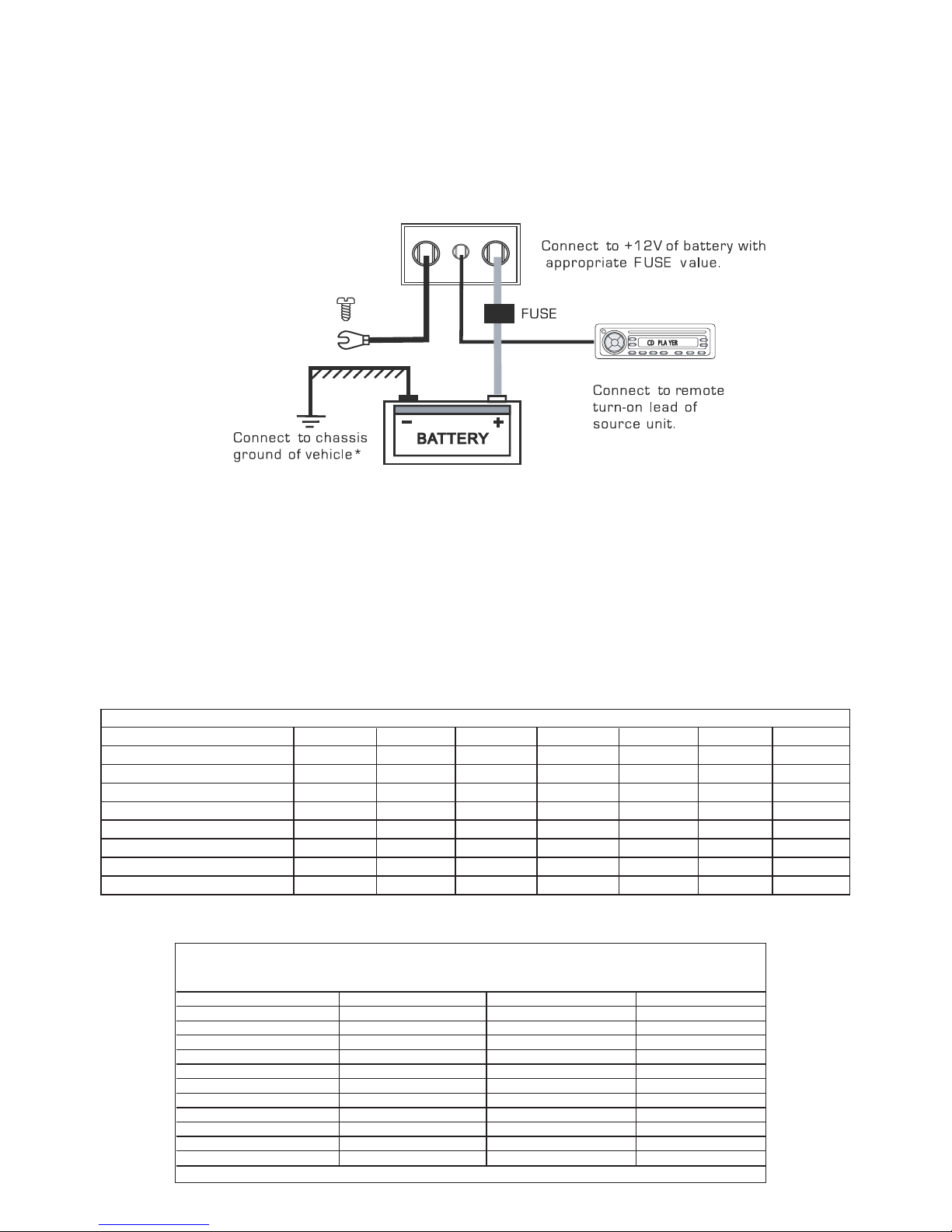
Connections
Power Cable
● At least an 8 gauge cable should be used for both the power and the ground connections to the amplifier.
● The power cable should be taken directly from the battery. Rubber grommets should be used when passing through
any bulkheads to prevent the cable from becoming chaffed or cut.
● It is vital that a fuse / circuit breaker (of at least equal value to the one fitted on the amplifier) is placed inline with the
power cable and is no further than eighteen inches away from the battery.
● Please ensure that the fuse is not fitted until the entire installation procedure is complete.
● The two tables below are to help you decide on what cable is correct for you. The first enables you to select the size of
cable depending on the length required. The second will help you convert the cable size from American Wire Gauge to
Metric if you need to.
Length of Run
Current demand 0 – 4 Ft 4 – 7 Ft 7 – 10 Ft 10 – 13 Ft 13 – 16 Ft 16 – 19 Ft 19 – 22 Ft 22 – 28 Ft
0–20 amps 14 12 12 10 10 8 8 8
20–35 amps 12 10 8 8 6 6 6 4
35–50 amps 10 8 8 6 4 4 4 4
50–65 amps 8 8 6 4 4 4 4 2
65–85 amps 6 6 4 4 2 2 2 0
85–105 amps 6 6 4 2 2 2 2 0
105–125 amps 4 4 4 2 0 0 0 0
125–150 amps 2 2 2 0 0 0 0 0
AWG to Metric Conversion Chart
cross sectional area
AWG Number Inch mm mm
2
0 0.325 8.25 53.5
1 0.289 7.35 42.4
2 0.258 6.54 33.6
3 0.229 5.83 26.7
4 0.204 5.19 21.1
5 0.182 4.62 16.8
6 0.162 4.11 13.3
7 0.144 3.66 10.5
8 0.128 3.26 8.36
9 0.114 2.91 6.63
10 0.102 2.59 5.26
Ground Cable
● The ground cable needs to carry the same current as the power cable. At least an 8 gauge cable should be used.
● The amplifier ground should be connected directly to the chassis of the vehicle, to bare metal.
● The cable length should be kept to an absolute minimum.
● It is not recommended that you connect the ground cable to the vehicles seatbelts anchor point.
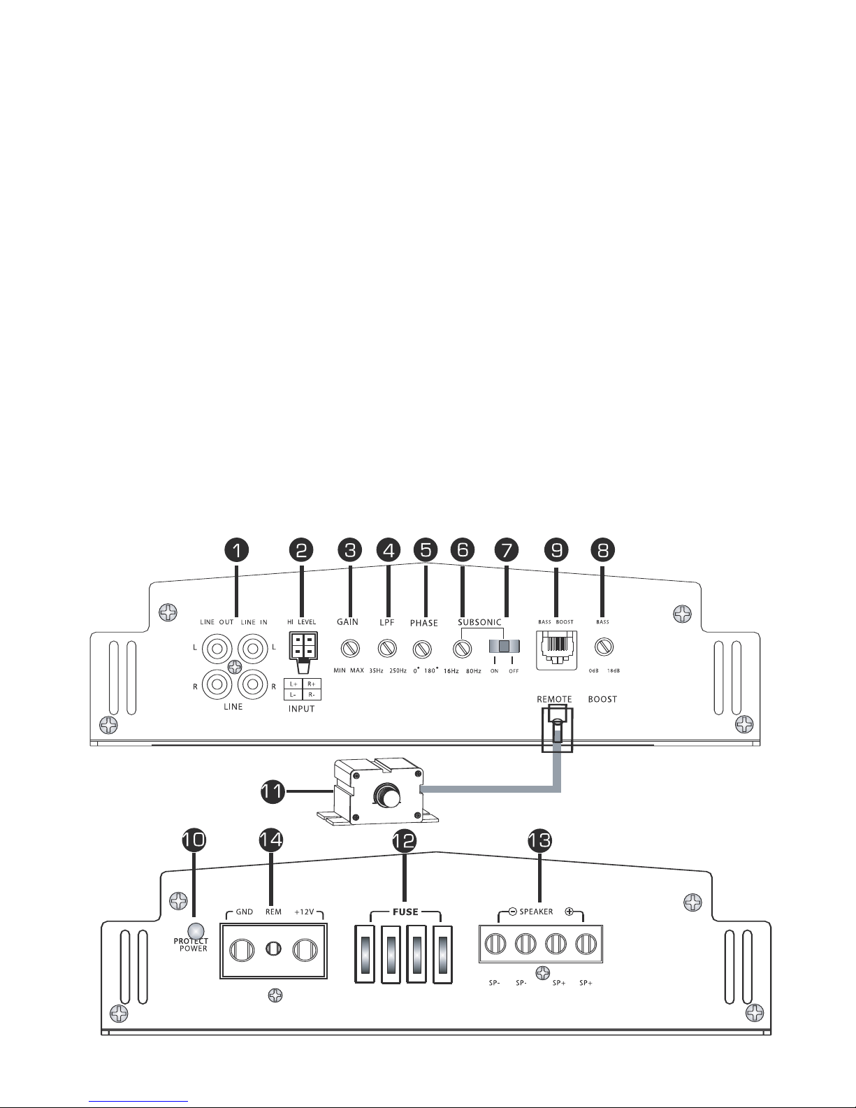
Remote Turn On
● A minimum of 18 gauge cable should be used for this connection.
● The cable should be run with exactly the same care and attention as the power cable and taken back to the source
(headunit) and joined to the remote cable provided.
● If the source (headunit) does not have a remote turn on cable then a 12v supply should be used. This will require a
switch to be fitted inline to enable the amplifier to be turned on and off. Remember that if this switch is left on you will
flatten the car battery.
RCA Cables
● Depending on the model number of your amplifier and the number of speakers you wish to power you will have to run
either one or two RCA cables from the source to the amplifier.
● Please take extra care when running these cables from the source to the amplifier. Ensure that they are placed away
from all items that can generate any interference, wiring harnesses etc.
● It is recommended that the RCA cables should be run on opposite sides of the car to the previously installed power
cables, if possible.
 Loading...