

Viavi Xgig1000 Hardware Manual

Xgig1000
Hardware Guide


Xgig1000
Hardware Guide
Viavi Solutions
1-844-GO-VIAVI
www.viavisolutions.com

Notice
Every effort was made to ensure that the information in this manual was accurate at the
time of printing. However, information is subject to change without notice, and Viavi
reserves the right to provide an addendum to this manual with information not available at
the time that this manual was created.
Copyright/Trademarks
© Copyright 2017 Viavi Solutions Inc. All rights reserved. No part of this guide may be
reproduced or transmitted, electronically or otherwise, without written permission of the
publisher. Viavi Solutions and the Viavi logo are trademarks of V iavi Solutions Inc. (“Viavi
”).
All other trademarks and registered trademarks are the property of their respective
owners.
Copyright release
Reproduction and distribution of this guide is authorized for US Government purposes
only.
Terms and conditions
Specifications, terms, and conditions are subject to change without notice. The provision
of hardware, services, and/or software are subject to Viavi’s standard terms and conditions, available at www.viavisolutions.com/en/terms-and-conditions.
Federal Communications Commission (FCC) Notice
This product was tested and found to comply with the limits for a Class A digital device,
pursuant to Part 15 of the FCC Rules. These limits are designed to provide reasonable
protection against harmful interference when the equipment is operated in a commercial
environment. This product generates, uses, and can radia te ra dio frequency energy and,
if not installed and used in accordance with the instruction manual, may cause harmful
interference to radio communications. Operation of this product in a residential area is
likely to cause harmful interference, in which case you will be required to co rrect the interference at your own expense.
The authority to operate this product is conditioned by the requirements that no modifications be made to the equipment unless the changes or modifications are expressly
approved by Viavi.
Page ii Xgig1000 Hardware Guide March 2017

WEEE and Battery Directive Compliance
Viavi has established processes in compliance with the Waste Electrical and Electronic
Equipment (WEEE) Directive, 2002/96/EC, and the Battery Directive, 2006/66/EC.
This product, and the batteries used to power the product, should not be disposed of as
unsorted municipal waste and should be collected separately and disposed of according
to your national regulations. In the European Union, all equipment and batteries purchased
from Viavi after 2005-08-13 can be returned for disposal at the end of its useful life. Viavi
will ensure that all waste equipment and batteries returned are reused, recycled, or
disposed of in an environmentally friendly manner, and in compliance with all applicable
national and international waste legislation.
It is the responsibility of the equipment owner to return equipment and batteries to Via vi for
appropriate disposal. If the equipment or battery was imported by a reseller whose name
or logo is marked on the equipment or battery , then the owner should return the equipme nt
or battery directly to the reseller.
Instructions for returning waste equipment and batteries to Viavi can be found in the Environmental section of Viavi’s web site at www.viavisolutions.com. If you have questions
concerning disposal of your equipment or batteries, contact Viavi’s WEEE Program
Management team.
March 2017 Xgig1000 Hardware Guide Page iii

Page iv Xgig1000 Hardware Guide March 2017

Contents
About This Guide
Purpose and Scope. . . . . . . . . . . . . . . . . . . . . . . . . . . . . . . . . . . . . . . . . . . . . . . . . . . . . . . . . . . . . x
Assumptions. . . . . . . . . . . . . . . . . . . . . . . . . . . . . . . . . . . . . . . . . . . . . . . . . . . . . . . . . . . . . . . . . . . x
What this Guide Contains . . . . . . . . . . . . . . . . . . . . . . . . . . . . . . . . . . . . . . . . . . . . . . . . . . . . . . x
Safety and Compliance Information . . . . . . . . . . . . . . . . . . . . . . . . . . . . . . . . . . . . . . . . . . . xi
Conventions . . . . . . . . . . . . . . . . . . . . . . . . . . . . . . . . . . . . . . . . . . . . . . . . . . . . . . . . . . . . . . . . . . xii
Technical Assistance. . . . . . . . . . . . . . . . . . . . . . . . . . . . . . . . . . . . . . . . . . . . . . . . . . . . . . . . . . xiv
Chapter 1 Xgig1000 System Overview
Xgig1000 Systems . . . . . . . . . . . . . . . . . . . . . . . . . . . . . . . . . . . . . . . . . . . . . . . . . . . . . . . . . . . . . 2
Xgig1000 12G SAS Chassis . . . . . . . . . . . . . . . . . . . . . . . . . . . . . . . . . . . . . . . . . . . . . . . . . . . . . . 2
12G SAS System Ports/Connections/Front Panel Reset Button . . . . . . . . . . . . . . . . 4
12G SAS System/Port Indicators . . . . . . . . . . . . . . . . . . . . . . . . . . . . . . . . . . . . . . . . . . . . . 6
12G SAS System Specifications . . . . . . . . . . . . . . . . . . . . . . . . . . . . . . . . . . . . . . . . . . . . . . 8
Xgig1000 4 Port 10G/16G Chassis . . . . . . . . . . . . . . . . . . . . . . . . . . . . . . . . . . . . . . . . . . . . . . 11
4 Port 10G/16G System Ports/Connections/Front Panel Reset Button . . . . . . . . 13
4 Port 10G/16G System/Port Indicators . . . . . . . . . . . . . . . . . . . . . . . . . . . . . . . . . . . . . 15
Port 10G/16G System Specifications . . . . . . . . . . . . . . . . . . . . . . . . . . . . . . . . . . . . . . . . 17
Xgig1000 8 Port 10G/16G Chassis . . . . . . . . . . . . . . . . . . . . . . . . . . . . . . . . . . . . . . . . . . . . . . 20
8 Port 10G/16G System Ports/Connections/Front Panel Reset Button . . . . . . . . 22
8 Port 10G/16G System/Port Indicators . . . . . . . . . . . . . . . . . . . . . . . . . . . . . . . . . . . . . 24
8 Port 10G/16G System Specifications . . . . . . . . . . . . . . . . . . . . . . . . . . . . . . . . . . . . . . 26
Xgig1000 8+2 Port 10G/16G/40G Chassis . . . . . . . . . . . . . . . . . . . . . . . . . . . . . . . . . . . . . . .29
8+2 Port 10G/16G/40G System Ports/Connections/Front Panel Reset Button . 31
8+2 Port 10G/16G/40G System/Port Indicators . . . . . . . . . . . . . . . . . . . . . . . . . . . . . . 33
8+2 Port 10G/16G/40G System Specifications . . . . . . . . . . . . . . . . . . . . . . . . . . . . . . . 35
Xgig1000 2 Port 10G/40G Chassis . . . . . . . . . . . . . . . . . . . . . . . . . . . . . . . . . . . . . . . . . . . . . . 38
2 Port 10G/40G System Ports/Connections/Front Panel Reset Button . . . . . . . .40
2 Port 10G/40G System/Port Indicators . . . . . . . . . . . . . . . . . . . . . . . . . . . . . . . . . . . . . 43
ix
1
March 2017 Xgig1000 Hardware Guide Page v

Contents
2 Port 10G/40G System Specifications . . . . . . . . . . . . . . . . . . . . . . . . . . . . . . . . . . . . . 45
Xgig1000 PCIe Chassis. . . . . . . . . . . . . . . . . . . . . . . . . . . . . . . . . . . . . . . . . . . . . . . . . . . . . . . . .47
PCIe System Ports/Connections/Front Panel Reset Button . . . . . . . . . . . . . . . . . . 49
PCIe System/Port Indicators . . . . . . . . . . . . . . . . . . . . . . . . . . . . . . . . . . . . . . . . . . . . . . . . 51
PCIe System Specifications . . . . . . . . . . . . . . . . . . . . . . . . . . . . . . . . . . . . . . . . . . . . . . . . .53
Xgig1000 4 Port 25G/32G Chassis . . . . . . . . . . . . . . . . . . . . . . . . . . . . . . . . . . . . . . . . . . . . . .55
4 Port 25G/32G System Ports/Connections/Front Panel Reset Button. . . . . . . . .57
4 Port 25G/32G System/Port Indicators . . . . . . . . . . . . . . . . . . . . . . . . . . . . . . . . . . . . 59
4 Port 25G/32G System Specifications . . . . . . . . . . . . . . . . . . . . . . . . . . . . . . . . . . . . . .61
Xgig1000 8 Port 25G/32G Chassis . . . . . . . . . . . . . . . . . . . . . . . . . . . . . . . . . . . . . . . . . . . . . 63
8 Port 25G/32G System Ports/Connections/Front Panel Reset Button . . . . . . . 65
8 Port 25G/32G System/Port Indicators . . . . . . . . . . . . . . . . . . . . . . . . . . . . . . . . . . . . 67
8 Port 25G/32G System Specifications . . . . . . . . . . . . . . . . . . . . . . . . . . . . . . . . . . . . . 69
Xgig1000 10 Port 25G/32G/50G/100G/128G Chassis . . . . . . . . . . . . . . . . . . . . . . . . . . . . . 71
10 Port 25G/32G/50G/100G/128G System Ports/Connections/Front Panel Reset
Button
. . . . . . . . . . . . . . . . . . . . . . . . . . . . . . . . . . . . . . . . . . . . . . . . . . . . . . . . . . . . . . . . . . . .73
10 Port 25G/32G/50G/100G/128G System/Port Indicators . . . . . . . . . . . . . . . . . . . .75
10 Port 25G/32G/50G/100G/128G System Specifications . . . . . . . . . . . . . . . . . . . . .77
Chapter 2 Xgig1000 System Setup
Unpacking the System. . . . . . . . . . . . . . . . . . . . . . . . . . . . . . . . . . . . . . . . . . . . . . . . . . . . . . . . 80
Locating the System in Your Environment . . . . . . . . . . . . . . . . . . . . . . . . . . . . . . . . . . . . . 80
Rack Mounting Instructions . . . . . . . . . . . . . . . . . . . . . . . . . . . . . . . . . . . . . . . . . . . . . . . .81
Safety Protocol for Rack Mounting . . . . . . . . . . . . . . . . . . . . . . . . . . . . . . . . . . . . . . . . .81
Xgig1000 System Overview . . . . . . . . . . . . . . . . . . . . . . . . . . . . . . . . . . . . . . . . . . . . . . . . . . . 82
Xgig1000 System and Application Images . . . . . . . . . . . . . . . . . . . . . . . . . . . . . . . . 84
Xgig1000 Server Software. . . . . . . . . . . . . . . . . . . . . . . . . . . . . . . . . . . . . . . . . . . . . . . . . 84
Xgig Client Software . . . . . . . . . . . . . . . . . . . . . . . . . . . . . . . . . . . . . . . . . . . . . . . . . . . . . . 85
Xgig Access Through a Firewall . . . . . . . . . . . . . . . . . . . . . . . . . . . . . . . . . . . . . . . . . . . . 85
Setup Instructions. . . . . . . . . . . . . . . . . . . . . . . . . . . . . . . . . . . . . . . . . . . . . . . . . . . . . . . . . . . . 86
PATH 1: Setting Up the Xgig1000 Chassis in a DHCP Network . . . . . . . . . . . . . . . 86
PATH 2: Setting Up the Xgig1000 Chassis with a Static IP Address in a Non-DHCP
Network
PATH 3: Setting Up the Xgig1000 Chassis in a Standalone Environment . . . . . 90
PATH 4: Setting Up the Xgig1000 Chassis using USB Direct Connect. . . . . . . . . 94
Cascading Xgig1000 chassis. . . . . . . . . . . . . . . . . . . . . . . . . . . . . . . . . . . . . . . . . . . . . . . . . . . 95
Sync Discovery Process . . . . . . . . . . . . . . . . . . . . . . . . . . . . . . . . . . . . . . . . . . . . . . . . . . . . . . . .97
Xgig1000 Chassis Startup Sequence . . . . . . . . . . . . . . . . . . . . . . . . . . . . . . . . . . . . . . . . . . . 98
Xgig1000 Chassis Shutdown Sequence . . . . . . . . . . . . . . . . . . . . . . . . . . . . . . . . . . . . . . . . 99
Shutdown Using the Web Utility Interface . . . . . . . . . . . . . . . . . . . . . . . . . . . . . . . . . 99
Shutdown Using the Console Interface. . . . . . . . . . . . . . . . . . . . . . . . . . . . . . . . . . . . . 99
Shutdown Using Xgig Application . . . . . . . . . . . . . . . . . . . . . . . . . . . . . . . . . . . . . . . . 100
. . . . . . . . . . . . . . . . . . . . . . . . . . . . . . . . . . . . . . . . . . . . . . . . . . . . . . . . . . . . . . . . . 87
79
Page vi Xgig1000 Hardware Guide March 2017

Contents
Chapter 3 Administration
Administration of the Xgig1000 System over the Internet . . . . . . . . . . . . . . . . . . . . . 102
Xgig Web Utility. . . . . . . . . . . . . . . . . . . . . . . . . . . . . . . . . . . . . . . . . . . . . . . . . . . . . . . . . . 102
Accessing the Xgig1000 System for Administration . . . . . . . . . . . . . . . . . . . . . . . . 103
System Requirements for Internet Administration . . . . . . . . . . . . . . . . . . . . . . . . . 104
Setting Client Authentication. . . . . . . . . . . . . . . . . . . . . . . . . . . . . . . . . . . . . . . . . . . . . . . . . 105
Remote Administration of the Xgig1000 System via USB . . . . . . . . . . . . . . . . . . . . . . 106
Chassis Configuration Dialog Box . . . . . . . . . . . . . . . . . . . . . . . . . . . . . . . . . . . . . . . . . 106
Blade License Configuration. . . . . . . . . . . . . . . . . . . . . . . . . . . . . . . . . . . . . . . . . . . . . . . 107
Utilities . . . . . . . . . . . . . . . . . . . . . . . . . . . . . . . . . . . . . . . . . . . . . . . . . . . . . . . . . . . . . . . . . . 115
Run a Test . . . . . . . . . . . . . . . . . . . . . . . . . . . . . . . . . . . . . . . . . . . . . . . . . . . . . . . . . . . . . . . . 116
Operating System Support. . . . . . . . . . . . . . . . . . . . . . . . . . . . . . . . . . . . . . . . . . . . . . . . 117
How To Uninstall or Re-install the Xgig USB Device Driver . . . . . . . . . . . . . . . . . 118
Licensing . . . . . . . . . . . . . . . . . . . . . . . . . . . . . . . . . . . . . . . . . . . . . . . . . . . . . . . . . . . . . . . . . . . . 119
System Upgrades . . . . . . . . . . . . . . . . . . . . . . . . . . . . . . . . . . . . . . . . . . . . . . . . . . . . . . . . . . . . 121
Setting Up the FTP Site for Upgrades . . . . . . . . . . . . . . . . . . . . . . . . . . . . . . . . . . . . . 121
Updating the FTP Server with Upgrade Images . . . . . . . . . . . . . . . . . . . . . . . . . . . . 123
Upgrading the Xgig1000 System Image and Application Image Software . . . 124
Chapter 4 Tips and Troubleshooting
101
129
Tro ubles hooti ng . . . . . . . . . . . . . . . . . . . . . . . . . . . . . . . . . . . . . . . . . . . . . . . . . . . . . . . . . . . . . 130
Power up problems following chassis shutdown . . . . . . . . . . . . . . . . . . . . . . . . . . . 130
Cannot ping the Xgig1000 chassis . . . . . . . . . . . . . . . . . . . . . . . . . . . . . . . . . . . . . . . . . 130
Cannot connect to the Xgig1000 chassis using the web browser. . . . . . . . . . . . 131
Can’t find the system or application upgrade on FTP server . . . . . . . . . . . . . . . . 131
The system is rebooting repeatedly . . . . . . . . . . . . . . . . . . . . . . . . . . . . . . . . . . . . . . . 132
The Cascade Port LEDs do not blink after initiating Sync Discovery . . . . . . . . . 132
Sync Discovery does not complete . . . . . . . . . . . . . . . . . . . . . . . . . . . . . . . . . . . . . . . . 132
Cannot find an Xgig1000 chassis using the discover button
in the port selection window
. . . . . . . . . . . . . . . . . . . . . . . . . . . . . . . . . . . . . . . . . . . . . . 133
Restarting the Xgig1000 Chassis with the Backup System Image Using USB
System Recovery Drive
. . . . . . . . . . . . . . . . . . . . . . . . . . . . . . . . . . . . . . . . . . . . . . . . . . . . . . . 133
Tips . . . . . . . . . . . . . . . . . . . . . . . . . . . . . . . . . . . . . . . . . . . . . . . . . . . . . . . . . . . . . . . . . . . . . . . . . 135
Pinging the Xgig1000 Chassis . . . . . . . . . . . . . . . . . . . . . . . . . . . . . . . . . . . . . . . . . . . . . 135
Naming the Xgig1000 Chassis . . . . . . . . . . . . . . . . . . . . . . . . . . . . . . . . . . . . . . . . . . . . . 135
Using Wireless Connections . . . . . . . . . . . . . . . . . . . . . . . . . . . . . . . . . . . . . . . . . . . . . . . 135
Network Bandwidth Considerations. . . . . . . . . . . . . . . . . . . . . . . . . . . . . . . . . . . . . . . 135
Recommended System for More than 16 Ports . . . . . . . . . . . . . . . . . . . . . . . . . . . . . 136
Appendix A Accessories for the Xgig1000 System
Analog Passthrough Adapters . . . . . . . . . . . . . . . . . . . . . . . . . . . . . . . . . . . . . . . . . . . . . . . . 138
Analog Passthrough Adapters for SFP Connectors . . . . . . . . . . . . . . . . . . . . . . . . . . 138
Quad Analog Passthrough (QAPT) Adapter for QSFP Connectors . . . . . . . . . . . . 139
Connecting the Analog Passthrough Adapters . . . . . . . . . . . . . . . . . . . . . . . . . . . . . 140
137
March 2017 Xgig1000 Hardware Guide Page vii

Contents
Appendix B Tips and Troubleshooting for
First Generation Chassis
Tro ubles hooti ng . . . . . . . . . . . . . . . . . . . . . . . . . . . . . . . . . . . . . . . . . . . . . . . . . . . . . . . . . . . . . .144
Power up problems following chassis shutdown . . . . . . . . . . . . . . . . . . . . . . . . . . .144
Cannot ping the Xgig1000 chassis . . . . . . . . . . . . . . . . . . . . . . . . . . . . . . . . . . . . . . . . .144
Cannot connect to the Xgig1000 chassis using the web browser . . . . . . . . . . . .145
Can’t find the system or application upgrade on FTP server . . . . . . . . . . . . . . . .145
The system is rebooting repeatedly. . . . . . . . . . . . . . . . . . . . . . . . . . . . . . . . . . . . . . . .146
The Cascade Port LEDs do not blink after initiating Sync Discovery . . . . . . . . .146
Sync Discovery does not complete. . . . . . . . . . . . . . . . . . . . . . . . . . . . . . . . . . . . . . . . .146
Cannot find an Xgig1000 chassis using the discover button in the port selection
window
Restarting the Xgig1000 Chassis with the Backup System Image. . . . . . . . . . . . . . .148
Tips . . . . . . . . . . . . . . . . . . . . . . . . . . . . . . . . . . . . . . . . . . . . . . . . . . . . . . . . . . . . . . . . . . . . . . . . . .149
Pinging the Xgig1000 Chassis . . . . . . . . . . . . . . . . . . . . . . . . . . . . . . . . . . . . . . . . . . . . .149
Naming the Xgig1000 Chassis . . . . . . . . . . . . . . . . . . . . . . . . . . . . . . . . . . . . . . . . . . . . .149
Using Wireless Connections . . . . . . . . . . . . . . . . . . . . . . . . . . . . . . . . . . . . . . . . . . . . . . .149
Network Bandwidth Considerations . . . . . . . . . . . . . . . . . . . . . . . . . . . . . . . . . . . . . . .149
Recommended System for More than 16 Ports . . . . . . . . . . . . . . . . . . . . . . . . . . . . .150
. . . . . . . . . . . . . . . . . . . . . . . . . . . . . . . . . . . . . . . . . . . . . . . . . . . . . . . . . . . . . . . . . . 147
143
Index
151
Page viii Xgig1000 Hardware Guide March 2017

About This Guide
• “Purpose and Scope” on page x
• “Assumptions” on page x
• “What this Guide Contains” on page x
• “Safety and Compliance Information” on page xi
• “Conventions” on page xii
• “Technical Assistance” on page xiv
March 2017 Xgig1000 Hardware Guide Page ix

About This Guide
Purpose and Scope
Purpose and Scope
The purpose of this guide is to help you successfully use the Xgig1000 features and capabilities. This guide includes task-based instructions that describe how to inst all, configure,
use, and troubleshoot the Xgig1000. Additionally, this guide provides a complete description of Viavi’s warranty, services, and repair information, including terms and conditions of
the licensing agreement.
Assumptions
This guide is intended for novice, intermediate, and experienced users who want to use
the Xgig1000 effectively and efficiently. We are assuming that you have basic computer
and mouse/track ball experience and are familiar with basic telecommunication co ncep ts
and terminology.
What this Guide Contains
The chapters contain the following information:
Chapter 1 “Xgig1000 System Overview” describes each of the Xgig1000 system chassis
in detail, including a description, an illustration, and a description of front and rear panel
ports, connectors, buttons, and indicators. System specifications are also included.
Chapter 2 “Xgig1000 System Setup” provides information on how to unpack and place
your system, how to set up your system, as well as discovery information and system
startup and shutdown sequences.
Chapter 3 “Administration” describes how to perform administrative tasks on your system,
as well as licensing and upgrades.
Chapter 4 “Tips and Troubleshooting” provides information on basic troubleshooting and
restarting your system from a recovery drive. Additional tips are also provided.
Appendix A “Accessories for the Xgig1000 System” describes additional accessories
provided with your system.
Appendix B “Tips and Troubleshooting for First Generation Chassis” provides informa-
tion on basic troubleshooting and restarting your system from a recovery drive if you have
a first generation chassis. Additional tips are also provided.
Page x Xgig1000 Hardware Guide March 2017
Safety and Compliance Information
Safety and compliance information for the instrument are provided in printed form and ship
with your instrument.
It is mandatory to permanently connect this device to the protective earth.
When powering this device, always use an AC power cable that includes an earth (safety)
ground connection.
WARNING
Do not attempt to service this product yourself, as opening or removing covers may
expose you to dangerous voltage and other hazards. Refer all servicing to qualified ser vice personnel.
CAUTION
This equipment contains parts and assemblies sensitive to electrostatic discharge
(ESD). Use ESD precautionary procedures when touching, removing, or inserting ESD
sensitive parts and assemblies, or damage to components could result.
Safety and Compliance Information
About This Guide
An electrostatic-sensitive device can only withstand voltage spikes of 10 to 100 volts.
Any discharge greater than this can damage or effectively destroy such a device while
going unnoticed by a technician. Common plastics (synthetic insulating materials),
clothing, and paper or cardboard are the most common source of static charges.
March 2017 Xgig1000 Hardware Guide Page xi

About This Guide
Conventions
Conventions
This guide uses typographical and symbols conventions as described in the following
tables.
Table 1 Text formatting and other typographical conventions
Item(s) Example(s)
Buttons, keys, or switches that
you press or flip on a physical
device.
Buttons, links, menus, menu
options, tabs, or fields on a PCbased or Web-based user interface that you click, select, or
type information into.
Directory names, file names,
and code and output messages
that appear in a command line
interface or in some graphical
user interfaces (GUIs).
Text you must type exactly as
shown into a command line
interface, text file, or a GUI text
field.
References to guides, books,
and other publications appear in
this typeface.
Press the On button.
– Press the Enter key.
– Flip the Power switch to the on position.
Click Start.
– Click File > Properties.
– Click the Properties tab.
– Type the na me of the probe in the Probe Name
field.
$NANGT_DATA_DIR/results (directory)
– test_products/users/
defaultUser.xml (file name)
– All results okay. (output message)
– Restart the applications on the server using the
following command:
$BASEDIR/startup/npiu_init restart
Type: a:\set.exe in the dialog box.
Refer to Newton’s Telecom Dictionary.
Command line option separa-
platform [a|b|e]
tors.
Optional arguments (text vari-
login [platform name]
ables in code).
Required arguments (text vari-
<password>
ables in code).
Table 2 Symbol conventions
This symbol indicates a note that includes important supplemental information or tips
related to the main text.
This symbol represents a general hazard. It may be associated with either a DANGER,
WARNING, or CAUTION message. See Table 3 for more information.
Page xii Xgig1000 Hardware Guide March 2017
About This Guide
Conventions
This symbol represents hazardous voltages. It may be associated with either a DANGER, WARNING, or CAUTION message. See Table 3 for more information.
This symbol represents a risk of explosion. It may be associated with either a DANGER,
WARNING, or CAUTION message. See Table 3 for more information.
This symbol, located on the equipment, battery, or the packaging indicates that the
equipment or battery must not be disposed of in a land-fill site or as municipal waste,
and should be disposed of according to your national regulations.
Table 3 Safety definitions
Term Definition
DANGER
Indicates a potentially hazardous situation that, if not avoided, will
result in death or serious injury. It may be associated with either a
general hazard, high voltage, or other symbol. See
Table 2 for more
information.
WARNING Indicates a potentially hazardous situation that, if not avoided, could
result in death or serious injury. It may be associated with either a
general hazard, high voltage, or other symbol. See
Table 2 for more
information.
CAUTION Indicates a potentially hazardous situation that, if not avoided, could
result in minor or moderate injury and/or damage to equipment.
It may be associated with either a general hazard, high voltage, or risk
of explosion symbol. See
Table 2 for more information.
When applied to software actions, indicates a situation that, if not
avoided, could result in loss of data or a disruption of software operation.
March 2017 Xgig1000 Hardware Guide Page xiii

About This Guide
Technical Assistance
Technical A ssi st a n ce
If you require technical assistance, call 1-844-GO-VIAVI (1-844-468-4284) or
e-mail
For the latest TAC information, go to
http://www.viavisolutions.com/en/services-and-support/support/technical-assistance
Techsupport-snt@viavisolutions.com.
.
Page xiv Xgig1000 Hardware Guide March 2017

Chapter1 Xgig1000 System Overview
This chapter provides a general description of the Xgig1000. Topics discussed in this
chapter include the following:
• “Xgig1000 Systems” on page 2
• “Xgig1000 12G SAS Chassis” on page 2
• “Xgig1000 4 Port 10G/16G Chassis” on page 11
• “Xgig1000 8 Port 10G/16G Chassis” on page 20
• “Xgig1000 8+2 Port 10G/16G/40G Chassis” on page 29
1
• “Xgig1000 2 Port 10G/40G Chassis” on page 38
• “Xgig1000 PCIe Chassis” on page 47
• “Xgig1000 4 Port 25G/32G Chassis” on page 55
• “Xgig1000 8 Port 25G/32G Chassis” on page 63
• “Xgig1000 10 Port 25G/32G/50G/100G/128G Chassis” on page 71
March 2017 Xgig1000 Hardware Guide Page 1
Chapter 1 Xgig1000 System Overview
Xgig1000 Systems
Xgig1000 Systems
The Xgig1000 Distributed Systems for Monitoring, Analysis, and Testing are multi-purpose
systems designed for product development, field service, and network operations
personnel. These chassis are bench setups but can be rack mounted. You can place them
at your data center or anywhere on your network. The Xgig1000 chassis can also be
directly connected to a PC to create a portable instrument for test or analysis.
The Xgig1000 systems can be accessed remotely using a LAN connection and software
to perform tasks. System administration and configuration can be performed over the
network.
NOTE
There are two generations of Xgig1000 chassis.
– The first generation does not have a power switch on the back of the chassis.
– The second generation has a power switch on the back of the chassis and comes
with a USB System Recovery Drive. This guide assumes you are using a second
generation chassis. Early versions of the second generation chassis require that
the Front Panel Reset button be pressed when the chassis is initially powered up.
However, later versio ns do not require the Front Panel Reset button to be pressed
when initially powered up.
The primary difference in the instructions is in the start up and shutdown sequences.
The troubleshooting chapter in this guide is designed for the new generation chassis
and includes instructions for the use of the USB System Recovery Drive.
Troubleshooting information for first generation chassis is located in the appendix.
Xgig1000 12G SAS Chassis
The Xgig1000 12G SAS is a fixed blade chassis that houses one Xgig 12G SAS blade with
8 ports (four links) that support the Analyzer, Generator, and Jammer functions in Analog
Passthrough mode only . Th e line rates supported are 3.0000, 6 .0000, and 12.0000 Gbp s.
This fixed-blade system does not require or accept Xgig or Xgig5000 blades. The 12G
SAS blade in the chassis is designed for use with the SAS-3 protocol. The 12G SAS blade
also supports the SATA protocol at 6.0000 Gbps and 3.0000 Gbps. Xgig provides the
necessary software tools running in a PC environment to perform the application task
using the blade fixed within the chassis.
The Xgig1000 12G SAS chassis is shown in Figure 1.
Page 2 Xgig1000 Hardware Guide March 2017
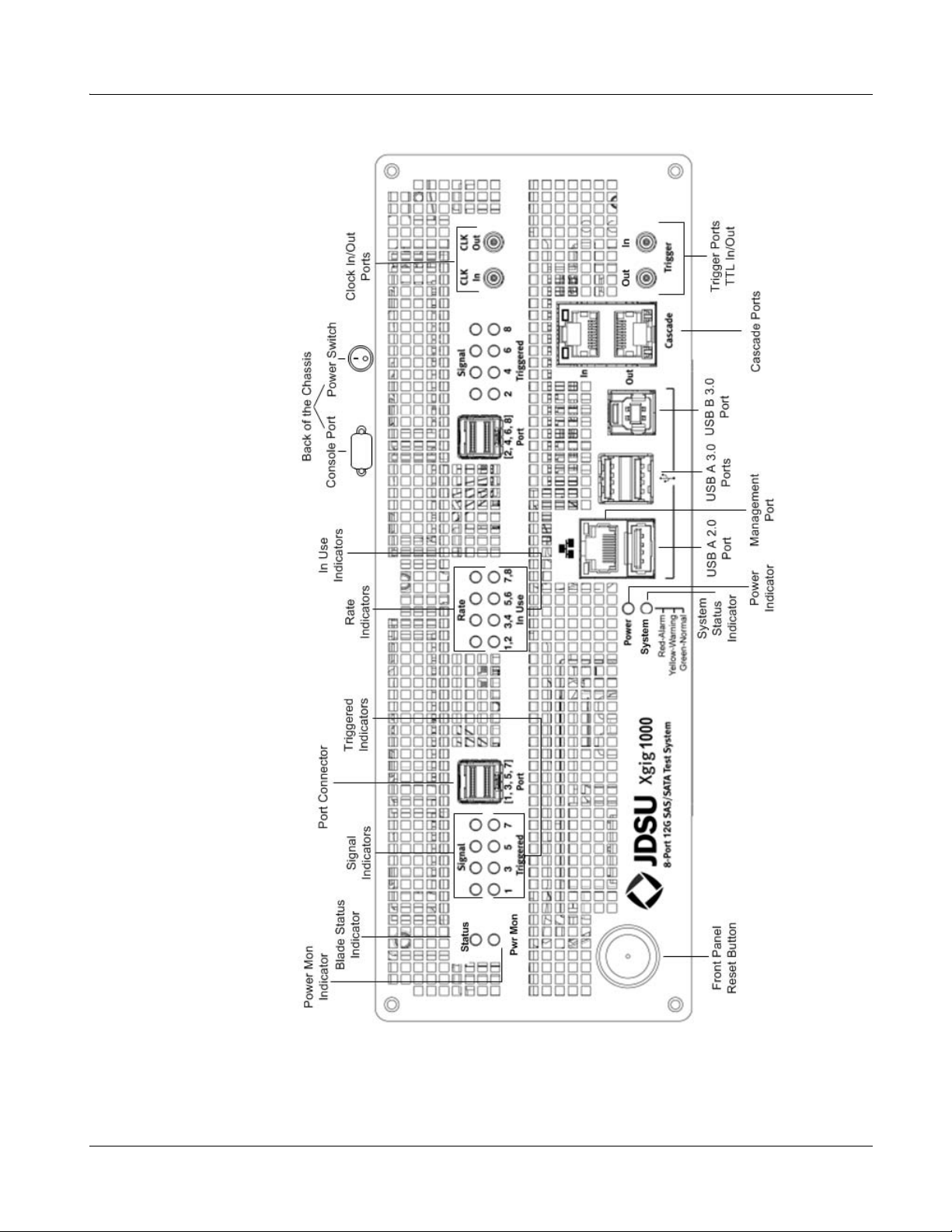
Figure 1 Xgig1000 12G SAS Chassis
Chapter 1 Xgig1000 System Overview
Xgig1000 12G SAS Chassis
March 2017 Xgig1000 Hardware Guide Page 3

Chapter 1 Xgig1000 System Overview
Xgig1000 12G SAS Chassis
12G SAS System Ports/Connections/Front Panel Reset Button
Management Port
The Management port provides a connection to the 10/100/1000 network or a direct
connection to a PC's 10/100/1000 Ethernet adapter . The Management port is used for the
following:
• Configuring the Xgig1000 chassis using the Xgig Web Utility
• Controlling the operation of Xgig application-specific blades
• Retrieving data collected by Xgig application-specific blades
Console Port
The Console port is a 9-pin serial port on the back of the chassis. The Console port is used
for the following:
• Configuring the Xgig1000 chassis
• Minor troubleshooting
• Selecting the Xgig1000 boot image (this functionality is not available through the
Console port for second generation chassis. Instead, these chassis use the USB
system recovery drive.)
• Basic administration
The Console port can be used for all system configuration through a command line inter-
face. Configuration commands are passed to Xgig by connecting the Console port to a
terminal or to a PC with a terminal emulation program using a cross-over cable. However ,
configuration is usually performed using the Xgig Web Utility over the internet throug h the
10/100/1000 Ethernet management port.
Trigger/TTL Ports
The TTL Input and TTL Output ports provide a means of sending or receiving an electrical
signal between the Xgig and other instruments for triggering purposes.
The trigger-out pulse is approximately 200ns wide, active-high, L VTTL (3. 3V). The triggerin can handle 3.3V or 5.0V inputs, also active-high. Use 50 ohm cables with these ports.
Cascade Ports
The Cascade In and Cascade Out ports provide a means of time-synchronizing up to four
Xgig, Xgig5000, and/or Xgig1000 chassis. Cascade Ports are used to share domains and
send triggers between chassis.
Page 4 Xgig1000 Hardware Guide March 2017
Chapter 1 Xgig1000 System Overview
Xgig1000 12G SAS Chassis
Cascade ports use standard RJ-45 connectors and straight through CAT5 cables to
connect chassis, but use Viavi proprietary protocol to communicate between cascaded
units.
USB Ports
St andard USB type A conne ctor may be used with any USB 2.0 device. This includes the
USB system recovery drive for second generation Xgig1000 chassis.
3.0 USB type A connectors may be used with any USB 3.0 device.
3.0 USB type B connector may be used with an external host as a Management port for
USB administration.
NOTE
A USB driver is installed as part of the installation package. If you choose to connect the
chassis using a USB extension cable, you may be prompted to re-install the USB driver.
Clock Ports
The Clock Out port provides a means of using the clock out signal to measure the eye
diagram of the output signal from the Analyzer. The Clock Out port accepts a SMA-type
cable.
The Clock In port functionality is TBD. This port is reserved for future use.
Port Connectors
The Xgig1000 has two female mini-SAS HD connectors on the front. One connector is typically used for connection to the target, and the other is used for connection to the host.
Either port can be used for the host or the target. St andard mini-SAS cables are supplied
with the system.
The signals from a mini-SAS connector can be split into single-port outputs (or , single-port
inputs can be consolidated into a mini-SAS connector) by using a “hydra” type cable. Using
a hydra cable, the chassis can be configured to monitor between a single host and up to
four drives.
Front Panel Reset Button
To safely shutdown the operating system and power off the chassis, press and hold the
Front Panel Reset button for two seconds until the System LED starts blinking yellow.
Stop pressing the button as soon as you see the System LED blink. This will allow the
system to do a graceful shutdown.
March 2017 Xgig1000 Hardware Guide Page 5
Chapter 1 Xgig1000 System Overview
Xgig1000 12G SAS Chassis
• For Xgig 1000 units with the original motherboard (no rear power switch on the
back panel), the System LED will become steady yellow when the system has shutdown. This is the indication that you can remove the power cable.
• For Xgig 1000 units with the new motherboard (rea r power switch on back panel),
all LEDs will go dark and the motherboard will show no power when the system has
completed the shutdown. At this point the power to both the protocol board and the
motherboard has been removed. The only power going into the chassis at that point
is into the Power Supply. This is the indication that you can switch the power switch
to the off position.
If you press and hold the Front Panel Reset button down for six seconds or longer, it
forces an abrupt termination and a graceful shutdown may not have completed.
• For Xgig 1000 units with the original motherboard (no rear power switch on the
back panel), holding the Front Panel Reset button for 6 seconds will force the
System LED to a steady yellow.
• For Xgig 1000 units with the new motherboard (rea r power switch on back panel),
holding the Front Panel Reset button for 6 seconds will turn of f the power to both the
protocol board and the motherboard.
NOTE
T
he six second shutdown is not recommended; it is meant to be a last resort option sim-
ilar to pulling the power plug.
Rear Power Switch
The power switch on the back of the chassis (the Rear Power switch) powers on the
chassis, but it does not boot up the operating system. To boot up the operating system,
turn on the Front Panel Reset button. When the operating system has booted up, the
System LED changes to green. If the operating system does not boot up automatically,
press the Front Panel Reset button.
Use the Rear Power switch to remove power from the chassis only when the LED on the
Front Panel Reset button is solid yellow indicating the system has shut down, and it is
safe to remove power from the chassis.
12G SAS System/Port Indicators
Power Indicator
This LED is green when the power is on. When the Power LED is off, there is no power to
the system such as when the chassis power cable is unplugged and/or the power switch
is turn off.
Page 6 Xgig1000 Hardware Guide March 2017
Chapter 1 Xgig1000 System Overview
Xgig1000 12G SAS Chassis
System Status Indicator
This LED is green when the power is on, and the system is in a normal state. When power
is applied to the chassis, this LED will go from blue to green. Once the LED turns green,
check the Cascade port LEDs to make sure they have stopped flashing indicating that
Sync Discovery is complete. A yellow System LED indicates a warning, for example, a
pending over temperature condition. A red LED indicates an alarm. This means that a fault
exists, for example, an over temperature condition that could cause a system shutdown.
The System LED is off when the system is running diagnostic tests, for example on the
memory, or when the system is being upgraded.
Status Indicator (for the blade)
The Status LED is for the blade within the Xgig1000 chassis. A solid blue LED indicates
the blade is ready to be used. A flashing green LED or a red/purple alternating LED indicates that firmware is being updated. Take care not to disturb the chassis during this
process as it will corrupt the firmware. If this process fails, the S tatus LED is a steady red.
If the Sta tus LED starts to blink red, you must power cycle the chassis to complete the firmware upgrade by turning the chassis off using the power switch on the back of the chassis
or unplugging the chassis power cord, waiting for 10 seconds, then plugging the power
cord back in or turning the chassis on using the power switch. Unpredictable behavior can
result if the chassis is not properly power cycled.
If you use the Xgig client to update your chassis, the GUI message will indicate that the
upgrade is complete even though there may be a subsequent Xgig1000 blade upgrade
that could last for 15 more minutes. If this process fails, the Status LED is a steady red.
If you use the web initiated chassis upgrade, the user is directed to the Upgrade S tatus tab
once the upgrade has started. The log displayed in this tab will also indicate the application
install has completed, even though there may be a subsequent blade firmware upgrade
that could last for 15 more minutes. If this process fails, the Status LED is a steady red.
In order to make sure the blade upgrade process is complete, check the S tatus LED on the
blade, or open the Xgig1000 URL, and select the Status tab.
NOTE
I
n the case of a blade upgrade failure, contact the “Technical Assistance” team.
Power Mon Status Indicator
The functionality of this LED is TBD in a future release.
In Use Indicator
For each port, this LED is blue when the port is in use and off when it is not in use.
March 2017 Xgig1000 Hardware Guide Page 7
Chapter 1 Xgig1000 System Overview
Xgig1000 12G SAS Chassis
Signal/Triggered/Rate Indicators
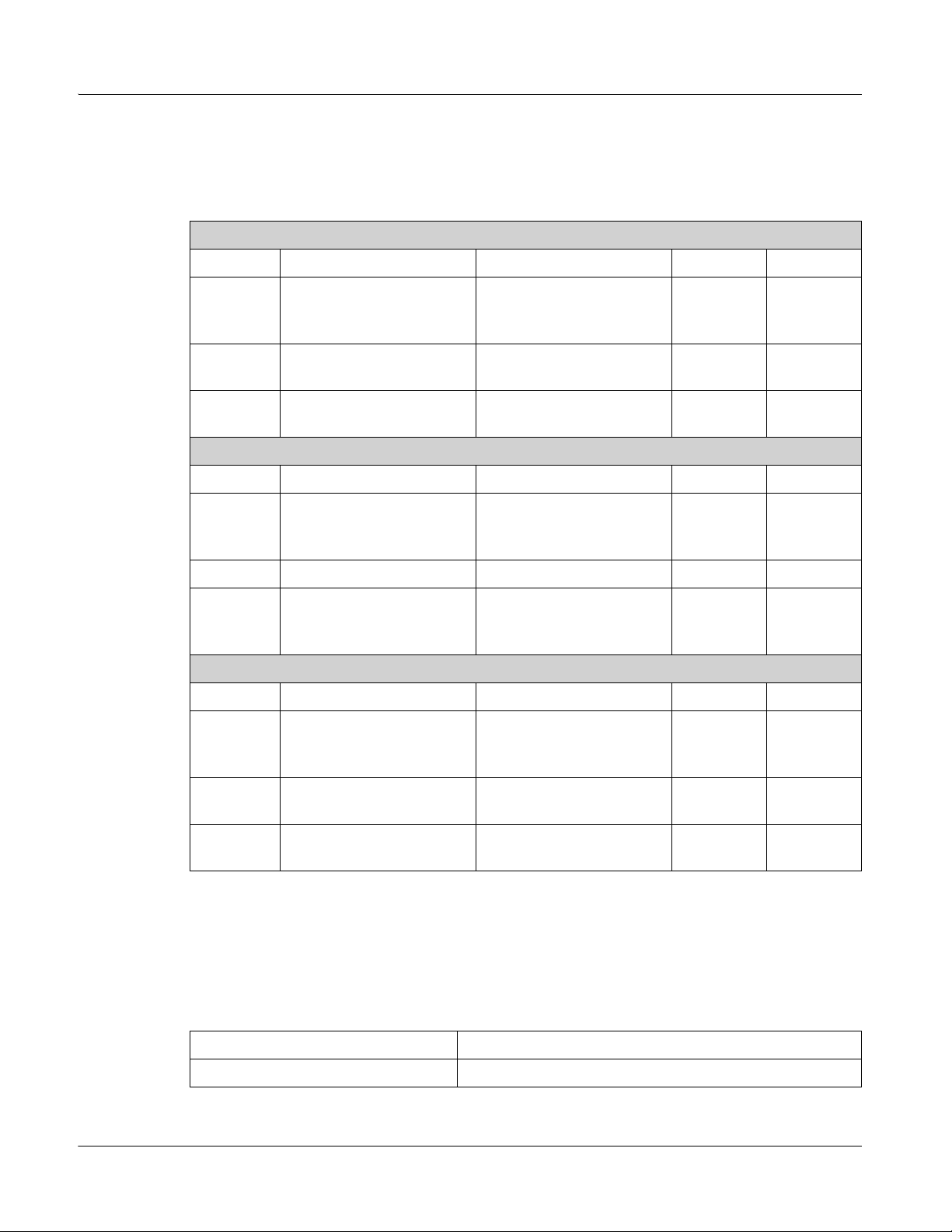
These LEDs are for each port. The meaning of the LEDs is defined in Table 4.
Table 4 12G SAS Blade LEDs
12G SAS Blade LEDs for Analyzer Ports
LED Green Orange/Yellow ON OFF
Link present (solid)
Signal
Traffic coming
(flashing)
Triggered
Rate
12G SAS Blade LEDs for Jammer Ports
LED Green Orange Blue OFF
N/A N/A Triggered Not
Rate Link speed is not
set to the highest rate
Link present (solid)
Signal
Traffic coming
(flashing)
Triggered
N/A N/A N/A N/A
Link speed is 6Gbps Link speed is 12Gbps Link
Rate
Error
Traffic coming
(flashing orange)
Link speed is set to the
highest rate (yellow)
Error
Traffic coming
(flashing)
N/A No traffic
triggered
N/A N/A
N/A No traffic
N/A
speed is
3Gbps
12G SAS Blade LEDs for Generator Ports
LED Green Orange ON OFF
Signal
Link present (solid)
Traffic coming
Error Traffic coming
(flashing)
N/A No Traffic
(flashing)
Triggered
Rate
N/A N/A Triggered Not
triggered
Link speed is not set to
the highest rate
Link speed is set to the
highest rate
N/A N/A
12G SAS System Specifications
Table 5 Physical Specifications
Height 3.46 in. / 8.79 cm.
Width 9.50 in. / 24.13 cm.
Page 8 Xgig1000 Hardware Guide March 2017

Table 5 Physical Specifications
Depth 15.25 in. / 38.74 cm.
Weight 12.0 lbs. / 5.44 kg
Mount 18.84 in. / 47.85 cm
Table 6 Power Specifications
Power Consumption 375 W
Fuse Protection 5 A 250 V
Input Voltage Range 100−240 VAC
Input Frequency 50/60 Hz
Inrush Current (Peak) 3.5 A @ 100 VAC
Chapter 1 Xgig1000 System Overview
Xgig1000 12G SAS Chassis
Table 7 Port Specifications
Console Port 9-pin serial port connects to PC
(cross over cable only)
Management Ports 10/100/1000 RJ-45
Cascade Ports RJ-45 connection to additional units
(straight-through cable only)
TTL Inputs MCX Connector for Trigger IN (thin coaxial cable
only), The trigger-in can handle 3.3V or 5.0V
inputs, active-high.
TTL Outputs MCX Connector for Trigger OUT (thin coaxial
cable only), The trigger-out pulse is approximately
200ns wide, active-high, LVTTL (3.3V).
USB A 2.0 Port Type A, version 2.0, Capable of up to 480 Mbps
USB A 3.0 Ports Type A version 3.0, Capable of up to 5 Gbps
USB B 3.0 Port Type B version 3.0, Capable of up to 5 Gbps
Clock In MCX Connector for Transmit Reference Clock
Input, 375 MHz, AC-coupled, Typ. 0.8V,
Max 1.2V peak-peak
Clock Out MCX Connector for Transmit Reference Clock
Output, 375 MHz, AC-coupled,
Typ. 0.8V peak-peak
Port Connectors mini-SAS HD ports connect to DUT(s)
March 2017 Xgig1000 Hardware Guide Page 9
Chapter 1 Xgig1000 System Overview
Xgig1000 12G SAS Chassis
Table 8 Environmental Spe cificat ions
Temperature
Operational
Non-operational
Humidity
Operational
Non-operational
Vibration
Operational
Non-operational
Electromagnetic Compliance FCC Class A, CE Compatibility
10 to +40° C (50 to +104° F)
−40 to +70° C (−40 to +158° F)
Up to 90% humidity (non-condensing) at +40° C
Up to 95% humidity at +65° C.
Random Vibration 5−500 Hz, 10 minutes per axis,
2.41g (rms)
Random vibration 5−500 Hz, 10 minutes per axis,
0.3 g (rms) Resonant search, 5−500 Hz swept
sine, 1 octave/min. sweep rate, 0.75 g,
5 minute resonant dwell at 4 resonances/axis
Safety UL
Page 10 Xgig1000 Hardware Guide March 2017

Xgig1000 4 Port 10G/16G Chassis
The Xgig1000 4 Port 10G/16G system is a fixed blade chassis that houses one Xgig 10G/
16G blade with four ports (two links). The Xgig1000 4 Port 10G/16G system supports the
Analyzer, Jammer, and Load Tester functions at 10.3125 Gbps in the 10 Gigabit Ethernet
protocol. Analyzer and Load Tester are supported in Analog Passthrough and Digital
Retime. Jammer is supported in Digital Retime only. This system also supports the
Analyzer, Jammer, and Load Tester functions at 4.2500, 8.5000, or 14.0250 Gbps in the
Fibre Channel protocol in Analog Passthrough or Digital Retime. This system supports a
4GB trace buffer per port. This fixed-blade system does not require or accept Xgig or
Xgig5000 blades. Xgig provides the necessary software tools running in a PC environment
to perform the application task using the blade fixed within the chassis.
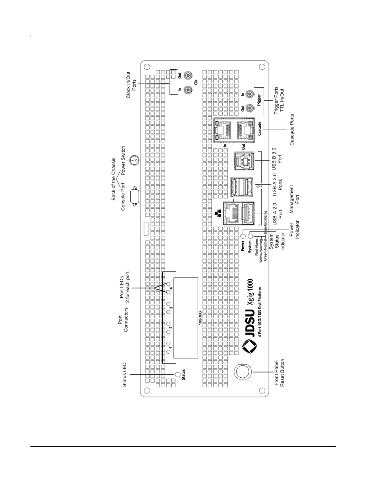
The Xgig1000 4 Port 10G/16G chassis is shown in Figure 2.
Chapter 1 Xgig1000 System Overview
Xgig1000 4 Port 10G/16G Chassis
March 2017 Xgig1000 Hardware Guide Page 11
Chapter 1 Xgig1000 System Overview
Xgig1000 4 Port 10G/16G Chassis
Figure 2 Xgig1000 4 Port 10G/16G Chassis
Page 12 Xgig1000 Hardware Guide March 2017

Chapter 1 Xgig1000 System Overview
Xgig1000 4 Port 10G/16G Chassis
4 Port 10G/16G System Ports/Connections/Front Panel Reset Button
Management Port
The Management port provides a connection to the 10/100/1000 network or a direct
connection to a PC's 10/100/1000 Ethernet adapter . The Management port is used for the
following:
• Configuring the Xgig1000 chassis using the Xgig Web Utility
• Controlling the operation of Xgig application-specific blades
• Retrieving data collected by Xgig application-specific blades
Console Port
The Console port is a 9-pin serial port on the back of the chassis. The Console port is used
for the following:
• Configuring the Xgig1000 chassis
• Selecting the Xgig1000 boot image (this functionality is not available through the
Console port for second generation chassis. Instead, these chassis use the USB
system recovery drive.)
• Minor troubleshooting
• Basic administration
The Console port can be used for all system configuration through a command line interface. Configuration commands are passed to Xgig by connecting the Console port to a
terminal or to a PC with a terminal emulation program using a cross-over cable. However ,
configuration is usually performed using the Xgig Web Utility over the internet throug h the
10/100/1000 Ethernet management port.
Trigger/TTL Ports
The TTL Input and TTL Output ports provide a means of sending or receiving an electrical
signal between the Xgig and other instruments for triggering purposes.
The trigger-out pulse is approximately 200ns wide, active-high, L VTTL (3. 3V). The triggerin can handle 3.3V or 5.0V inputs, also active-high. Use 50 ohm cables with these ports.
Cascade Ports
The Cascade In and Cascade Out ports provide a means of time-synchronizing up to four
Xgig, Xgig5000, and/or Xgig1000 chassis. Cascade Ports are used to share domains and
send triggers between chassis.
March 2017 Xgig1000 Hardware Guide Page 13
Chapter 1 Xgig1000 System Overview
Xgig1000 4 Port 10G/16G Chassis
Cascade ports use standard RJ-45 connectors and straight through CAT5 cables to
connect chassis, but use Viavi proprietary protocol to communicate between cascaded
units.
USB Ports
St andard USB type A conne ctor may be used with any USB 2.0 device. This includes the
USB system recovery drive for second generation Xgig1000 chassis.
3.0 USB type A connectors may be used with any USB 3.0 device.
3.0 USB type B connector may be used with an external host as a Manage ment port or for
USB administration.
NOTE
A USB driver is installed as part of the installation packa ge. If you choose to connect the
chassis using a USB extension cable, you may be prompted to re-install the USB driver.
Clock Ports
The Clock Out port provides a means of using the clock out signal to measure the eye
diagram of the output signal from the Analyzer. The Clock Out port accepts a SMA-type
cable.
The Clock In port functionality is TBD. This port is reserved for future use.
Port Connectors
The Xgig1000 has four female SFP connectors on the front.
Front Panel Reset Button
To safely shutdown the operating system and power off the chassis, press and hold the
Front Panel Reset button for two seconds until the System LED starts blinking yellow.
Stop pressing the button as soon as you see the System LED blink. This will allow the
system to do a graceful shutdown.
• For Xgig 1000 units with the original motherboard (no rear power switch on the
back panel), the System LED will become steady yellow when the system has shutdown. This is the indication that you can remove the power cable.
• For Xgig 1000 units with the new motherboard (rea r power switch on back panel),
all LEDs will go dark and the motherboard will show no power when the system has
completed the shutdown. At this point the power to both the protocol board and the
motherboard has been removed. The only power going into the chassis at that point
is into the Power Supply. This is the indication that you can switch the power switch
to the off position.
Page 14 Xgig1000 Hardware Guide March 2017
 Loading...