

Page 1
SmartClass
99 Washington Street
Melrose, MA 02176
hone 781-665-1400
P
Toll Free 1-800-517-8431
Visit us at www.TestEquipmentDepot.com
TM
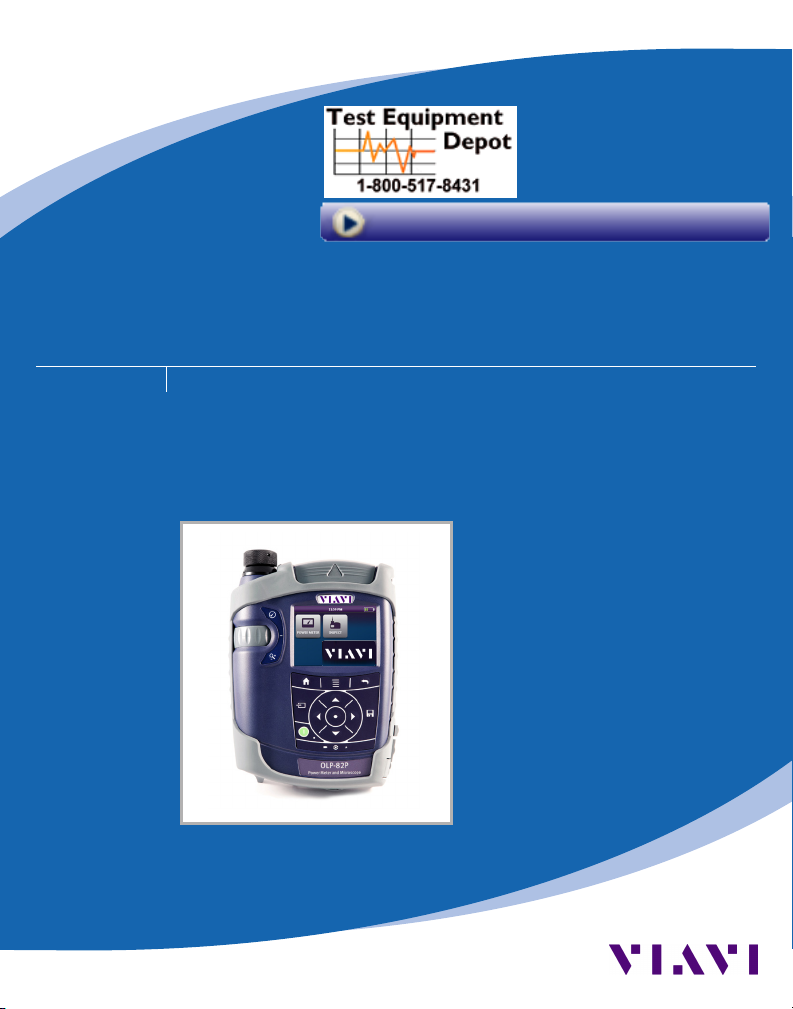
Fiber FBP-HD4i/HD4iP and OLP-82/82P
Inspect, test, certify, and save with one device
QUICK START GUIDE
22002195
REV 0 REV 0
Page 2

Notice Every eort was made to ensure that the information in this document was accurate at the time
of printing. However, information is subject to change without notice, and JDSU reserves the
right to provide an addendum to this document with information not available at the time that
this document was created.
Copyright © Copyright 2012 JDSU, LLC. All rights reserved. JDSU, Enabling Broadband and Optical
Trademarks JDSU is a trademark of JDSU in the United States and other countries.
FCC Information Electronic test equipment is exempt from Part 15 compliance (FCC) in the United States.
European Union Electronic test equipment is subject to the EMC Directive in the European Union. The EN61326
Independent
Laboratory Testing
Innovation, and its logo are trademarks of JDSU, LLC. All other trademarks and registered
trademarks are the property of their respective owners. No part of this guide may be reproduced
or transmitted electronically or otherwise without written permission of the publisher.
standard prescribes both emission and immunity requirements for laboratory, measurement,
and control equipment. This unit has been tested and found to comply with the limits for a
Class A digital device.
This unit has undergone extensive testing according to the European Union Directive and
Standards.
QUICK START GUIDE2
Page 3

TABLE OF CONTENTS
CHAPTER 1
CHAPTER 2
CHAPTER 3
INTRODUCTION ......................................................................................................................... 4–5
SmartClass Fiber Devices ..................................................................................................... 4
Key Features and Functions ................................................................................................ 5
CONTROLS .................................................................................................................................... 6–8
Operator Control Panel ........................................................................................................7
Home Screen Display ............................................................................................................ 8
OPERATION ................................................................................................................................ 9–11
Setting Up PASS/FAIL Analysis ........................................................................................... 9
Activate inspection with PASS/FAIL analysis......................................................9
Select acceptance criteria: Inspection (PCM) .................................................... 9
Select acceptance criteria: Inspection (Probe) ................................................10
Set up OPM PASS/FAIL thresholds (if measuring in dBm) ...........................10
Using the Device ...................................................................................................................11
SmartClass™ Fiber FBP-HD4i/HD4iP and OLP-82/82P 3
Page 4
CHAPTER 1 SmartClass™ Fiber FBP-HD4i/HD4iP and
OLP-82/82P
INTRODUCTION
1
Viavi’s SmartClass Fiber family is the next generation of optical handheld test solutions that allow
technicians to inspect, test, certify, and save on a single device. Designed to help users work smarter
and faster, the SmartClass Fiber family incorporates the features that technicians rely on every day to
deliver best-in-class reliable networks to their customers.
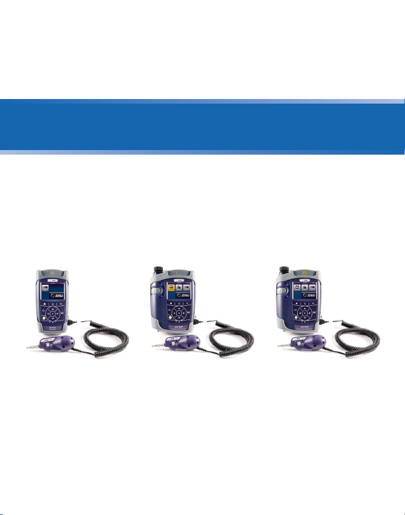
Products in the SmartClass Fiber family include:
HD4i
Digital handheld video
display
OLP-82
Digital handheld video
display with optical power
meter
QUICK START GUIDE4
OLP-87
Digital handheld video
display with PON power
meter
Page 5

Introduction CHAPTER 1
Key Features and Functions
Description HD4i OLP-82 OLP-87
Portable handheld display with 3.5" color touch screen
Simple graphical menu-driven interface
Accepts PASS/FAIL P5000i Probe
Accepts external USB power meter
Integrated connector certication reporting
On-board storage: Endface images and inspection analysis
User-denable acceptance criteria
Integrated optical power meter
On-board storage: Power meter results
Integrated PON power meter (BPON, EPON, and GPON)
Integrated PASS/FAIL patch cord microscope option
HD4iP OLP-82P OLP-87P
This Quick Start Guide highlights general controls and use the HD4i and OLP-82 products only.
A comprehensive User Manual is included on the FiberChekPRO installation disk that is included with this
product.
SmartClass™ Fiber FBP-HD4i/HD4iP and OLP-82/82P 5
Page 6

CHAPTER 2 SmartClass™ Fiber FBP-HD4i/HD4iP and OLP-82/82P
CONTROLS
Standard with Patch Cord Microscope (PCM)
2
u
v
w
x
y
z
{
|
}
~
QUICK START GUIDE6
Page 7

Controls CHAPTER 2
Connector interface
u
3.5 inch color touch screen
v
Key pad (operator control panel)
w
LED indicators
x
Patch Cord Microscope (PCM) with FMAE adapter
y
Test head cover
z
Battery life indicator
{
Graphic menu interface
|
2x USB2 interfaces, 1x micro-USB interface, external power supply connector
}
PCM controls (focus control, automated PASS/FAIL analysis, magnication control)
~
Operator Control Panel
HOME - Press to go to the home screen
MENU - Press to open a menu
BACK - Press to go back one step
INPUT SELECT KEY (ISK) - Press for fast toggling between device functions
POWER - Press to switch the instrument ON and OFF
NOTE: LED glows GREEN when the instrument is ON.
ARROW KEYS
• Press to navigate through the menus
• Press to change values in the menus
CENTER KEY
• Press to conrm the selection
SAVE - Press to save results
LOW BATTERY - Glows RED when battery is low
TEST IN PROCESS - Glows RED when a measurement is running in the background
CHARGE - Glows AMBER when battery is charging; If the power is OFF, charging will continue with no
LED indicator
SmartClass™ Fiber FBP-HD4i/HD4iP and OLP-82/82P 7
Page 8

CHAPTER 2 SmartClass™ Fiber FBP-HD4i/HD4iP and OLP-82/82P
Home Screen Display
OLP-82P Home Screen shown
Battery Status - Indicates the battery charge level / status.
Optical Power Meter (OPM) - Activates the on-board OPM to view optical power
measurement results, edit acceptance criteria, and view saved results.
Inspect (PCM) - Activates the integrated Patch Cord Microscope (PCM) to inspect
and analyze ber endfaces, detect scratches and defects, and provide PASS/FAIL
results. The PCM is ideal for inspecting male ber connectors such as patch cords
and test leads.
Inspect (Probe) - Activates the handheld P5000i Digital Probe microscope to
inspect and analyze ber endfaces, detect scratches and defects, and provide
PASS/FAIL results. The probe is ideal for inspecting connectors located behind
bulkheads.
USB Optical Power Meter (OPM) - Activates OPM devices (such as MP-60 or
MP-80) that are connected to one of the USB ports to view optical power
measurement results, edit acceptance criteria, and view saved results.
QUICK START GUIDE8
Page 9

Operation CHAPTER 3
OPERATION
3
Setting Up PASS/FAIL Analysis
Select Acceptance
Criteria:
Inspection (Probe)
Select Acceptance
Criteria:
Inspection (PCM)
1. Open the INSPECT (Probe) application
2. Press
MENU
3. Select PROFILE (choose desired PROFILE from list)
4. Select TIP (choose from list)
1. Open the INSPECT (PCM) application
2. Press
MENU
3. Select PROFILE (choose desired PROFILE from list)
SmartClass™ Fiber FBP-HD4i/HD4iP and OLP-82/82P 9
Page 10

CHAPTER 3 SmartClass™ Fiber FBP-HD4i/HD4iP and OLP-82/82P
Set Up OPM
PASS/FAIL
Thresholds
(if measuring in
dBm)
1. Open the POWER METER application
2. Select MORE... > EDIT WAVELENGTH TABLE
3. Select a wavelength from the list
4. Press
MENU
5. Select ENTER LIMIT
6. Enter you desired limit value (measured in dBm) using the numeric keypad
7. Press OK
• Repeat steps 4–7 for all desired OPM wavelengths
8. Check the boxes for only the wavelengths you want to use
QUICK START GUIDE10
Page 11

Operation CHAPTER 3
Using the Device
This SmartClass Fiber device allows users to inspect, test, certify, and save results
quickly and easily by driving the user’s behavior and incrementally stepping
them through each application as it should be used in a proper testing
workow as follows:
Starting from the Home Screen
1. Certify the patch cord/test lead endfaces
a. Press the
b. Inspect patch cord/test lead end A using the PCM
c. Press the [TEST] button on the PCM
d. Press to save result (if necessary)
e. Move end A over to the OPM port
f. Inspect patch cord/test lead end B using the PCM
g. Press the [TEST] button on the PCM
h. Press to save result (if necessary)
i. Leave end B in the PCM
to activate the PCM
2. Certify the bulkhead connector endface
a. Press the
b. Inspect the bulkhead endface using the Probe Microscope
c. Press the [TEST] button on the Probe
d. Press to save result
e. Plug patch cord/test lead end B into the bulkhead port
to activate the Probe Microscope
3. Measure the optical power
a. Press the
b. Select desired wavelength (OPM value will be displayed on the screen)
c. Press to save result
d. Repeat as necessary for other wavelengths
SmartClass™ Fiber FBP-HD4i/HD4iP and OLP-82/82P 11
to switch to the OPM
Page 12

99 Washington Street
Melrose, MA 02176
Phone 781-665-1400
Toll Free 1-800-517-8431
Visit us at www.TestEquipmentDepot.com
Test and Measurement Regional Sales
Product specications and descriptions in this document subject to change without notice. © 2012 JDS Uniphase Corporation. September 2012
22002195
REV 0
 Loading...