

Page 1
VIAVI Solutions
Quick Card
T-BERD®/MTS-5800 Network Tester
Ethernet Layer 3 Multicast Traffic Analysis
This document outlines how to use the T-BERD 5800 to join Layer 3 Multicast groups and receive and
analyze multicast traffic. Multicast traffic generation is covered in a separate Quick Card.
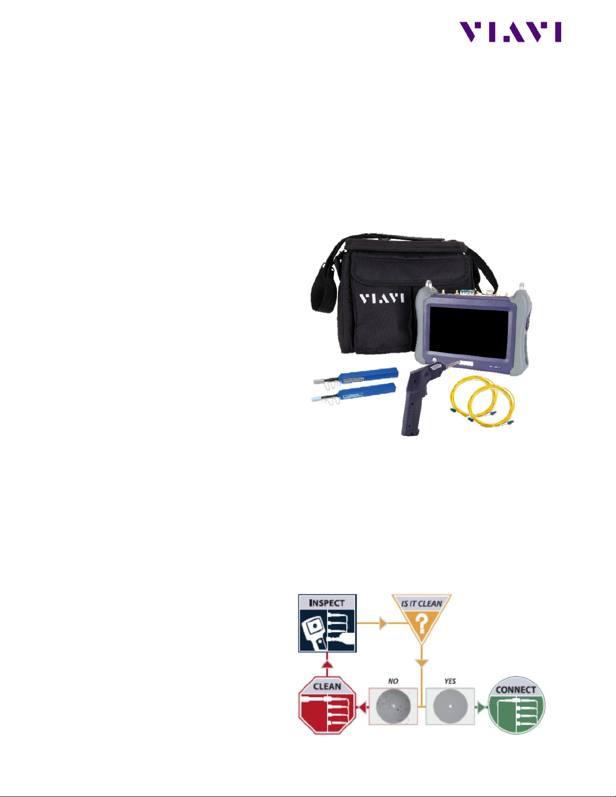
Equipment Requirements:
• T-BERD/MTS-5800 equipped with the
following:
o BERT software release V27.2 or
greater
o C510M1GE Gigabit Ethernet test
option
o SFP, QSFP, or CFP4 optical
transceiver to match the line under
test
• Patch Cables to match the T-BERD/MTS
optics and the line under test
• Fiber optic inspection microscope
(VIAVI P5000i or FiberChek Probe)
• Fiber Optic Cleaning supplies
Figure 1: Equipment Requirements
The following information is required to complete the test:
• Physical Interface (10/100/1000BASE-T, 1000BASE-LX, 10GBASE-LR, 100GBASE-LR4, etc.)
• Auto Negotiation settings of the port under test
• VLAN ID, if VLAN tagging is used
• IP Address Parameters (DHCP or Static, Source IP, Default Gateway, Subnet Mask)
• IP address for the Multicast Router that handles Multicast Group registration.
• One or more Multicast Group IP Address to receive multicast test traffic.
Fiber Inspection Guidelines:
• All fiber end-faces must be clean and
pass an inspection test prior to
connection.
• Use the VIAVI P5000i, FiberChek Probe,
or Sidewinder microscope to inspect
both sides of every connection being
used (SFP Port, bulkhead connectors,
patch cords, etc.)
Figure 2: Inspect Before You Connect
Page 2

VIAVI Solutions
Connect to Fiber Under Test (FUT):
1. For copper 10/100/1000BASE-T
interface testing with the T-BERD/MTS
5800v2, connect the Port 1
10/100/1000 RJ-45 jack to the port
under test using CAT 5E or better cable.
2. For copper 10/100/1000BASE-T
interface testing with the T-BERD/MTS
5800-100G, insert a copper SFP into the
Port 1 SFP+/SFP28 slot and connect to
the port under test using CAT 5E or
better cable.
Figure 3: T-BERD 5800v2 Dual Port mainframe
3. For optical interfaces:
• Insert SFP compatible with your
physical interface into the Port 1
slot on the top of T-BERD.
• Inspect and, if necessary, clean all
fibers and bulkheads, as described
on page 1.
• Connect the SFP to the port under
test using a Single Mode or
Multimode jumper cable compatible
with the interface under test.
Figure 4: T-BERD 5800-100G mainframe
Launch and Configure Test:
1. Press the Power button to turn on the test set and view the startup screen.
2. Using the Select Test menu, Quick Launch menu, or Job Manager, launch an Ethernet, Layer 3
Traffic, IPv4, Terminate test on port 1 for the desire physical interface. For example:
Ethernet►10/100/1000►Layer 3 Traffic►IPv4►P1 Terminate.
3. If the test is not in the default settings, tap the Tools icon and select .
Tap and wait for test to reconfigure.
4. Tap the Setup Soft Key to display the Interface settings tab.
5. If you are testing a 10/100/1000 Electrical or 1GigE Optical tests with auto negotiation disabled,
select the Physical Layer tab and configure settings to match the Ethernet port under test.
6. If the network under test uses VLAN tagging, select the Ethernet settings tab, set Encapsulation
to VLAN, tap [VLAN] and enter your VLAN ID.
Page 3

VIAVI Solutions
7. Select the IP settings tab.
8. Select the Source/Destination
Addresses field.
• Enter the Source IP, Default
Gateway and Subnet Mask values.
• Set Destination IP to the Multicast
Router IP address.
• The T-BERD/MTS will resolve the
destination IP address using the
Address Resolution Protocol (ARP).
Once resolved, the button
becomes available and you can use it
to verify connectivity to the
Multicast Router.
9. Select the IGMP settings tab.
10. Set IGMP Mode to Enabled.
11. Tap the Address Book button to
configure the Multicast Group
Membership.
Figure 5: IP Settings
Figure 6: IGMP Settings
12. Under the New Entry, enter the source
IP address of the T-BERD/MTS Source IP
address in the Source IP field and enter
the Multicast Group IP address in the
Dest. IP field. Optionally, enter a name
for the new entry.
13. Tap on the Add Entry button to save
the Multicast Group entry.
14. If more Multicast Groups need to be
joined during the test, repeat Steps 12
and 13 for all additional Multicast
Groups.
15. Tap on Save and Close button to save
the Address Book information.
16. Tap on the Results button in the upper
left screen corner to move to the
Results screen.
Figure 7: Address Book
Page 4

VIAVI Solutions
Contact Us +1 844 GO VIAVI)
(+1 844 468 4284)
To reach the VIAVI office nearest you,
visit viavisolutions.com/contacts.
© 2019 VIAVI Solutions Inc.
Product specifications and descriptions in this
document are subject to change without notice.
Join Multicast Groups:
1. If using the optical test port on
T-BERD/MTS press the Laser Off button
at the bottom of the screen to turn on
the laser. The button will turn yellow
and be relabeled Laser On.
2. Check LEDs: A green Signal Present LED
● indicates the T-BERD/MTS is receiving
an optical signal from the port under
test. Green Sync Acquired and Link
Active LEDs indicate that the TBERD/MTS has successfully connected
to the port under test and the link is
active.
3. Use one of the two Results boxes in the
middle of the screen to display the
Ethernet/L3 Link Counts results view to
analyze received multicast traffic.
4. Tap on the Join Streams… button in the
Actions tab at the bottom of the screen
to join the Multicast Groups.
5. Select one or more Multicast Group
entries under Address Book and tap the
Add button to add the entry to the To
Join list.
6. Tap the Join Steams button to join the
selected stream(s).
Figure 8: Results
Figure 9: Join Steams...
Analyze Multicast Traffic:
1. Once one or more Multicast Groups are
successfully joined, the T-BERD/MTS
will start receiving multicast test traffic
as indicated by the Multicast Packets
counter on the Ethernet -> L3 Link
Counts results view.
2. You can now use other available results
views to analyze the multicast traffic
performance.
Figure 10: Results view
 Loading...