

Page 1

Seeker HL
In-Home Leakage Detector
User’s Guide
Page 2

Notice
Every effort was made to ensure that the information in this manual was accurate at the time
of printing. However, information is subject to change without notice, and VIAVI reserves the
right to provide an addendum to this manual with information not available at the time that this
manual was created.
Copyright/Trademarks
© Copyright 2019 VIAVI Solutions Inc. All rights reserved. No part of this guide may be
reproduced or transmitted, electronically or otherwise, without written permission of the
publisher. VIAVI Solutions and the VIAVI logo are trademarks of VIAVI Solutions Inc. (“Viavi”).
All other trademarks and registered trademarks are the property of their respective owners.
Copyright release
Reproduction and distribution of this guide is authorized for US Government purposes only.
Ordering information
This guide is a product of VIAVI Technical Publications Department, issued as part of the
product. The catalog number for a published guide is Catalog Number - printed. The catalog
number for an electronic guide on USB is Catalog Number - electronic.
Terms and conditions
Specications, terms, and conditions are subject to change without notice. The provision
of hardware, services, and/or software are subject to VIAVI standard terms and conditions,
available at www.viavisolutions.com/en/terms-and-conditions.
Seeker HL User’s Guide
22130948, Rev. 003 March 2019Page 2
Page 3

Table of Contents
Chapter 1 .............................................................................................................. 5
General Information ..................................................................................................................5
Ordering Information ..............................................................................................................5
Where to Get Technical Support ............................................................................................5
How this Manual is Organized ...............................................................................................6
Optional Software...................................................................................................................6
Conventions Used in this Manual...........................................................................................7
Precautions ............................................................................................................................7
Chapter 2 .............................................................................................................. 9
Introduction ................................................................................................................................9
What is the Seeker HL? .........................................................................................................9
Overview ...........................................................................................................................9
Testing with the Seeker HL Source Transmitter ................................................................ 9
Seeker HL Features .............................................................................................................10
Easy Conguration .........................................................................................................10
Squelch Operation .......................................................................................................... 11
Source Localization ........................................................................................................11
Chapter 3 ............................................................................................................ 13
Getting to Know Your Seeker HL ...........................................................................................13
Overview ..............................................................................................................................13
Equipment Supplied with the Seeker HL ..............................................................................13
Replacement Parts...............................................................................................................13
Field Accessories .................................................................................................................14
A Guided Tour of Your Seeker HL ........................................................................................ 15
Front View .......................................................................................................................15
Right Side View ..............................................................................................................16
Protective Carrying Case ................................................................................................17
Display Screen................................................................................................................18
About the Battery of Your Seeker HL ...................................................................................20
USB Charging .................................................................................................................20
Seeker HL User’s Guide
22130948, Rev. 003March 2019 Page 3
Page 4

Chapter 4 ............................................................................................................ 21
Seeker HL Operation ...............................................................................................................21
Available Conguration Settings ..........................................................................................21
Basic Operation....................................................................................................................22
Power On/Off ..................................................................................................................22
Low Battery Warning ......................................................................................................22
PC Communications Mode .............................................................................................22
RF Signal Measurement Mode .......................................................................................23
Device Information & Settings ..............................................................................................26
Viewing the Battery Charge Level ..................................................................................26
Low Battery Alert .......................................................................................................27
Firmware Version ......................................................................................................27
Ambient Noise Level Measurement ................................................................................28
Speaker Volume Level .........................................................................................................30
Adjusting the Speaker Volume........................................................................................30
Chapter 5 ............................................................................................................ 31
Leakage Testing .......................................................................................................................31
Before You Begin Leakage Testing ......................................................................................31
Testing For Leaks ................................................................................................................. 31
Chapter 6 ............................................................................................................ 33
Appendix ..................................................................................................................................33
Specications .......................................................................................................................33
Display Messages & Error Codes ........................................................................................34
Seeker HL Error Codes ..................................................................................................34
Limited Warranty ..................................................................................................................35
Seeker HL User’s Guide
22130948, Rev. 003 March 2019Page 4
Page 5

Chapter 1
General Information
Ordering Information
For additional information about our products and services, contact your local Viavi
representative or visit https://www.viavisolutions.com/en-us/how-buy.
Where to Get Technical Support
Phone US: +1-844-GO-VIAVI or +1-844-468-4284
Outside US: +1-855-275-5378
Email: Trilithic.support@viavisolutions.com
Website: https://support.viavisolutions.com/welcome
Seeker HL User’s Guide
22130948, Rev. 003March 2019 Page 5
Page 6

How this Manual is Organized
This manual is divided into the following chapters:
• Chapter 1, “General Information” provides contact information and describes how this
operation manual is structured.
• Chapter 2, “Seeker HL Introduction” introduces what the Seeker HL is and what it does.
This chapter discusses the practical application, connections and controls of the Seeker
HL. Finally, this chapter discusses the battery of the Seeker HL and how to update your
rmware.
• Chapter 3, “Seeker HL Operation” describes how to congure and operate the Seeker
HL.
• Chapter 4, “Leakage Testing” describes the steps needed to perform leakage testing
using the Seeker HL.
• Chapter 5, “Appendix” shows the technical specications of the Seeker HL as well as
any error codes that may appear on the display screen of the Seeker HL.
Optional Software
Although the Seeker HL comes precongured and ready to use from the factory, the following
software is required for advanced conguration of the Seeker HL:
• Seeker Setup is used to congure the Seeker HL, enabling the operator to assemble
les containing channel frequencies, squelch levels, and other settings. Users can
efciently download congurations to one or more leakage detectors.
• Leakage Analysis Workshop (LAW) is software that manages the storage and
retrieval of leakage information collected by vehicle mounted Seeker GPS systems.
Installed on a server, it receives leakage data uploads via the Internet/LAN, Wi-Fi
access point, or cellular connection. Data stored in LAW server may be displayed on
maps or as text, used to generate leakage work orders, or downloaded to other VIAVI or
third-party applications.
Data acquired by the Seeker HL must be manually entered into LAW, as the Seeker HL
does not communicate directly to LAW.
Seeker HL User’s Guide
22130948, Rev. 003 March 2019Page 6
Page 7
Conventions Used in this Manual
This manual has several standardized conventions for presenting information:
• Connections, menus, menu options, and user-entered text and commands appear in
bold.
• Section names, web, and e-mail addresses appear in italics.
A NOTE is information that will be of assistance to you related
to the current step or procedure.
A CAUTION alerts you to any condition that could cause a
mechanical failure or potential loss of data.
A WARNING alerts you to any condition that could cause
personal injury.
Precautions
Do not use the Seeker HL in any manner not recommended
by the manufacturer.
A strong electromagnetic eld may affect the measurement
accuracy of the Seeker HL.
Use only the battery charger supplied with the Seeker HL.
All spent batteries should be disposed of according to local
laws and guidelines.
Seeker HL User’s Guide
22130948, Rev. 003March 2019 Page 7
Page 8

Seeker HL User’s Guide
22130948, Rev. 003 March 2019Page 8
Page 9
Introduction
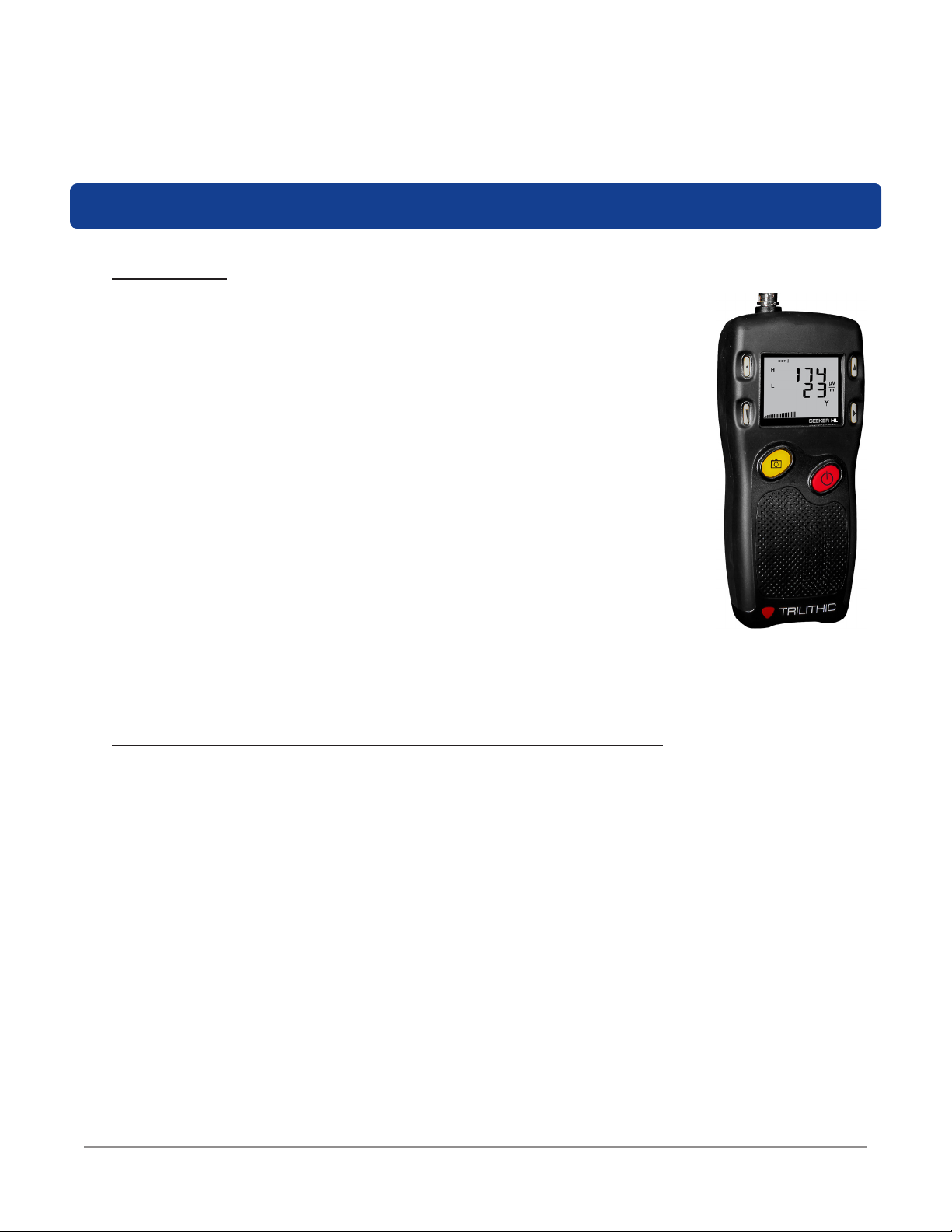
What is the Seeker HL?
Overview
Mitigation of signal leakage within the subscriber premise is essential for
the successful operation of the subscriber’s cable and cellular services. To
thoroughly evaluate the potential for interference to subscriber services,
VIAVI has developed a patent pending approach to signal leakage
measurement which will comprehensively test the Aeronautical and LTE
bands in both fully digital and analog cable systems.
Historically, signal leakage detectors have required high levels of sensitivity
to measure signal leakage radiating from the CATV system. Measurement
within the subscriber premise and the migration to all digital services places
even greater sensitivity requirements upon the leakage detector combined
with a new requirement to simultaneously monitor for signal leakage in both
the aeronautical and LTE bands.
Chapter 2
In laboratory experiments signal leakage measurements as low as
0.1 uV/m have proven sufcient to allow LTE signals to enter the subscriber
network and disrupt cable services. Achieving a measurement sensitivity
of 0.1 uV/m is beyond the measurement range of conventional signal leakage detectors and
requires a new approach to leakage detection within the subscriber premise.
Testing with the Seeker HL Source Transmitter
To meet the new measurement and sensitivity requirements, the Seeker HL monitors 138
MHz and 757.5 MHz simultaneously, supporting testing in both the Aeronautical and LTE
frequency bands. The Seeker HL Source Transmitter replaces the cable service with two
high-output test carriers which pressurize the subscriber cabling, revealing any damage
which may lead to service interruption from ingressing LTE carriers.
The Seeker HL Source Transmitter has two output levels: a +60 dBmV for home
certication and a +40 dBmV output level should the subscriber network prove too porous
for pinpointing the location of a leak at the higher transmit level.
The displayed leakage levels are normalized by the Seeker HL receiver to reect the value
of the leak at nominal systems levels within the subscriber premise. The normalization
of the measured and displayed leakage levels simplies the evaluation of leakage
severity and provides consistency for documentation of leakage levels in accordance with
established industry practices.
Seeker HL User’s Guide
22130948, Rev. 003March 2019 Page 9
Page 10
When utilizing the higher +60 dBmV transmit level the Seeker HL is able to locate signal
leakage down to a normalized leakage level of 0.1 uV/m with a single exible antenna;
making it possible to locate and repair signal leakage levels far beyond the measurement
range of conventional leakage detectors.
Seeker HL Features
Easy Configuration
The Seeker Setup software simplies the conguration process. Instead of going to the
factory to make hardware modications, you can use the Seeker Setup software to adjust
settings.
For the sake of this manual, the term “low frequency” refers
to 138 MHz and “high frequency” refers to 757.5 MHz.
Seeker HL User’s Guide
22130948, Rev. 003 March 2019Page 10
Page 11
Squelch Operation
Squelch level is the RF signal threshold that the Seeker HL uses to determine the validity
of the signal. The signal “breaks squelch” when the RF leakage is greater than the squelch
level and tag qualiers are met as well. The receiver will not alarm for signals below the
squelch level.
The squelch level has a factory default of 5 µV/m. However, it can be recongured using
the Seeker Setup software.
Source Localization
The Seeker HL emits an audible tone to help you pinpoint the leakage source. The tone
frequency increases proportional to signal strength. As you move closer to the leak, the
frequency of the tone will increase.
Common leakage areas are around the tap, drop cable,
ground block, CPE, and any connection of the cable to other
devices.
Seeker HL User’s Guide
22130948, Rev. 003March 2019 Page 11
Page 12

Seeker HL User’s Guide
22130948, Rev. 003 March 2019Page 12
Page 13

Chapter 3
Getting to Know Your Seeker HL
Overview
Before using your instrument take a few minutes to familiarize yourself with the instrument,
its basic conventions and its navigational tools. This section provides a brief overview of the
instrument’s features, buttons, and controls.
Equipment Supplied with the Seeker HL
The Seeker HL comes with the following:
• Seeker HL Leakage Detector
• Dual-Band Frequency Matched Rubber Duck Antenna
• Near Field Probe (NFP-1)
• AC to DC Power Adapter & Battery Charger
• USB Charge & Data Cable (Mini-B to Standard-A Male)
• Protective Carrying Case
• Shoulder Strap
Replacement Parts
The following replacement parts are available for the Seeker HL:
Part Number Description
0610169006
0610169002
2071585004 USB Charge & Data Cable
2131597000 Seeker HL Protective Carrying Case
0090048000 Seeker HL Battery
AC to DC Power Adapter & Battery Charger with USB Charge/Data
Cable
AC to DC Power Adapter & Battery Charger without USB Charge/
Data Cable
2072350001 Dual-Band Frequency Matched Rubber Duck Antenna
2010477000 Near Field Probe (NFP-1)
To place an order, contact your local VIAVI representative, call 1-844-GO-VIAVI, or visit
https://www.viavisolutions.com/en-us/how-buy.
Seeker HL User’s Guide
22130948, Rev. 003March 2019 Page 13
Page 14

Field Accessories
The following accessories are available for the Seeker HL:
Part Number Description
0610169007 Vehicle Power Adapter with USB Cable (CL-9)
0610169004 Vehicle Power Adapter without USB Cable (CL-9)
2071585004 USB Charge & Data Cable
0610169012 Euro Power Adapter
0610169013 UK Power Adapter
0610169014 Australian Power Adapter
To place an order, contact your local VIAVI representative, call 1-844-GO-VIAVI, or visit
https://www.viavisolutions.com/en-us/how-buy.
Seeker HL User’s Guide
22130948, Rev. 003 March 2019Page 14
Page 15

A Guided Tour of Your Seeker HL
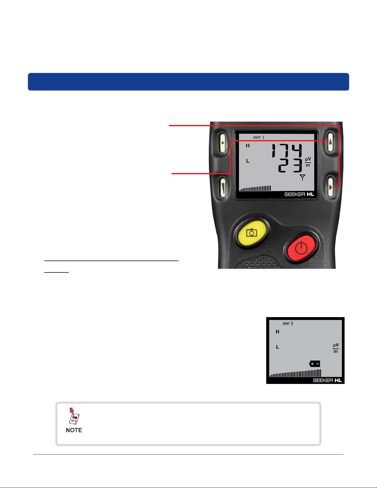
Front View
DISTANCE button
Press this button to change the distance from
value from 1 to 9 meters. 3 meters is normal
operation; 1 meter is near-eld mode.
VOLUME button
Press this button to change the speaker volume
of the leakage tone. Brief presses increase the
volume to maximum and then it rolls over to the
minimum volume.
SNAPSHOT button
This button stores the current leakage value.
ON/OFF button
Press and hold this button to turn the Seeker
HL on or off. Also, when the meter is on,
briey press this button to activate the display’s
backlight for approximately 60 seconds.
CHANGE button
Toggles or alters the current display selection.
SELECT button
Press to advance to the next display mode.
Seeker HL User’s Guide
22130948, Rev. 003March 2019 Page 15
Page 16

Right Side View
Mini-USB connection
The Mini-USB connection is used to connect the charger
to the Seeker HL and/or to connect a PC or laptop
computer to the Seeker HL using the mini-USB charge /
data cable.
Seeker HL User’s Guide
22130948, Rev. 003 March 2019Page 16
Page 17
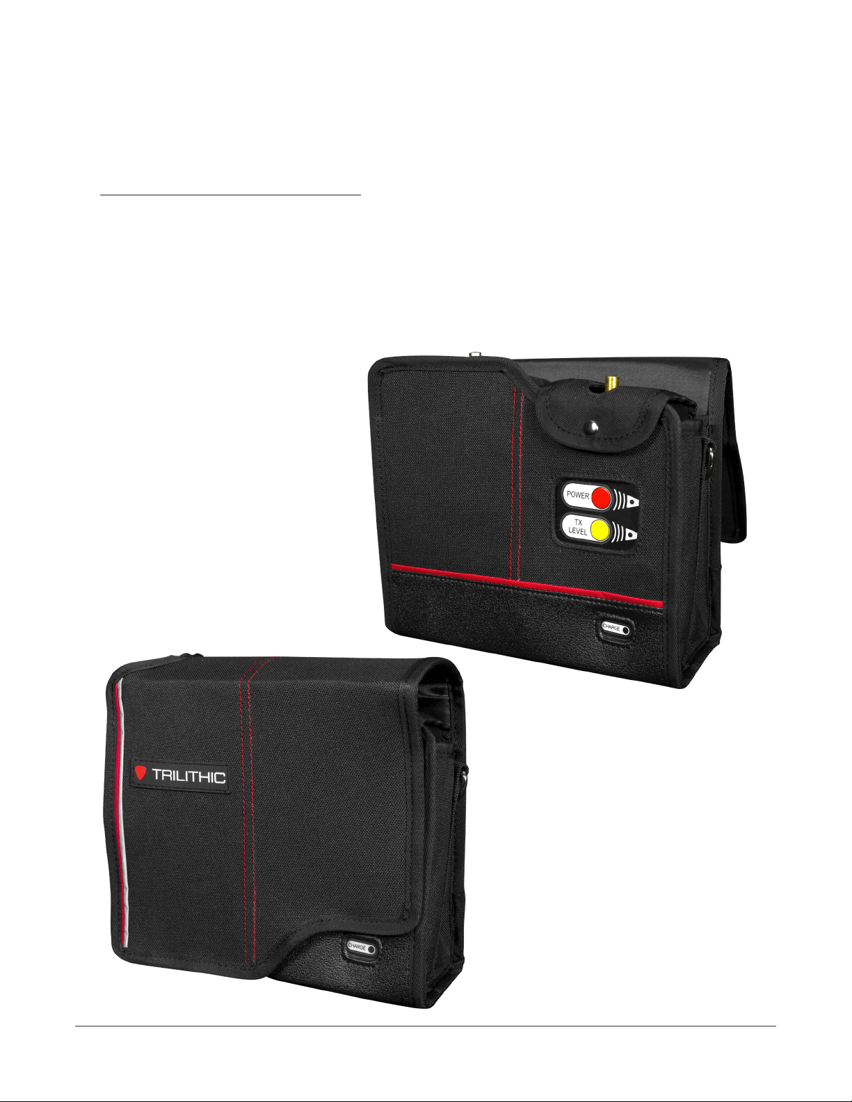
Protective Carrying Case
The Seeker HL includes a protective carrying case with the following features:
• Enough area to carry the Seeker HL, Seeker HL Source Transmitter, rubber duck
antenna, and near eld probe
• Removable shoulder strap (not shown)
• Metal D-rings for shoulder strap or line hook with reinforced stitching throughout
Seeker HL User’s Guide
22130948, Rev. 003March 2019 Page 17
Page 18
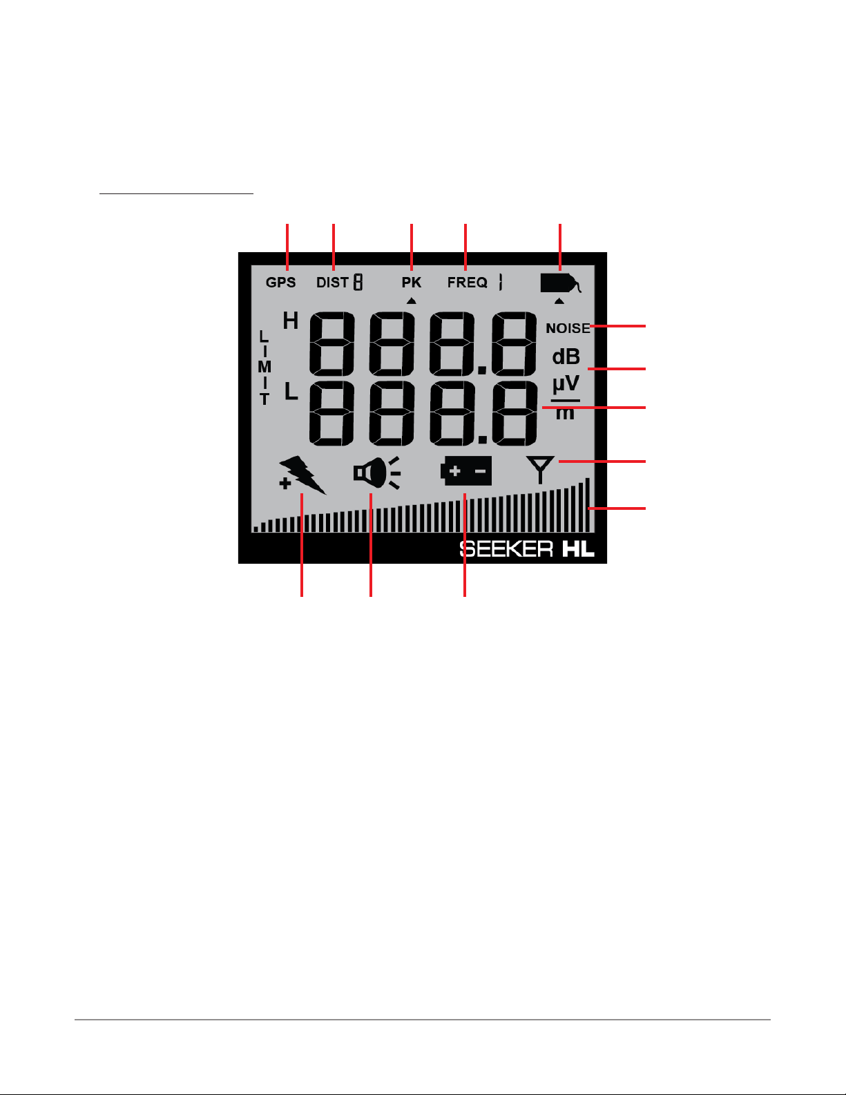
Display Screen
1 2 3 4 5
6
7
8
9
10
111213
1. GPS – Not used on this meter.
2. DIST – Indicates the distance from 1 to 9 meters. 3 meters is normal operation; 1 meter
is near-eld mode.
3. PK – Not used on this meter.
4. FREQ – Not used on this meter.
5. Tag – Shown when tagged signal leakage is detected.
6. NOISE – Not used on this meter.
7. Measurement units – Indicates leakage measurement units as selected in Seeker
Setup.
8. Main display – Shows various parameters, and its function depends on the current
display mode selection.
9. Antenna – Flashes when the signal mode is selected. This is the normal mode for
leakage detection.
Seeker HL User’s Guide
22130948, Rev. 003 March 2019Page 18
Page 19

10. Bar graph – Shows the level of various Seeker HL parameters, and its function
depends on the current display mode selection.
11. Battery – Flashes when the battery mode is selected. The icon will stay on when the
battery needs to be recharged.
12. Speaker – Flashes when the Speaker Volume Level mode is selected.
13. Charge – Flashes when the battery is being charged, or when the Battery Charge Level
screen is displayed.
If you see any of the following messages on your display:
• The word “Err” along with a number – Please call VIAVI Technical Support at
+1-844-GO-VIAVI.
• PC – Appears when the Seeker HL is connected to a PC and is in PC Communications
mode.
• CH – Appears when the Seeker HL is connected to a battery charger and is in Charge
mode.
• LO – Appears when the Seeker HL battery is too low for the meter to function.
Seeker HL User’s Guide
22130948, Rev. 003March 2019 Page 19
Page 20

About the Battery of Your Seeker HL
The Seeker HL uses a Lithium-Ion battery. The battery is charged during manufacture and
should be ready to use as long as it has not been stored for a long period of time.
Lithium-Ion batteries operate differently than Nickel-Cadmium batteries. They should be
charged daily, and should not be deeply discharged, as this could damage the battery. There is
no memory effect, so there is no concern for frequent charging.
USB Charging
You can charge the Seeker HL using either of the following USB charging methods:
• Connecting the Mini-USB cable and charger from an AC power source to the Seeker
HL. The Mini-USB charge / data cable and charger must be connected to both the
Seeker HL and a working power outlet before AC charging can begin.
• Connecting the Mini-USB charge / data cable from a PC or laptop computer to the
Seeker HL. The Mini-USB charge / data cable must be connected to both the Seeker
HL and a PC or laptop computer that is ON before USB charging can begin.
The following conditions apply when charging the Seeker HL via USB:
• When the Seeker HL is off and it is charging, the device will go into background
charging and nothing will be shown on the display screen.
• If the Seeker HL is on when it is connected to a to a PC, laptop computer, or working
power outlet, the device will automatically turn off.
• If the Seeker HL is turned back on when USB charging, the Measurement mode is
disabled while the Seeker HL is USB charging.
• When the Seeker HL is on and is charging, the screen shown in the image to the
right will be displayed, the Charge icon will ash, and the on-screen bar graph will
show the charging progress.
Seeker HL User’s Guide
22130948, Rev. 003 March 2019Page 20
Page 21
Chapter 4
Seeker HL Operation
Available Configuration Settings
You must congure the settings of the Seeker HL using the Seeker Setup software. The
Seeker HL comes from the factory with default settings, but they may need to be customized
for your application. Detailed instructions can be found in the Seeker Setup Software Operation
Manual.
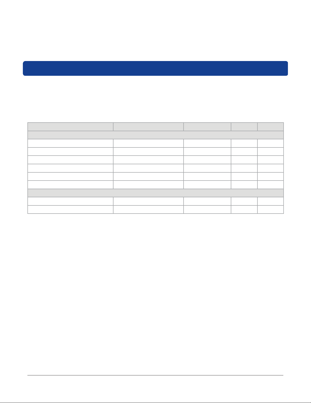
Feature Available Values Default Value Device Software
Display & Notification Settings
Set Display Units uV/m, dBuV, dBuV/m uV/m NO YES
Squelch 0.1 to 1000 uV/m 5 uV/m NO YES
Enable Meter Entry Disabled or Enabled Disabled NO YES
Input Level 60 or 40 dBmV 40 dBmV YES YES
Offset (dB) 20 to 80 dB 20 dB YES YES
Limit uV/m 0.1 to 1000 uV/m 0.1 NO YES
Device Management
Technician ID Custom Alphanumeric trilithi NO YES
Update Firmware N/A N/A NO YES
Seeker HL User’s Guide
22130948, Rev. 003March 2019 Page 21
Page 22

Basic Operation
Power On/Off
Press and hold the red ON/OFF button until you hear three ascending tones. Within a few
moments your Seeker HL will startup into the RF Signal Measurement Mode.
Low Battery Warning
A very low battery may cause the Seeker HL not to turn on. When
the battery is too low for your Seeker HL to function, the screen
shown to the right will appear. The battery must be charged for a
few minutes before using again.
Low Battery Warning
PC Communications Mode
This mode is used by the Seeker Setup software to send and
retrieve conguration parameters from your Seeker HL. To enter
this mode, connect the Seeker HL to a PC or laptop computer
using a mini-USB charge / data cable and then open the Seeker
Setup software to communicate with the Seeker HL. The screen
shown to the right will be displayed while your Seeker HL is in this
mode.
PC Communication Mode
Seeker HL User’s Guide
22130948, Rev. 003 March 2019Page 22
Page 23

RF Signal Measurement Mode
The RF Signal Measurement Mode is the default display mode for leakage testing and is
used to accurately determine the strength of a leak, pinpoint its location, and provide a
leakage value for documentation. Measured RF leakage values can range from 0.1 to 1000
µV/m and are displayed in large, easy-to-read numbers. A bar graph at the bottom of the
display illuminates proportionally to the signal strength of the leak.
Additionally, an audible tone will sound if the measured signal breaks squelch. The signal
breaks squelch when the RF leakage is greater than the squelch level and tag qualiers are
also met. This tone can be used to help locate the source of the leak and, perhaps more
importantly, the potential source of ingress.
The image displayed to the right represents the leakage detector
measurement mode with no signal detected. Notice how no
values are displayed and the bar graph at the bottom of the
screen remains blank.
Within the leakage detector measurement mode, the antenna
icon in the lower right side of the screen ashes to indicate that
the leakage detector is currently taking measurements.
No Signal Detected
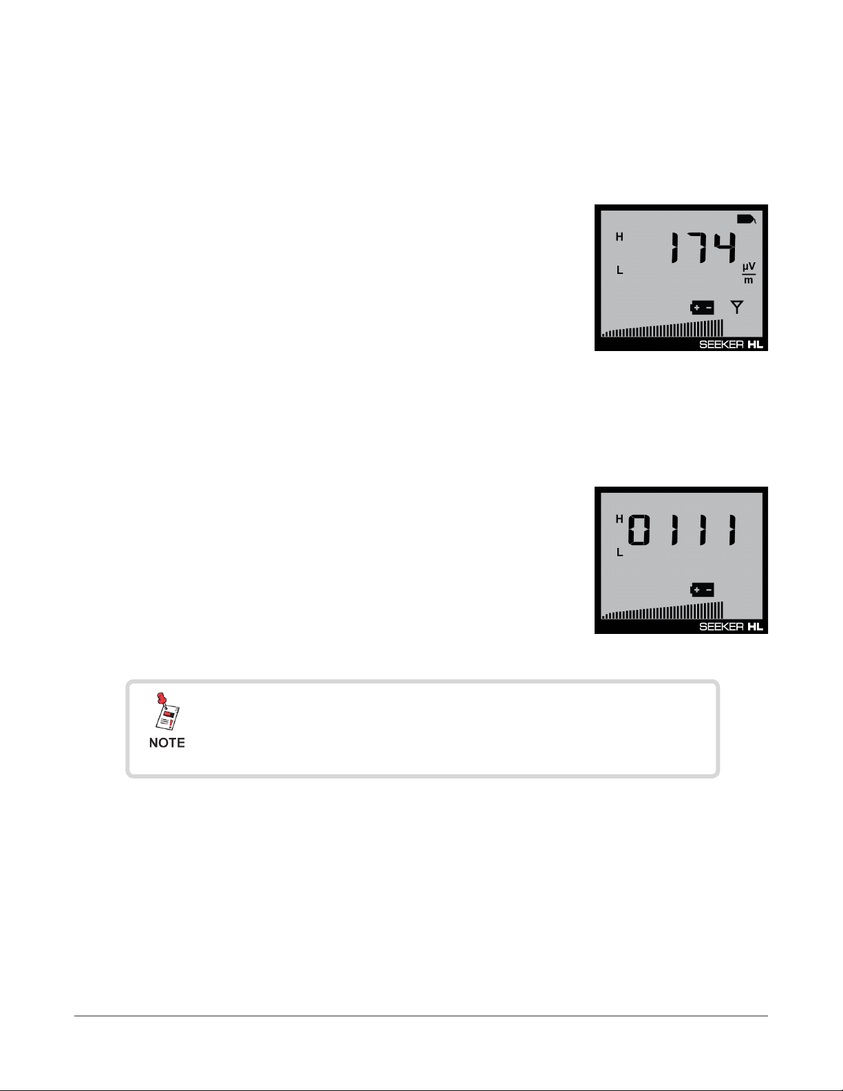
The image displayed to the right indicates detected leakage
values of 174 uV/m at 757.5 MHz and 23 uV/m at 138 MHz. The
bar graph at the bottom of the screen will display the relative
signal level of the detected signal.
Additionally, when the show noise setting is turned off, the tag
icon will be displayed in the upper right corner of the display to
indicated that the leakage detector is receiving the tagged signal
from the Seeker HL Source Transmitter.
If the tag icon is not displayed along with the signal level, the
show noise setting is turned on. In this mode, the signal levels
that are displayed will also include non-tagged noise that is
received by the leakage detector.
Tagged Signal Detected
(High Frequency)
Untagged Signal Detected
Seeker HL User’s Guide
22130948, Rev. 003March 2019 Page 23
Page 24

Distance Settings
The image displayed to the right represents the leakage detector set
to near-eld measurement mode, as indicated by “DIST 1”.
The Distance button (upper left) is used to select the desired
distance. “DIST 1” through “DIST 9” equates to 1 meter to 9 meters
respectively.
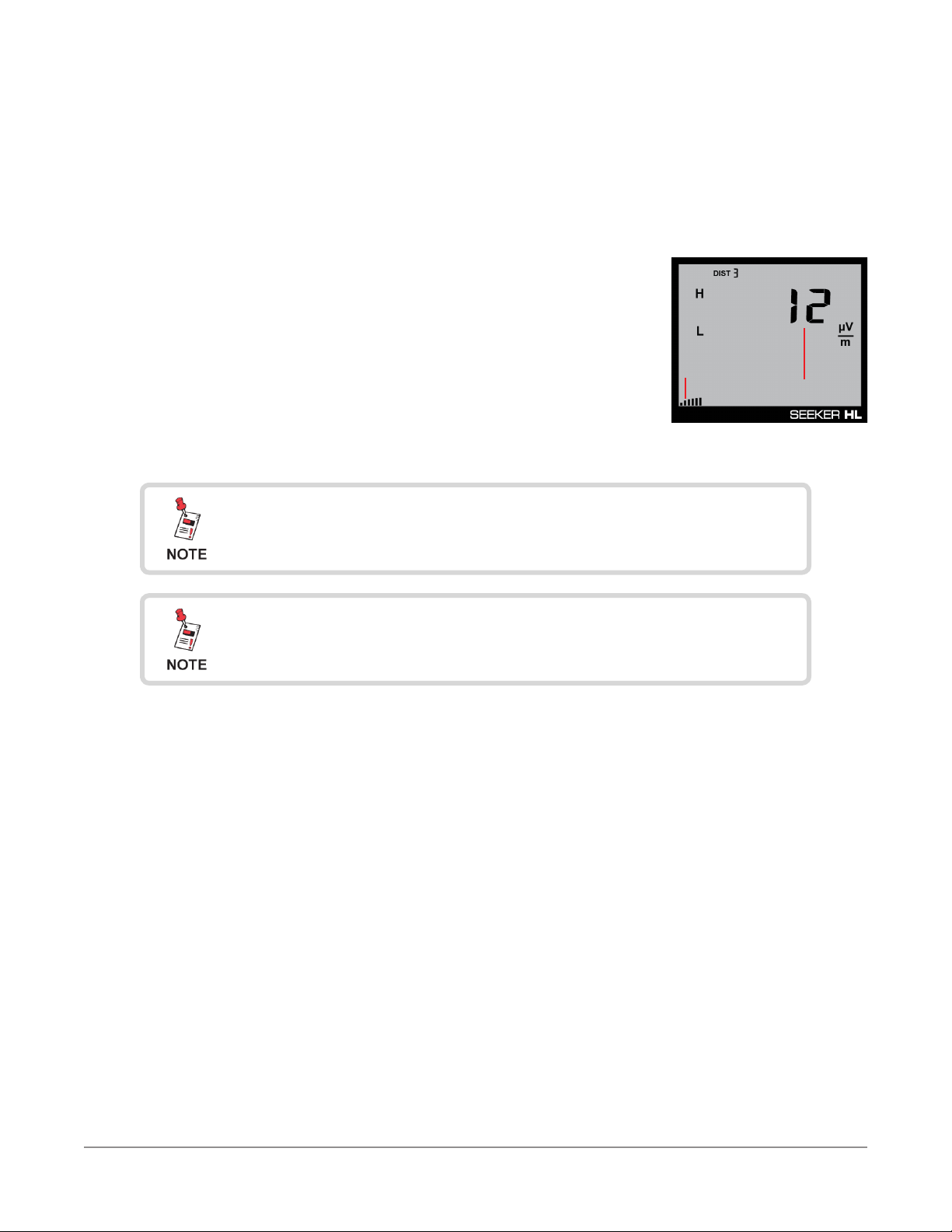
The image displayed to the right represents the normal measurement
mode of the leakage detector set to 3 meters, as indicated by “DIST
3”.
Seeker HL User’s Guide
22130948, Rev. 003 March 2019Page 24
Page 25

Offset Level Settings
The image displayed to the right shows the offset levels for both the
high and low frequencies. These values are used to normalize the
leakage readings to typical system levels.
Example: If the transmitter is injecting 60 dBmV at the ground block
and typical system level is 0 dBmV, with a 60 dB offset, the leakage
readings will reect what the leakage values would be as if the launch
level at the house were 0 dBmV.
If the “Enable Meter Entry” checkbox is checked within the Seeker
Setup software during conguration, these levels are adjustable on the leakage detector.
We recommend to uncheck this setting so that these values are not visible on the leakage
detector and can only be adjusted in Seeker Setup.
Press the SELECT button (middle right) once to view the offset level settings. The rst digit
of the high-frequency offset levels will begin to ash. To adjust the value of the selected digit
upward, press the CHANGE button (upper right).
Press the SELECT button (middle right) again to move the selection to the next digit and
continue this process until you are nished entering the offset values. The offset value for both
the high and low frequencies can be set anywhere from 20 to 80 dB.
Input Level Settings
The image displayed to the right shows the input level setting that
should match the transmit level of the Seeker HL Source Transmitter.
The source transmitter operates at two different output levels of
60 dBmV (120 dBuV) and 40 dBmV (100 dBuV), as indicated on the
label on the back of the device.
Example: If the output level of the transmitter is set to 60 dBmV
(120 dBuV), the input level of the leakage detector should be set to
120 dBuV.
Within the input level setting mode, the PK icon in the upper middle side of the screen ashes.
If the “Enable Meter Entry” checkbox is checked within the Seeker Setup software during
conguration, this level is adjustable on the leakage detector.
Press the SELECT button (middle right) ve times to view the input level setting. The input
level setting will begin to ash. To adjust the value of the input level, press the CHANGE button
(upper right). The input level value can be set to 120 dBuV or 100 dBuV.
Seeker HL User’s Guide
22130948, Rev. 003March 2019 Page 25
Page 26
Device Information & Settings
While testing for leaks, you will need to view the information shown by the Seeker’s display
modes.
• Use the SELECT button to toggle
through its display modes. As you
toggle, the display modes will
appear in the same order in which
they are discussed in this section.
• Use the CHANGE button to adjust
the settings of some display
modes.
Viewing the Battery Charge Level
To check the battery level, turn your Seeker HL on and press the SELECT button (middle
right) once.
If the “Enable Meter Entry” checkbox is checked within the Seeker Setup software during
conguration, you will need to press the SELECT button (middle right) six times to view the
battery level.
• When the Battery Charge Level display is selected, the
Battery icon ashes.
• The bar graph will indicate the amount of battery charge
available. As long as there are at least a few bars left, your
Seeker HL has enough charge to operate. If the battery
meter shows less than 50%, the Seeker HL should be
charged.
The display will revert to the Signal Level display after a few
seconds in the Battery Charge Level display (without any
action by the user).
Battery Charge Level
Seeker HL User’s Guide
22130948, Rev. 003 March 2019Page 26
Page 27
Low Battery Alert
If the battery is getting low and needs to be recharged soon,
the battery icon is displayed constantly on all screens.
In this example, the antenna icon will still ash in
measurement mode, as shown in the image to the right.
Low Battery Alert
Firmware Version
When you are in the Battery Charge Level display, pressing the CHANGE button will
display the following information:
• The Battery icon will continue to ash and the bar graph
will continue to indicate the relative battery charge level
• The screen rst displays the application rmware
version number. In this example, the version is 1.11,
as shown here.
Application Firmware
The display will revert to the Battery Charge Level display
after a few seconds in the Firmware Version display (without
any action by the user).
Seeker HL User’s Guide
22130948, Rev. 003March 2019 Page 27
Page 28

Ambient Noise Level Measurement
This measurement is used to nd ambient noise sources that may be emmiting RF signals
at the currently selected leakage frequency. This provides a useful tool for troubleshooting
noise issues that may occur in and around the house.
The image to the right shows the noise setting screen which
allows the operator to toggle the tag icon off temporarily to show
ambient noise. Press the SELECT button (middle right) two times
to view the show noise setting.
• When the Tag icon is selected, pressing the CHANGE
button will enable/disable the Ambient Noise Level
Measurement function.
• When this display is selected, the following will occur:
• If the Ambient Noise Level Measurement function is currently disabled, only
the arrow below the Tag icon will ash, as shown in the image above.
• If the Ambient Noise Level Measurement function is currently enabled, the
Tag icon will ash a few times prior to turning off (with the arrow below the
icon).
Ambient Level
Measurement Enabled
• When the Ambient Noise Level Measurement function is enabled, the following will
occur in the Signal Level display:
After a few seconds in the Ambient Noise Level Measurement
display without any action by the user, the display will revert
to the Signal Level display.
Seeker HL User’s Guide
22130948, Rev. 003 March 2019Page 28
Page 29
1. The bar graph will indicate the relative signal level of the ambient noise.
2. The RF signal level of the ambient noise will be displayed numerically.
1
2
Signal Level Display
Notice there is no Tag icon during this process, indicating
there is ambient noise present.
After approximately 1 minute, the display will revert to the
normal Signal Level display.
Seeker HL User’s Guide
22130948, Rev. 003March 2019 Page 29
Page 30

Speaker Volume Level
While testing for leaks, you may need to adjust the volume of the leakage tone.
• Use the VOLUME button to
adjust the speaker volume.
The bar graph will indicate the
speaker volume level as shown
in the image to the right.
Adjusting the Speaker Volume
To check the volume level, turn your Seeker HL
on and press the VOLUME button once.
• When the Speaker Volume Level
display is selected, the Speaker icon is
continuously displayed as indicated in
the following image.
• When this display is selected, the following will occur:
1. The bar graph will indicate the speaker volume.
2. The numerical display will continue to display the RF
signal level.
• Press the VOLUME button again to increase the speaker
volume of the leakage tone. Brief presses increase the volume
to maximum and then it rolls over to the minimum volume.
After a few seconds in the Speaker Volume Level display
without any action by the user, the display will revert to the
Signal Level display.
The speaker volume does not change during adjustment, but
is instead indicated by the bar graph. When leaks are found,
you will hear the volume change in the leakage tone.
2
1
Speaker Volume
Seeker HL User’s Guide
22130948, Rev. 003 March 2019Page 30
Page 31

Chapter 5
Leakage Testing
Before You Begin Leakage Testing
• A low battery may cause the Seeker HL to NOT turn on. Try charging your battery for 3
hours to see if that xes the problem.
• The Seeker HL will retain the setup from when the meter was last shut off. For example,
if you were testing with the distance set to the near-eld probe setting and then turned
off your Seeker HL, when you turned it back on again the meter would automatically
begin testing that same distance.
Testing For Leaks
The Seeker HL and Seeker HL Source Transmitter should be congured with the Seeker Setup
software before beginning leakage testing.
1. Turn on the Seeker HL
Press the red ON/OFF button until you hear 3 ascending tones. The Seeker HL will
power up in RF Level Measurement Mode.
2. Conrm the Seeker is in the RF Level Measurement mode
The Antenna icon on the display should be ashing for the RF Level Measurement
mode. If necessary, use the SELECT button to move to the Measurement mode (or let it
time out and return to Measurement mode automatically).
If the “Enable Meter Entry” checkbox is checked within the
Seeker Setup software during conguration, the following
levels are adjustable on the leakage detector.
If this checkbox is unchecked, these settings cannot be
adjusted on the meter. Skip to Step 5.
3. Conrm the desired offset levels are selected
These values are used to normalize the leakage readings to typical system levels.
Press the SELECT button (middle right) once to view the offset level settings. The rst
digit of the high-frequency offset levels will begin to ash. To adjust the value of the
selected digit upward, press the CHANGE button (upper right).
Press the SELECT button (middle right) again to move the selection to the next digit
and continue this process until you are nished entering the offset values. The offset
value for both the high and low frequencies can be set anywhere from 20 to 60 dB.
Seeker HL User’s Guide
22130948, Rev. 003March 2019 Page 31
Page 32

4. Conrm the desired input level settings are selected
The input level setting should match the transmit level of the Seeker HL Source
Transmitter. The source transmitter operates at two different output levels of 60 dBmV
(120 dBuV) and 40 dBmV (100 dBuV), as indicated on the label on the back of the
device.
Press the Select button (middle right) ve times to view the input level setting. The input
level setting will begin to ash. To adjust the value of the input level, press the CHANGE
button (upper right). The input level value can be set to 120 dBuV or 100 dBuV.
5. Begin leakage testing
Move the Seeker HL around the test area. If the detected leakage level exceeds the
squelch levels, the Seeker HL will alarm.
The frequency of the alarm tone will increase as the detected signal strength increases.
Continue to move the Seeker HL in the direction producing the highest tone frequency
to locate the source of the leak.
6. Turn OFF the Seeker HL
When testing is complete, turn off the Seeker HL by holding down the red ON/OFF
button until you hear 3 descending tones.
Seeker HL User’s Guide
22130948, Rev. 003 March 2019Page 32
Page 33

Specifications
Operation Specifications
Monitored
Frequencies
Calibrated Level
Range
Physical Specifications
Construction Plastic housing, with rubber overmold
Control Front panel rubber keypad
Display
Speaker
Dimensions
(H x W x D)
Weight 1.0 lbs (454 grams)
Low: 138 MHz
High: 757.5 MHz
0.1 to 1000 μV/m @ 60 dBmV Transmit Level
Dual numerical readout of detected low and high-frequency leakage within sensitivity
range
Tone is present if leakage amplitude exceeds squelch setting
Pitch is proportional to strength of leak
7.50 x 3.25 x 1.50 in (191 x 83 x 38 mm)
Chapter 6
Appendix
Available Interface Types
Antenna BNC Type connector with dual-band antenna
USB Mini-B Port for charging & configuration using Seeker Setup Software
Battery & Power Specifications10
Operating Time 8 hours plus, dependent on use
Charge Time 10 hours
Battery Single 2600 mAh @ 3.7V Li-Ion internal battery, factory replaceable
Power Adapter
Environmental Specifications
Storage &
Operating
Temperature
Power Adapter
Environmental Specifications
Storage &
Operating
Temperature
Input: 100 to 240 VAC ~ 50 to 60 Hz, 0.3A Max
Output: 5 VDC, 1.0A
Storage: -40˚ to +70˚ C (-40˚ to 158˚ F)
Operating: -20˚ to +50˚ C (-4˚ to 122˚ F)
Input: 100 to 240 VAC ~ 50 to 60 Hz, 0.3A Max
Output: 5 VDC, 1.0A
Storage: -10˚ to +70˚ C (-40˚ to 158˚ F)
Operating: -20˚ to +50˚ C (-4˚ to 122˚ F)
Seeker HL User’s Guide
22130948, Rev. 003March 2019 Page 33
Page 34

Display Messages & Error Codes
Seeker HL Error Codes
The codes shown below are displayed on the Seeker HL display
screen as “E##” to indicate errors.
“E##”
Code
01
02
08
17 Error in stored unit serial number.
Error Description Solution
The checksum is not valid for this area
or the calibration date for this area is
not set.
The checksum is not valid for this area
or the calibration date for this area is
not set.
The flash ID read did not correspond
to approved devices.
If a power cycle does not fix this,
return to the factory for recalibration.
If a power cycle does not fix this,
return to the factory for recalibration.
If a power cycle does not fix this,
return to the factory for repair.
If a power cycle does not fix this,
return to the factory for repair.
Seeker HL User’s Guide
22130948, Rev. 003 March 2019Page 34
Page 35

Limited Warranty
For the latest warranty information, visit
https://www.viavisolutions.com/literature/viavi-solutions-inc-general-terms-en.pdf
Seeker HL User’s Guide
22130948, Rev. 003March 2019 Page 35
Page 36

Rev. 003, March 2019
English
VIAVI Solutions
North America: 1.844.GO VIAVI / 1.844.468.4284
Latin America +52 55 5543 6644
EMEA +49 7121 862273
APAC +1 512 201 6534
All Other Regions: viavisolutions.com/contacts
email TAC@viavisolutions.com
 Loading...