

Page 1

OneExpert CATV
User’s Guide
Page 2

Page 3

Page 4

OneExpert CATV
User’s Guide
VIAVI Solutions 1-844-GO-VIAVI
www.viavisolutions.com
Page 5

OneExpert CATV User’s Guide
Page ii 22121055-001, Rev000
Notice
Every effort was made to ensure that the information in this manual was
accurate at the time of printing. Howe ver, information is subject to change
without notice, and VIAVI reserves the right to provide an addendum to this
manual with information not available at the time that this manual was
created.
Copyright/Trademarks
© Copyright 2016 VIAVI Solutions Inc. All rights reserved. No part of this
guide may be reproduced or transmitted, electronically or otherwise,
without written permission of the publ ishe r. VIAVI Solutions and the VIAVI
logo are trademarks of VIAVI Solutions Inc. (“VIAVI”).
The Bluetooth® word mark and logos are registered trademarks owned by
Bluetooth SIG, Inc. and any use of such marks by VIAVI is under license.
All other trademarks and registered trademarks are the property of their
respective owners.
Copyright release
Reproduction and distribution of this guide is authorize d for US
Government purposes on ly .
Ordering information
This guide is a product of VIAVI's Te ch nic al Information Development
Department, issued as part of the OneExpert CATV. Y o u can obtain the
manual through Stra taSyn c. A printed quick start guide also ships with the
instrument and can be downloaded through S tra taSy nc.
Page 6

OneExpert CATV User’s Guide
22121055-001, Rev000 Page iii
Terms and conditions
Specifications, terms, and conditions are subject to change without notice.
The provision of hardware, services, and/or soft ware are subject to VIA VI’s
standard terms and conditions, available at
www.viavisolutions.com/en/terms-and-conditions.
Open Source Disclaimer - IMPORTANT READ CAREFULLY
The OneExpert CATV includes third party software licensed under the terms
of separate open source software licenses. By using this software you
agree to comply with the terms and conditions of the applicable ope n
source software licenses. Software originated by VIAVI is not subject to
third party licenses. Te r m s of the VIAVI Software Li cense different from
applicable third party licenses are offered by VIAVI alone.
Federal Communications Commission (FCC) Notice
This equipment has been tested and found to comply with the limits for a
Class A digital device, pursuant to part 15 of the FCC Rules. These limits
are designed to provide reasonable protection against harmful interference
when the equipment is operated in a commercial environment. This
equipment generates, uses, and can radiate radio frequency energy and, if
not
installed and used in accordance with the instruction manual, may
cause
harmful interference to radio communications. Operation of this
equipment
in a residential area is likely to cause harmful interfere nce in
which case the
user will be required to correct the i nterference at his own
expense.
This device complies with Part 15 of the FCC Rules. Operation is subject
to the following two conditions: (1) This device may not cause harmful
interference, and (2) This device must accept any interference received,
including interference that may cause undesired operation.
Any changes or modifications not expressly approved by VIAVI could void
the user's authority to operate the equipment.
Page 7

OneExpert CATV User’s Guide
Page iv 22121055-001, Rev000
Industry Canada Requirements
This device complies with Industry Canada license-exempt RSS
standard(s). Operation is subject to the following two conditions: (1) this
device
may not cause interference, and (2) this device must accept any
interference, including interference that may cause unde sired operation of
the
device.
Le présent appareil est conforme aux CNR d'Industrie Canada appli cables
aux appareils radio exempts de licence. L'exploitation est autorisée aux
deux conditions suivantes : (1) l'appareil ne doit pas pro duire de brouillage,
et (2) l'utilisateur de l'appareil doit accepter tout brouillage radioélectrique
subi, même si le brouillage est susceptible d'en compromettre le
fonctionnement.
This Class A digital apparatus complies with Canadian ICES-003.
Cet appareil numérique de la classe A est conforme à la norme NMB-003
du Canada.
Device operation in the band 5150–5250 MHz is only for indoor use.
Dans la bande de fréquence 5150-5250 Mhz, l’utilisation du produit doit
être uniquement en intérieur.
EMC Directive Complian ce
This product was tested and conforms to the EMC Directive, 89/336/EEC
as amended by 92/31/EEC and 93/68/EEC for electromagnetic
compatibility.
Low Voltage Directive Compliance
This product was tested and conforms to the Low Vo lta ge Directive, 73/23/
EEC as amended by 93/68/EEC. Conformity with this directive is based
upon compliance with the harmonized safety standard, EN60950.
Japan Radio Law
The GITEKI Mark can be found on the meter in the “System -> File
Browser -> Documents” folder.
Page 8

Contents
OneExpert CATV User’s Guide
22121055-001, Rev000 Page v
EMC/Low Voltage/WEEE/Battery sections
Europe
EU WEEE and Battery Directives
This product, and the batteries used to power the product, should not be
disposed of as unsorted municipal waste and should be collected
separately and disposed of according to your national regulations.
VIAVI has established a take-back processes in compliance with the EU
Waste Electrical and Electronic Equipment (WEEE) Directive,
2012/19/EU, and the EU Battery Directive, 2006/66/EC.
Instructions for returning waste equipment and batteries to VIAVI can be
found in the WEEE section of VIAVI’s Standards and Policies web page.
If you have questions concerning disposal of your equipment or batteries,
contact VIAVI’s WEEE Program Management team at
WEEE.EMEA@VIAVISolutions.com.
EU REACH
Article 33 of EU REACH regulation (EC) No 1907/2006 requires article
suppliers to provide information if a listed Substances of Very High
Concern (SVHC) is present in an article above a certain threshold.
For information on the presence of REACH SVHCs in VIAVI products, see
the Hazardous Substance Control section of VIAVI’s Standards and
Policies web page.
EU CE Marking Directives (LV, EMC, RoHS, RE)
This product conforms with all applicable CE marking directives. Please
see EU Declaration of Conformity for details.
Compliance with 201 4/ 53/EU Radio Equipment Dire ctive (RED)
In accordance with Article 10.8(a) and 10.8(b) of the RED, the OneExpert
CATV instruments for sale in the EU operates in the 5-205 MHz frequency
range at a maximum RF transmit power of +15dBm.
Page 9

OneExpert CATV User’s Guide
22121055-001, Rev000 Page vi
Contents
About this Guide xiv
Purpose and scope ..........................................................................xv
Assumptions ....................................................................................xv
Safety and compliance information ..................................................xv
Conventions
.................................................................................... xvi
What ships with the OneExpe r t CATV? ........................................... xix
Preparation for use .......................................................................... xix
Attachi ng or remo vin g a test module .................................................xx
Quick Tour 1
Exploring the front panel ................................................................... 2
Status LEDs ................................................................................ 3
L
CD ............................................................................................ 4
Function keys ............................................................................. 4
Arrow keys .................................................................................. 5
OK key ........................................................................................ 5
System keys ............................................................................... 5
Power ke y ................................................................................... 5
Exploring the top panel ..................................................................... 6
Exploring the botto m panel ................................................................ 7
Exploring the right side panel ............................................................ 8
Connector panel.......................................................................... 8
USB connectors .......................................................................... 9
Network connectors .................................................................... 9
Rings
........................................................................................... 9
Page 10

Contents
OneExpert CATV User’s Guide
22121055-001, Rev000 Page vii
Navigating the user interface ........................................................... 10
Expanding a menu .................................................................... 11
Selecting a menu option ........................................................... 12
Entering data ............................................................................. 12
Creating or removing a shortcut ................................................ 14
Utilities 15
Accessing system utilities ............................................................... 17
Displ aying the System Settings menu ........................................ 17
Displaying the Tr ay menu .......................................................... 19
Setting up your instrument ............................................................... 20
Configuring international settings ............................................... 20
Setting the date and time ........................................................... 21
Changing screen and power settings ............................................... 23
Setting the volume........................................................................... 24
Specifying the location for s aved files .............................................. 25
Specifying user information ............................................................. 25
Restoring factory defaults ................................................................ 26
Establishing network connections .................................................... 27
Enabling network connectivity .................................................... 27
Establishing an Ethernet connection .......................................... 28
Establishing an RF Connection ................................................. 31
Establishing a WiFi connection .................................................. 32
Adding a WiFi network profile ................................................... 32
Connecting to a WiFi network ................................................... 34
Establishing a Bluetooth connection ................................................ 36
Enabling Bluetooth connectivity ................................................. 36
Connecting to a Bluetooth d ev ic e ............................................... 36
Updating the instrument’s firmwa re .................................................. 37
Troubleshooting Upgrade Process ........................................... 43
Viewing hardware/software versions and options ..................... 44
Installing options ....................................................................... 45
Synchronizing to the StrataSync server .......................................... 46
Generating reports ..................................................................... 49
Saving a report .......................................................................... 49
Page 11

Contents
OneExpert CATV User’s Guide
Page viii 22121055-001, Rev000
Viewing a report ........................................................................ 50
Capturing a scree n shot ............................................................ 50
Managing files ................................................................................. 51
Accessing the file browser ........................................................ 51
Selecting files or folde rs ............................................................ 52
Opening files or folder s ............................................................. 52
Copying and pasting files or folde rs .......................................... 53
Uploading files using FTP/HTTP ............................................... 53
Viewing the User’s Guide on your instrument ................................. 54
Remot ely operating the instrument .................................................. 54
Viewing the device interface on the PC ..................................... 55
Using a PC keyboard ................................................................ 56
VNC availability ........................................................................ 56
Ending a remote operation session .......................................... 56
Menus and Workflow 58
Main Screen Selections .................................................................. 59
Testing Workflow ............................................................................ 60
Choose Test ............................................................................. 60
Choose test location ................................................................. 60
Connect the Meter .................................................................... 60
Enter Work Order ..................................................................... 60
Review Test Results ....................................................................... 63
CATV Testing 66
CATV Test Options ........................................................................ 67
OneCheck ...................................................................................... 67
Ingress Scan .................................................................................. 69
ChannelCheck ................................................................................ 71
DOCSIS Check .............................................................................. 73
Spectrum ........................................................................................ 75
Quick Check ................................................................................... 77
Page 12

Contents
OneExpert CATV User’s Guide
22121055-001, Rev000 Page ix
Ethernet Testing 80
About Ethernet testing ..................................................................... 81
Selecting Ether net mode ................................................................. 81
Specifying Ethernet settings ............................................................ 82
Loading a test profile ................................................................. 82
Configuring a new Ethernet profile ............................................ 83
Saving test profiles .................................................................... 84
Connecting to the line ..................................................................... 84
CATV Ethernet testing .................................................................... 85
Viewing result s .......................................................................... 86
TrueSpeed testing ........................................................................... 87
Optical Tools 90
About the optical tools ..................................................................... 91
Inspecting fiber ................................................................................ 92
WiFi Tests 96
About the WiFi test s ........................................................................ 97
Scanning for WiFi networks ............................................................. 98
Verifying IP connectivity .................................................................. 99
Providing WiFi access ................................................................... 100
WiFi Troubleshooting using a single ended
application
.................. 101
Managing WiFi Advis or Devices .................................................... 102
Pairing with WiFi Advisor device ............................................. 102
Registering and unregistering devices ........................................... 103
Updating the WiFi Advisor firmw are ............................................... 105
Configuring the OneExpert with StrataSync 106
Accessing Configuration Templates ............................................. 107
Limit Plans .................................................................................... 108
Limit Plan Configuration .......................................................... 108
Page 13

Contents
OneExpert CATV User’s Guide
Page x 22121055-001, Rev000
Accessing Limit Plans ............................................................. 108
New Limit Plans ...................................................................... 109
Limit Plan Deployment ............................................................ 112
DOCSIS Service Plans ................................................................. 114
DOCSIS Service Plan Configuration ...................................... 114
DOCSIS Service Plan Deployment ........................................ 119
Off-Air Ingress Plans .................................................................... 120
Accessing Off-Air Ingress Plans ............................................. 120
New Off-Air Ingress Plans ...................................................... 120
Off-Air Ingress Plan Deployment ............................................ 124
Measurement Settings ................................................................. 125
Accessing Measurement Settings .......................................... 125
New Measurement Settings ................................................... 125
Measurement Settings Configuration ..................................... 126
Saving Measurement Settings ................................................ 127
Measurement Settings Deployment ....................................... 128
Test Results 130
OneCheck results ......................................................................... 131
Upstream Results ................................................................... 131
Downstream Details ............................................................... 132
DOCSIS Details ...................................................................... 133
Session Expert Details ........................................................... 133
ChannelCheck results ................................................................... 138
DOCSISCheck result s .................................................................. 146
Dashboard .............................................................................. 146
Downstream – 16 Bonded ...................................................... 147
Level Over Time ..................................................................... 147
MER Over Time ...................................................................... 148
BER Over Time ...................................................................... 148
DQI Over Time ....................................................................... 149
Upstream - 4 Bonded ............................................................. 149
Transmit Over Time ................................................................ 150
Upstream ICFR ....................................................................... 150
Upstream EQ Analysis ........................................................... 150
Registration ............................................................................ 151
Throughput (DOCSIS) ............................................................ 152
Page 14

Contents
OneExpert CATV User’s Guide
22121055-001, Rev000 Page xi
PING/Traceroute (over DOCSIS) ............................................ 153
Packet Quality ......................................................................... 153
Ingress S c a n result s ........................................................................ 154
Changing the display .............................................................. 154
Quick Check results ...................................................................... 155
Spectrum results ........................................................................... 156
Moving the markers ................................................................ 156
Adding a second marker ......................................................... 156
Changing the Display .............................................................. 157
Changing RBW and AGC ....................................................... 157
Stopping the test ..................................................................... 157
TrueSpeed results ......................................................................... 157
Wi F i S c a n r e s u l t s ............................................................................ 159
AP List ..................................................................................... 159
Channel Graph ........................................................................ 161
Time Graph ............................................................................. 161
WiFi Advisor results ....................................................................... 163
BSSID results .......................................................................... 163
Channel results ....................................................................... 163
RSSI view ................................................................................ 163
Utilization graph ...................................................................... 164
Noise graph ............................................................................. 164
Channel Score ........................................................................ 164
Best Channels ......................................................................... 164
Spectral results .............................................................................. 165
Maintenance and Troubleshooting 168
Cleaning the instrument ................................................................. 169
Resolving problems ....................................................................... 169
General testing ........................................................................ 169
Data testing ............................................................................. 170
WiFi Advisor ............................................................................ 171
Additional information .................................................................... 172
Getting T echnical As sistance ......................................................... 172
Page 15

Contents
OneExpert CATV User’s Guide
Page xii 22121055-001, Rev000
Specifications 173
Physical specifications .................................................................. 174
Connector specifications ............................................................... 174
Environmental specifications ........................................................ 175
Power specifications ..................................................................... 176
Index 177
Page 16

Contents
OneExpert CATV User’s Guide
22121055-001, Rev000 Page xiii
Page 17

OneExpert CATV User’s Guide
22121055-001, Rev000 Page xiv
About this Guide
This chapter describes how to use this guide. T o p i c s discussed in this
chapter include the following:
•
Purpose and scope on page xv
•
Assumptions on page xv
•
Safety and compliance information on page xv
•
Conventions
on page xvi
Page 18

About the Instrument
Purpose and scope
OneExpert CATV User’s Guide
22121055-001, Rev000 Page xv
Purpose and scope
The purpose of this guide is to help you successfully use the features and
capabilities of the OneExpert CATV.
Assumptions
This guide is intended for novice, intermediate, and experienced users who
want to use the OneExpert CATV effectively and effi cien tl y. We assume
you have basic computer and mouse/track ball experience
and are
familiar with basic telecommunication concepts and ter min olog y.
Safety and compliance information
Safety information is contained in a separate guide and is provided i n
printed format with the product.
For information about CE compliance, see the Declaration of Conf ormi ty.
A copy of the declaration is included in the shipping package.
Page 19

About the Instrument
Conventions
OneExpert CATV User’s Guide
Page xvi 22121055-001, Rev000
Conventions
This guide uses typographical and sy mbols conventions as described in
the following tables.
Table 1. Typographical conventions
Description Example
User interface actions On the Sta t us ba r , click Start.
Buttons or switches that you press
on a unit
Press the ON switch.
Code and output messages
All results okay
Te xt you must type exactly as
shown
Type: a:\set.exe in the dialog box
Variables Type the new hostname.
Book references Refer to Newton’s Tel ecom Dictionary
A vertical bar | means “or”: only one
option can appear in a single
command.
platform [a|b|e]
Square brackets [ ] indicate an
optional argument.
login [platform name]
Slanted brackets < > group
required arguments.
<password>
Page 20
About the Instrument
Conventions
OneExpert CATV User’s Guide
22121055-001, Rev000 Page xvii
Table 2. Keyboard and menu conventions
Description Example
A plus sign + indicates
simultaneous keyst rokes.
Press Ctrl+s
A comma indicates consecutive
key strokes.
Press Alt+f,s
A slanted bracket indicates
choosing a submenu from menu.
On the menu ba r, click Sta rt > Program
Files.
Table 3. Symbol conventions
This symbol indicates a note that includes important supplemental
information or tips related to the main text.
This symbol represents a general haza rd. It may be associated with
either a DANGER, WA R N I N G , CAUTION, or ALERT message. See
Table 4 for more information.
This symbol represents an alert. It indicates that there is an action that
must be performed in order to protect equipment and data or to
avoid
software damage and service interruption.
This symbol represents hazardous voltages. It may be associated with
either a DANGER, WA RN I NG , CAUTION, or ALERT message.
See
Table 4 for more information.
This symbol represents a risk of explosion. It may be associated with
either a DANGER, WA R NI N G , CAUTION or ALERT message. See
Table 4 for more information.
This symbol represents a risk of a hot surface. It may be associated
with either a DANGER, WA R NI N G , CAUTION, or ALERT message. See
Table 4 for more information.
Page 21

About the Instrument
Conventions
OneExpert CATV User’s Guide
Page xviii 22121055-001, Rev000
Table 3. Symbol conventions (Continued)
This symbol represents a risk asso ciated with fiber optic lasers. It may
be associated with either a DANGER, WARNI N G , CAUTION or
ALERT
message. See
Table 4 for more information.
This symbol, located on the equipment, ba tt ery , or the packaging
indicates that the equipment or battery must not be disposed of in a
land-fill site or as municipal waste, and should be disposed of according
to your national regulations.
Table 4. Safety definitions
Term Definition
DANGER Indicates a potentially hazardous situation that, if not avoided,
will result in death or serious i n j u ry . It may be associat ed with
either a general hazard, high voltage, or other
symbol. See
Table 3 for more information.
WARNING
Indicates a potentially hazardous situation that, if not avoided,
could result in death or seri ous in j ur y. It may be associated with
either a general hazard, high voltage, or other symbol. See
Table 3 for more information.
CAUTION Indicates a potentially hazardous situation that, if not avoided,
could result in minor or mod erate injury and/or
damage to
equipment.
It may be associated with either a general hazard, high volt-
age, or risk of explosion symbol. See Table 3 for more
information.
When applied to software actions, indicates a situation that,
if
not avoided, could result in loss of data or a disruption of
software operation.
ALERT Indicates that there is an action that must be performed in order
to protect equipment and data or to avoid software damage and
service interruption.
Page 22

About the Instrument
What ships with the OneExpert CATV?
OneExpert CATV User’s Guide
22121055-001, Rev000 Page xix
What ships with the OneExpe rt CATV?
When you unpack the OneExpert, the following items are included as standard.
•
OneExpert CATV base unit (mainframe)
•
Te s t module (attached to the mainframe)
•
Battery (installed in the base unit)
•
AC adapter and power cord
•
Carrying case/glove
•
Large carrying case
•
Hand strap and strand hook
•
OneExpert CATV Quick Start Guide (a multi-fold guide that fits easily
in
the OneExpert carrying case/glove)
Preparation for use
This section explains how to start using the ONX CATV.
When you unpack your instrument, do the following:
•
Inspect the OneExpert CATV for damage. If the instrument is
damaged, put
it back in box and contact Viavi customer service (see
“Getting Tec h-
nical Assistance” on page 195).
•
If undamaged, save the box and packing materials in case you need
to ship the instrument in the future.
•
Remove the protective film from the LCD. This film is in place to
protect the LCD during shipment. Use the t ab in the lower right
corner to easily remove the film.
Before using the OneExpert CATV for the first time, do the following:
•
Turn the OneExpert CATV ON (use the green button on the front of
the
instrument), and then verify that it is operating properly by
navigating
through a few menus.
•
If the Batt. LED is red, charge the batt ery.
Page 23
About the Instrument
Attaching or removing a test module
OneExpert CATV User’s Guide
Page xx 22121055-001, Rev000
Attaching or removing a test module
When shipped from the fact ory , the test module comes attached to the
base unit.
NOTE:
This hand-h el d instrument is not intended to be body worn, or oper-
ated while held against the body.
NOTE:
Before removing or attaching a test module, the instrument must be
powered do wn and all cables must b e disconne cted.
CAUTION: ST AT IC SENSITIVE
Stati c shock may damage the instrument. Observe anti-static precautions when handling the module.
Page 24

OneExpert CATV User’s Guide
22121055-001, Rev000 Page 1
Quick Tour
This chapter introduces the keypad, LEDs, co nnectors, and graphical user
interface. Top i cs discussed in this chapter include the following:
•
Exploring the front panel on page 2
•
Exploring the bottom panel on page 7
•
Exploring the right side panel on page 8
•
Navigating the user interface on page 10
Page 25
Chapter 1 Quick To u r
Exploring the front panel
OneExpert CATV User’s Guide
Page 2 22121055-001, Rev000
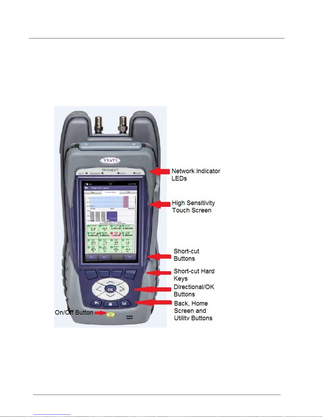
Exploring the front panel
The controls and LEDs on the front panel, shown in Figure 1, are used to
operate the OneExpert CATV, set up tests, and view data.
Figure 1 OneExpert CATV front panel
The following sections describe each of the controls and LEDs on the front
panel.
Page 26

Chapter 1 Quick To u r
Exploring the front panel
OneExpert CATV User’s Guide
22121055-001, Rev000 Page 3
Status LEDs
The controls and LEDs on the front panel, shown in Figure 1, are used to
operate the OneExpert CATV, set up tests, and view data detailed in
Table 5.
Table 5. Status LEDs
LED Function
Sync Reports the status of modem synchronization.
–
Blinking green indicates that the modems are
training.
–
Solid green indicates that the modems are
synchronized (reached Showtime).
Network Indicates the status of network connectivity.
–
Blinking green indicates that the unit is acquiring
an IP address.
–
Solid green indicates frames an IP address has
been acquired.
–
Blinking amber indicates a timeout - the unit was
unable to acquire an IP address.
–
If the Frame LED is not illuminated, the network is
not active (either the unit is not connected or it is
logged off.
NOTE: The S ync and Network LEDs alternately blink green when in sleep
mode (power saving mode).
Error Solid red indicates error and alarm conditions. The type
of error varies depending on the application.
Page 27

Chapter 1 Quick To u r
Exploring the front panel
OneExpert CATV User’s Guide
Page 4 22121055-001, Rev000
Statu s LEDs (Continued)
LED Function
Batt A multi-color LED that indicates the battery status.
–
Solid green indicates that either the battery charge
is higher than 30%, or that an external source is
powering the unit.
–
Solid amber indicates that the battery is getting
low, the charge is between 10% and 30%.
Solid red indicates that the battery charge is critically
low, less than 10%. An audible beep occurs 30
seconds before shutdown.
L
CD
The LCD is a touchscreen that operates similar to a mobile device (such
as an iPad or similar Android device), where you swipe to go to the next
page or zoom in/out by pinching or opening your fingers.
Function keys
Use the function keys to select screen-specific opti ons or to select pop-up
menus associated with each key.
Page 28
Chapter 1 Quick To u r
Exploring the front panel
OneExpert CATV User’s Guide
22121055-001, Rev000 Page 5
Arrow keys
Use the arrow keys to navigate through menu selections.
OK key
Use the OK key to accept a changed setting or to proceed to the
next
menu.
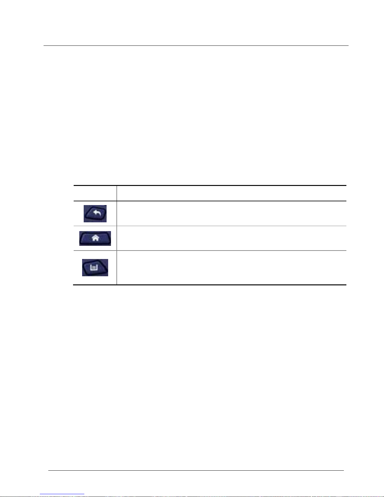
System keys
Under the Navigation arrow keys, there are three system keys:
Key Description
Back/Cancel – Exit a menu or to go back to the previous
menu.
Home – Return to the main/home screen.
Tray – Launch the Tray menu. From the Tray Menu you can
save test reports, turn on/off Bluetooth, or enable/disable
Remote Operation.
Power key
Use the power key to turn the OneExpert CATV power on or off by
pressing the key until the unit beeps.
Page 29

Chapter 1 Quick To u r
Exploring the top panel
OneExpert CATV User’s Guide
Page 6 22121055-001, Rev000
Exploring the top panel
The OneExpert CATV RF port connectors are located on the top end of
the instrument.
Figure 2 OneExpert CATV Top Panel
These connectors are used to connect the OneExpert CATV to the system
for the testing and analysis of the signal reaching the customer premises
–
The Port 1 connector is used to connect an RF cable for US/DS
Analysis of the incoming signal.
–
The Port 2 connector is used to measure the RF Ingress on the
incoming signal.
Port 1 – RF US/DS Analysis
Port 2 – RF Ingress Port
Page 30
Chapter 1 Quick To u r
Exploring the bottom panel
OneExpert CATV User’s Guide
22121055-001, Rev000 Page 7
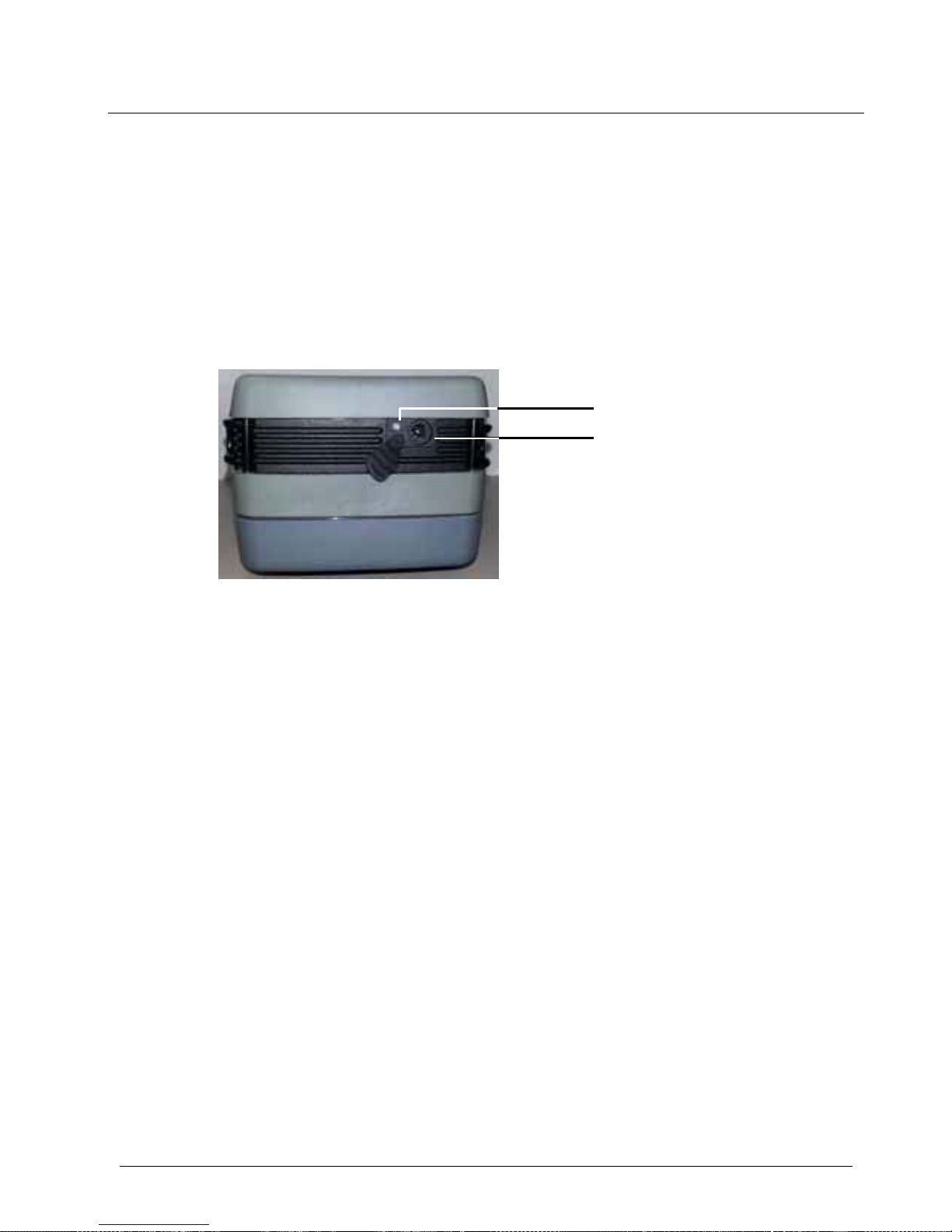
Exploring the bottom panel
The OneExpert CATV +12VDC connector is located on the bottom end of
the instrument. This connector is used to power the OneExpert CATV and
to charge the lithium battery inside.
Figure 3 OneExpert bottom panel
The Charge LED, located next to the charger connector, is a multi-color
LED that indicates the charge status.
–
Solid green indicates that charging is complete.
–
Slow flashing red indicates that the battery charge is critically low, less
than 10%.
–
Fast flashing red indicates that the charging was suspende d due to a
fault and user intervention is necessary (for example, the wrong
charger is attached).
–
Solid red indicates that the charging was suspended due to
overheating. The unit can continue to run, no user intervention
necessary.
–
Solid amber indicates that the battery is charging.
Charge LED
DC powe
r
input
Page 31

Chapter 1 Quick To u r
Exploring the right side panel
OneExpert CATV User’s Guide
Page 8 22121055-001, Rev000
Exploring the right side panel
The connector panel, located on the right side of the instrument (under a
rubber flap), provides the ports required to connect your OneExpert CATV
to the line under test. When the connectors are not being used, place the
rubber flap over the connector panel to keep out dust and rain.
Connector panel
Figure 1 Right Side connector panel shows the connector panel for an
ONX620.
Figure 1 Right Side connector panel
Page 32

Chapter 1 Quick To u r
Exploring the right side panel
OneExpert CATV User’s Guide
22121055-001, Rev000 Page 9
USB connectors
The USB connectors are used for connecting Smart IDs, exporting test
results to a flash drive, or for performing firmware upgrades from a flash
drive.
Network connectors
Two Ethernet/Network ports are used to connect to Ethernet networks to allow
Ethernet testing (such as hub flash, port discovery, and ping), synchronize with
StrataSync, upgrade software, a nd remotely connect to the OneExpert.
Rings
The rings on the corners of the instrument can be used to attach a carry
strap.
Page 33

Chapter 1 Quick To u r
Navigating the user interface
OneExpert CATV User’s Guide
Page 10 22121055-001, Rev000
Navigating the user interface
The user interface of the OneExpert is designed to be intuitive and easy to
use. The LCD is a touchscreen that operates similar to a mobile device
(such as an iPad or similar Android device), where you swipe to go to the
next page or zoom in/out by pinching or opening your fingers. Using the
interface, you can view test results, set up the OneExpert, and configure
test parameters.
When you power up the OneExpert CATV, the HomeScreen appears.
The Home Screen indicates the options enabled on your instrument.
The header area provides the battery status (using a graphic of the battery
charge remaining), indicates whether the adapter is plugged in (using a
lightning bolt next to the battery), and displays the current time.
Page 34

Chapter 1 Quick To u r
Navigating the user interface
OneExpert CATV User’s Guide
22121055-001, Rev000 Page 11
Expanding a menu
Each item on the main menu is a collapsible menu.
You can expand each of the collapsible menu items.
To expand a menu
Do one of the following:
•
Touch the triangle on the right.
•
Use the arrow navigation keys to high-light the desired menu item
(CATV is highlighted in Figure 3 above), and then press the OK key.
The triangle to the right of the menu item points down after the menu is
expanded.
Page 35

Chapter 1 Quick To u r
Navigating the user interface
OneExpert CATV User’s Guide
Page 12 22121055-001, Rev000
Selecting a menu option
After you expand a collapsible menu, you can select a specific option.
To select a menu option
Do one of the following:
•
Touch the menu option.
•
Use the arrow navigation keys to highlight the desired menu option,
and then press the OK key.
The option is selected.
Entering data
Some menu options may require you to enter text or numbers (for
example, test settings or user information). The process is similar to data
entry on a mobile device.
To enter data
1
Touch the desired item.
A data entry box appears.
2
Tap in the box.
Page 36

Chapter 1 Quick To u r
Navigating the user interface
OneExpert CATV User’s Guide
22121055-001, Rev000 Page 13
A keypad appears on the screen.
3
Use keypad to enter the data.
–
To switch from letters to numbers, use the button in the lower left
(123 or ABC).
–
On the alphabetic keypad, the second key, the up arrow, is the
shift key.
–
On the numeric keypad, the second key (1/2) allows you to move
among multiple numeric screens.
–
The left pointing arrow with the x in it is the backspace key.
4
Touch the enter/return key (the fourth system key) on the screen
keypad or press the OK key.
The data is entered and stored.
Page 37

Chapter 1 Quick To u r
Navigating the user interface
OneExpert CATV User’s Guide
Page 14 22121055-001, Rev000
Creating or removing a shortcut
If you have a test or function that you use frequently, you can make it a
shortcut. You can create up to four shortcuts.
To create a shortcut
•
Touch and hold the icon for the function and then drag it to the bottom
of the screen to create a shortcut.
To remove a shortcut
•
Touch and hold the icon and then drag it off of the shortcut bar.
Page 38

OneExpert CATV User’s Guide
22121055-001, Rev000 Page 15
Utilities
This chapter describes utilities found in the System menu and the Tr a y
menu. The utilities are used to set up you r instrument, upgrade th e software, specify user information, generate job tickets and test reports,
capture screen shots, and perform other tasks. To p i c s discussed in this
chapter include the following:
•
Accessing system utilities on page 17
•
Setting up your instrument on page 17
•
Changing screen and power settings on page 20
•
Setting the volume on page 24
•
Specifying the location for s aved files on page 25
•
Specify ing user information on page 25
•
Restoring factory defaults on page 26
•
Establishing network connections on page 27
•
Establishing a Bluetooth connection on page 36
•
Updating the instrument’s firmware on page 37
•
Page 39

Chapter 2 Utilities
Navigating the user interface
OneExpert CATV User’s Guide
Page 16 22121055-001, Rev000
•
Synchronizing to the StrataSync server on page 46
•
Managing files on page 51
•
Viewing the User’s Guide on your instrument on page 54
•
Remotely operating the instrument on page 54
Page 40

Chapter 2 Utilities
Accessing system utilities
OneExpert CATV User’s Guide
22121055-001, Rev000 Page 17
Accessing system utilities
System utilities are accessed using the System Settings menu or T ra y
menu on your instrument.
Display ing the System Settings menu
Using the items provided on the System Settings menu, you can turn on
remote operation (via VNC Viewer), change screen and power settings,
control the volume, view Hardware and Software versions, view Options
purchased with the ONX 620 meter and complete USB Software updates.
T o display the Sys tem Settings menu
1
From the Main menu, touch the System menu item.
Figure 2 System Menu
The System Menu appears.
2
Touch the System Settings icon.
Page 41

Chapter 2 Utilities
Accessing system utilities
OneExpert CATV User’s Guide
Page 18 22121055-001, Rev000
The System Settings menu appears.
Figure 4 System Settings menu
Page 42

Chapter 2 Utilities
Accessing system utilities
OneExpert CATV User’s Guide
22121055-001, Rev000 Page 19
Displaying the Tra y menu
Using the icons provided on the T ra y menu (shown in Figure 5), you can
specify settings required for network, WiFi, and Bluetooth® connectivity,
control the volume on your instrument, and manage job tickets and reports.
Yo u can also take screen shots of the user interface, and review a PDF of
this on your instrument.
T o di spla y the T ray menu
•
Do one of the following:
–
Press the Tray function key
–
Swipe downward from the top of the screen.
Figure 5 Tray Menu
Page 43

Chapter 2 Utilities
Setting up your instrument
OneExpert CATV User’s Guide
Page 20 22121055-001, Rev000
Setting up your instrument
Yo u setup your instrument using the items provided on the System Settings
menu (shown in Figure 4 on page 18) and the Tray menu (shown in Figure
5 on page 19).
Configuring international settings
The International Settings menu is used to select the language, lo cal units
of measurement, and other international settings. There are two ways to
select international settings:
•
Select a preset cou nt ry. This automatically configures the international
settings as appropriate for the selected country.
•
Configure each setting individually. If you are not in one of the preset
countries, or if the settings aren’t appropriate for your situation, you
can configure each setting indi vid ually .
After selecting a country or configuring each individual setting, you must
reboot the instrument for the international settings to take effect. The
settings will be retained when you turn your instrument off.
T o confi gure international settings
1
Go to the System Settings menu (see Displaying the System Settings
menu on page 17), then select International Settings.
The International Settings menu appears.
2
Optional. Select Country to select a preset country.
Selecting a specific country will automatically change the settings as
appropriate for that country. For example, selecting France will
automatically set the language to Francais, the measurement system
to
Metric (for example, the unit of distance will be expressed in meters
and the cable size will be expressed in millimeters), the unit of
temperature to Celsius.
Page 44

Chapter 2 Utilities
Setting up your instrument
OneExpert CATV User’s Guide
22121055-001, Rev000 Page 21
3
If necessary, change the settings for Language, Keyboard,
Measurement System, Temperature Units, Time Zone, and Cable
Terminology by doing the following:
a
Touch the menu item that corresponds to the setting.
b
Select the value for the setting from the list.
4
Press the Back/Cancel function key to exit the menu.
5
Reboot the instrument (turn off the power, then turn it back on).
The international settings are configured and the user interface is localized.
Setting the date and time
The OneExpert has an internal clock that you can set to provide accurate
time stamp s for test results. The following procedure describes how to
set
the date and time.
T o set the date and time
1
Go to the System Settings menu (see Displaying the System Settings
menu on page 17), then select Date and Time.
The Date and Tim e Settings menu appears.
2
Set the time by doing the following:
a. Touch Time.
b. Turn the dials to select the hour, minutes, and AM or PM.
Press OK.
3
Set the date by doing the following:
a Touch Date.
b
Use the arrows to set the month and year.
c Select the day on the calendar.
d Press Set.
Page 45

Chapter 2 Utilities
Setting up your instrument
OneExpert CATV User’s Guide
Page 22 22121055-001, Rev000
4
Specify the Date Format by doing the following:
a Touch Date Format.
b Select MM/DD/YYYY or DD/MM/YYYY .
5
Specify the Time Format by doing the following:
a Touch Time Format.
b Select 12 Hour or 24 Hour.
6
To change the Time Zone, do the following:
a Touch Time Zone.
b Select the time zone.
7
If Daylight Savings Time (DST) is used in your area, touch the DST
Used checkbox to enable DST. A check mark will appear indicating that
DST is enabled.
8
To control Time Synchronization, do the following:
a Touch Time Synchronization.
b If synchronization is required, select NTP. If synchronization is
not
needed, select None.
When enabled, Network Tim e Protocol (NTP) synchronizes your
system clock to a central t ime ser v er.
9
If you enabled NTP, specify the following:
a NTP Server Address type (IPv4 Address, IPv6 Address, DNS
Name)
b NTP Server (the address of the server where the instruments gets
the time, for example 0.us.pool.ntp.org)
The instrument indicates whether it is synchronized with the NTP
server under Synchronization S tate .
10
Press the Back/Cancel function key to exit the menu.
The date and time are set.
Page 46

Chapter 2 Utilities
Changing screen and power settings
OneExpert CATV User’s Guide
22121055-001, Rev000 Page 23
Changing screen and power settings
The Screen and Power Management menu allows you to adjust the brightness of the backlight, set the backlight timeout, and set the amount of idle
time to wait before the instrument automatically powers itself off when
operating on battery power.
Idle time refers to time during which no keys are pressed and no line
activity takes place. So, if you set the Power Off Delay to 5 minutes and
then begin a 15 minute test, the unit will not power down during the test
because there is activity on the line (as a result of the test).
NOTE:
The OneExpert CATV will not automatically power down when
connected to the AC adapter
T o specify sc reen and power management setti ngs
1
Go to the System Settings menu (see Displaying the System Settings
menu on page 17), then select Screen & Power Management.
2
To set the backlight settings, do the following:
a Touch Backlight.
b Either touch the + / - buttons on the screen or swipe your finger
across the bar to move the line on the bar, adjusting the bright-
ness of the backlight.
3
To set the amount of time to wait before dimming the backlight, do the
following:
a Touch Backlight Timeout.
b Select the amount of time to wait before the backlight dims.
Page 47

Chapter 2 Utilities
Setting the volume
OneExpert CATV User’s Guide
Page 24 22121055-001, Rev000
4
To set the amount of idle time to wait before the instrument
automatically powers itself off, do the following:
a Touch Power Off Delay.
b Select the amount of idle time to wait before the instrument
automatically powers itself off.
5
Press the Back/Cancel function key to exit the menu. The screen and
power management settings are specified.
Setting the volume
Yo u can control the volume of your instrument using the Vo l um e icon on
the Tray menu.
T o set the vol ume on your instrument
1
Display the Tray menu, and then touch Volume.
The volume scroll bar appears.
2
Either touch the + / - buttons on the screen or swipe your finger across
the bar to move the line on the bar, adjusting the volume.
3
Press the Back/Cancel function key to exit the menu. The volume is set
on your instrument.
Page 48

Chapter 2 Utilities
Specifying the location for saved files
OneExpert CATV User’s Guide
22121055-001, Rev000 Page 25
Specifying the location for saved files
You can setup your instru ment to automatically save test results, screenshots, or other files to the instrument’s file system, a connected USB drive,
or both (if applicable).
T o specify the location for s aved files
1
Go to the System Settings menu (see Displaying the System Settings
menu on page 17), then select Save Location.
2
Touch the circle to the left of File-system, USB device (when available), or Both (when applicable).
3
Press the Back/Cancel function key to exit the menu. Files will be
saved to the location (and/or device) specified.
Specifying user information
The User Information menu allows you to enter specific information related
to the technician using the OneExpert CATV. This includes the technician
name and ID, and the Strata Sy nc account ID. This information is used
when synchronizing with the St rataS ync se rve r.
NOTE:
AvalidStrataSyncTechID/UserIdandAccountIDmustbeenteredin
ordertosynchronizeyourinstrumenttotheStrat aS ync server.
Page 49

Chapter 2 Utilities
Restoring factory defaults
OneExpert CATV User’s Guide
Page 26 22121055-001, Rev000
T o specify user information
1
Go to the System Settings menu (see Displaying the System Settings
menu on page 17), then select User Information.
2
Specify the user’s first and last name, workgroup, company, email
address, and other information.
3
Press the Back/Cancel function key to exit the menu. The user
information is specified.
Restoring factory defaults
The following procedure describes how to reset the OneExpert CATV to
factory default settings.
NOTE:
Restoring factory defaults resets test application settings and system
settings (such as brightness, contrast, and volume), and powers down
the unit.
T o restore system and test application settings to factory
defaults
1
Go to the System Settings menu (see Displaying the System Settings
menu on page 17), then select Restore Factory Settings.
A prompt appears indicating that all settings will be restored to
factory
defaults.
2
Press the OK key to acknowledge the prompt and restore the factory
default settings.
Settings are restored to their factory default values. Y ou must reboot
your
instrument for the factory defaults to take effect.
Page 50

Chapter 2 Utilities
Establishing network connections
OneExpert CATV User’s Guide
22121055-001, Rev000 Page 27
Establishing network connections
Yo u can establish wired network and intranet connections, and wireless
WiFi connections to your instrument to update the firmware, transfer files,
synchronize to the Strat aSync ser ver, or control the instrument’s user interface remotely.
Enabling network connectivity
Before you establish a connection to an Ethernet or WiFi network, you must
enable network connectivity on your instrument.
T o enable network connectivity
Go to the Tra y menu (see Displaying the Tr ay menu on page 19).
Touch the Network icon. The icon will be gre en when connectivity is
enabled.
Network connectivity is enabled.
NOTE:
The Bluetooth and WiFi interfaces cannot be ON at the same time.
Page 51

Chapter 2 Utilities
Establishing network connections
OneExpert CATV User’s Guide
Page 28 22121055-001, Rev000
Establishing an Ethernet connection
Yo u must have an Ethernet LAN cable to establish an Ethernet connection
to your instrument.
T o establish an Ethernet connection to the instrument
1
Using an Ethernet cable, connect the instrument to the LAN:
a Connect one end of the Ethernet cable to the OneExpert CATV
Ethernet connector located on the side panel (see Figure 1 on page
8).
b Connect the other end of the Ethernet cable to the LAN.
2
Verify that network connectivity is enabled (see Enabling network
connectivity on page 27).
Go to the System menu (see System Menu on page 17), then touch
Network.
The System Network menu appears.
3
Select the Ethernet button at the bottom of the menu.
Items appear that allow you to specify settings that are requi red to
connect to the LAN.
4
Select Network Mode and then specify the network mode: IPv4, IPv6,
or IPv4/IPv6 Dual Stack. Depending on the Network Mode, you have
one or more additional settings to specify.
Page 52

Chapter 2 Utilities
Establishing network connections
OneExpert CATV User’s Guide
22121055-001, Rev000 Page 29
5
Configure the instrument’s IP settings to match the LAN settings by
doing one of the following:
–
If you specified IPv4 as your network mode, specify the following
settings:
IPv4 Address Mode Setting
DHCP No additional settings.
Static IPv4 Address
–
Enter the instrument’s IP address
(which
will be used when accessing
the provider
network).
IPv4 Netmask
–
Enter the netmask address to
indicate
whether the packets are to
be routed to
other networks or sub-
networks.
IPv4 Gateway
–
Enter the address for the gateway
that is
used to route packets that are
not on the
same subnet.
IPv4 DNS Server
–
Enter the address of the DNS serv e r.
Page 53

Chapter 2 Utilities
Establishing network connections
OneExpert CATV User’s Guide
Page 30 22121055-001, Rev000
–
If you specified IPv6 as your network mode, specify the following
settings:
IPv6 Address Mode Setting
DHCPv6 No additional settings.
Stateless IPv6 DNS Address Mode
–
DHCPv6. If you select DHCPv6,
there are no additional settings to
specify.
–
Manual. If you select Manual, you
must
specify the IPv6 DNS Server
address.
IPv6 DNS Server
–
Enter the address of the DNS server.
Manual IPv6 Global Address
–
Enter the instrument’s IPv6 address
to the
access the global network.
IPv6 Subnet Prefix Length
–
Enter the subnet prefix length.
IPv6 Gateway
–
Enter the address for the gateway
that is
used to route packets that are
not on the
same subnet.
IPv6 DNS Address Mode
–
DHCPv6. If you select DHCPv6,
there are no additional settings to
specify.
–
Manual. If you select Manual, you
must
specify the IPv6 DNS Server
address.
IPv6 DNS Server
–
Enter the address of the DNS server.
Page 54

Chapter 2 Utilities
Establishing network connections
OneExpert CATV User’s Guide
22121055-001, Rev000 Page 31
–
If you specified IPv4/IPv6 Dual Sta ck as your netwo rk mode,
specify the following settings:
IP Dual Stack
Address Modes
Setting
DHCP No additional settings.
Static See IPv4 Address Mode on page 29.
Stateless See IPv6 Address Mode on page 30.
Manual See IP Dual Stack Address Modes above.
6
Display the Tray menu, and then touch Network to establish the
connection.
The instrument establishes an Ethernet connection to the LAN.
Establishing an RF Connection
Yo u must have an RF coax cable to establish an R F connection to the
internet from your instrument.
T o establish an RF connection to the instrument
To Sync via RF Port 1 please use the “Connection” app in the CATV
section at the top of the Home screen to establish a live connection with
the CMTS prior to syncing to StataSync.
Page 55

Chapter 2 Utilities
Establishing network connections
OneExpert CATV User’s Guide
Page 32 22121055-001, Rev000
Establishing a WiFi connection
The WiFi option allows you to establish a WiFi connect ion to a wireless
network to 1) synchronize your instrument to the St rat aSy nc serv er, 2)
export reports, screen shots, or job ti ckets (using FTP ), or 3) update the
firmware on your instrument.
Adding a WiFi network profile
If an access point does not broadcast its Service Set Identifier (SSID), you
can manually create a profile for a WiFi n etwork. Yo u r instru ment will save
the profile, then automatically authenticate and establish a connection to
the network if 1) network conne ctivity is enabled, 2) the network’ s access
point is in range, and 3) the network is determined to provide the best available access point (based on signal strength and/or encryption sup ported).
The instrument can save up to 32 WiFi network profiles.
NOTE
Yo u instrument will automatically save a profile after successfully
connecting to a new WiFi network.
Page 56

Chapter 2 Utilities
Establishing network connections
OneExpert CATV User’s Guide
22121055-001, Rev000 Page 33
T o add a WiF i network profile
1
Verify that network connectivity is enabled (see Enabling network
connectivity on page 27).
2
Go to the System menu (see System Menu on page 17), then touch
Network.
The System Network menu appears.
3
Select the WiFi button at the bottom of the menu.
Yo u r instrument immediately scan s for WiFi networks, and lists each
network as an item.
4
Touch Add Network.
The Add WiFi Network menu appears.
5
Specify the following settings:
Setting Value
SSID
The SSID (Service Set Identifier) of the WiFi
network.
Password The password required to authenticate to the
network. A password is not required if Key
Management is set to None.
Key Management Open, WE P, or WPA/WPA2 Personal
Page 57

Chapter 2 Utilities
Establishing network connections
OneExpert CATV User’s Guide
Page 34 22121055-001, Rev000
Setting Value
Network Mode IPv4, IPv6, or IPv4/IPv6 Dual Stack.
Depending on the Network Mode, you have one
or more additional settings to spe ci fy . For details,
see:
–
IPv4 Address Mode on page 29.
–
IPv6 Address Mode on page 30.
–
IP Dual Stack Address Modes
on page 31.
6
Return to the System Network menu.
The network that you created a profile for is listed on the menu.
Connecting to a WiFi network
Yo u can manually connect to any compatible WiFi network that is within
range of your instrument, and for which you have authorized access (and
a password for authentication).
T o establish a WiF i connection
1
Verify that network connectivity is enabled (see Enabling network
connectivity on page 27).
2
Go to the System, then touch Network.
The System Network menu appears.
3
Select the WiFi button at the bottom of the menu.
Page 58

Chapter 2 Utilities
Establishing network connections
OneExpert CATV User’s Guide
22121055-001, Rev000 Page 35
Yo u r instrument immediately scan s for WiFi networks, and lists each
network as an item.
–
A lock indicates that authentication is required to connect to a
network.
–
Saved, In Range indicates that a profile for the network has been
saved on your instrument, and a connection can be e stablished to the
instrument.
–
Saved, Out of Range indicates that a profile for the network ha s been
saved on your instrument, but the network is out of range
(and
therefore, a connection cannot be established).
–
Incompatible indicates that a connection cannot be established to a
network.
–
Connected indicate s that the instrument has already established a
connection to the network.
The instrument automatically connects to the network determined to
provide the best available access point (based on signal strength and/or
encryption supported).
4
If you want to connect to a different network, touch the SSID of the WiFi
network. A screen appears with items that allow you to specify
advanced settings (profile settings), forget a saved network, or connect
to the network.
5
Touch Connect.
–
Messages appear briefly on the indicating that the instrument is
performing a four-way handshake, then authenticating to the
network.
–
The status of the connection (Network Up), and details concerning
the connection (IP address, netmask, ga te way , and
DNS server)
appear at the top right of the menu.
The instrument is connected to the WiFi network.
Page 59

Chapter 2 Utilities
Establishing a Bluetooth connection
OneExpert CATV User’s Guide
Page 36 22121055-001, Rev000
Establishing a Bluetooth connection
The Bluetooth® option allows communication with a paired m obile device
or SmartID+.
Enabling Bluetooth connectivity
Before you establish a connection to Bluetooth device, you must enable
Bluetooth connectivity on your instrument.
T o enable Bluetooth connectivity
1
Go to the Tray menu (see Displaying the Tray menu on page 19).
2
Touch the Bluetooth icon. The icon will be green when connectivity is
enabled.
Bluetooth connectivity is enabled.
NOTE:
The Bluetooth and WiFi interfaces cannot be ON at the same time.
Connecting to a Bluetooth de v ic e
Yo u can establish a conn ection to any Bluetooth device that is within range
of your instrument, and for which you have authorized access.
T o establish a Bluetooth connection
1
Go to the System Settings menu (see Displaying the System Settings
menu on page 17), then select Bluetooth.
The Bluetooth Settings menu appears.
2
Tou c h the box next to Enabled. A check mark appears.
Page 60

Chapter 2 Utilities
Updating the instrument’s firmware
OneExpert CATV User’s Guide
22121055-001, Rev000 Page 37
3
Touch Scan for devices.
The instrument scans for Bluetooth devices, then lists the devices on
the menu.
4
Select the device to connect to.
–
If the instrument successfully authenticates to the device, a
message appears indicating that pairing was successful.
–
If the instrument does not successfully authenticate to the device,
a message appears indicating that pairing failed.
If pairing was successful, you can use the instrument with the paire d
device.
Updating the instrument’s firmware
All ONX units should be upgraded to the latest production software
release – available through StrataSync (or your VIAVI representative).
Software (SW) and Firmware (FW) releases are the best way to ensure
your VIAVI OneExpert ONX is functioning at its best.
The OneExpert CATV firmware can be upgraded in the field using 1) a
wired network or intranet connection, 2) a WiFi connection, or 3) a USB
drive with a copy of the firmware.
To download the firmware
If you are using a USB drive for upgrades, you can download the firmware
from StrataSync.
The preferred method of downloading the firmware is via StrataSync.
To update the firmware
1
Connect the OneExpert to the AC charger adapter to ensure an
uninterrupted supply of power during the update.
WARNING: ELECTRICAL SHOCK
Page 61

Chapter 2 Utilities
Updating the instrument’s firmware
OneExpert CATV User’s Guide
Page 38 22121055-001, Rev000
Electrical shock may result in serious injury or death. Be sure the AC
adapter is connected to the correct voltage mains. Do not use outdoors
or in wet locations. Use only the AC adapter supplied with the tester.
2
Do one of the following:
3
Establish a wired Ethernet connection, to Port 1, from your instrument to
the intranet or network (see Establishing an Ethernet connection on
page 28).
–
Establish a WiFi connection from your instrument to the network
with the firmware update (see Establishing a WiFi connection on
page 32).
–
Download the firmware update to a USB drive.
a Click on the top do wnload icon (as shown) to get the latest
update.
b Copy the downloaded file ONXCBL.xxx.xxx.xxx.oxu to the
root directory of a USB thumb drive.
c Press Cancel once the download has completed and you
have placed the file on the USB thumb drive.
Page 62

Chapter 2 Utilities
Updating the instrument’s firmware
OneExpert CATV User’s Guide
22121055-001, Rev000 Page 39
4
Go to the System Settings menu (see Displaying the System Se ttings
menu on page 17), then select one of the following:
–
Network Software Update. Select this if you are updating the
firmware using a network (Ethernet or WiFi) connection.
–
USB Update. Select this if you are updating the firmware using a
USB drive.
5
Do the following:
Source of update Do this
USB drive NOTE: Be certain no Ethernet cables are
plugged in when performing USB Upgrade.
–
Connect the drive with the firmware to the
USB connector on the right panel. The
OneExpert will auto-detect the USB drive.
–
Touch USB So f twa r e Upd ate and then
select
the de s i r e d firmware file on the USB
drive.
–
Press the Update button and the upgrade
will begin.
–
Press Update again to confirm.
–
The meter will power off when the upgrade
is complete.
Page 63

Chapter 2 Utilities
Updating the instrument’s firmware
OneExpert CATV User’s Guide
Page 40 22121055-001, Rev000
Figure 3 USB Upgrade Process
StrataSync
–
From the ONX-CATV home screen,
select the System Menu and then the
Network icon.
–
Verify the ONX has a valid IP address
(should have been changed from the
default address of 192.168.0.*)
–
Navigate back to the Home Screen and
select System Menu and then the
StrataSync icon.
–
Enter the following information
• StrataSync Account ID –
Determined at Setup
• Interface – Ethernet ; DOCSIS.
If set to DOCSIS, firmware upgrades
will be skipped – without warning.
NOTE: This setting does not select
the communication interface –
Ethernet or RF/DOCSIS. This setting
must be made via the CATV screen Connection icon.
• Server Address -
stratasync.jdsu.com or
stratasync.viavisolutions.com
• Server Port = 443
Page 64

Chapter 2 Utilities
Updating the instrument’s firmware
OneExpert CATV User’s Guide
22121055-001, Rev000 Page 41
Select Start when all data entered
–
ONX will connect to StrataSync and
determine there is a “Software Update
Available” - Select OK.
–
Software packages will be confirmed –
Select Update.
SW update will proceed. The unit will
Power off completely after completion.
Update process will take 10-15 minutes
based on the size of the update file and
connection speed.
Figure 4 StrataSync Upgrade Process
5
If the update doesn’t start automatically, select the Update system key.
The update status appears on the screen.
Page 65

Chapter 2 Utilities
Updating the instrument’s firmware
OneExpert CATV User’s Guide
Page 42 22121055-001, Rev000
The instrument automatically turns power of f after the update is complete
NOTE:
Verify that there are no connected Ethernet cables before
attempting USB Firmware upgrade of the ONX-CATV.
Page 66

Chapter 2 Utilities
Updating the instrument’s firmware
OneExpert CATV User’s Guide
22121055-001, Rev000 Page 43
Troubleshooting Upgrade Process
No IP address
1. Navigate to the System
Network Profiles screen
(
System
menu-
Network
icon).
2. When IPV4 State= “In
Use By Application”, via
the Home Screen,
navigate to Ethernet
menu and select
Ethernet icon
3. Select the
Network Setup
button at the bottom.
This dis-associates the
Ethernet port to the
Ethernet testing
function.
4. Press the Back button
on the unit and cycle
power to the meter.
5. When the meter returns
to the Home Screen,
restart the upgrade
process.
IP address of ONX or gateway starts with 192.168.0
Syncing to StrataSync server for an upgrade or running a DOCSIS test with this IP
address has a higher chance of failure. The ONX uses this address internally which may
cause the data to be delivered to an incorrect device.
Page 67

Chapter 2 Utilities
Updating the instrument’s firmware
OneExpert CATV User’s Guide
Page 44 22121055-001, Rev000
There are two recommended solutions tro this situation-
1. Reconfigure the router to any other IP address grouping. For example 192.168.1.*
or 10.0.0.*.
2. Perform the update via USB.
Viewing hardware/software versions and options
The following procedure describes how to view the status of available
options and the hardware and software versions for your instrument.
To view options and hardware/software versions
1.
Go to the System Settings menu (see Displaying the System Settings
menu on page 17).
2.
Do one of the following:
–
To review hardware and software versions, select Hardware/
Software Revisions.
The revisions of the internal components and the software
versions appear. The instrument’s unique unit ID number also
appears on this screen. You will need the unit ID if you are adding
options.
–
To review the status of available options, select Options.
A list of available options appears with the status for each option
(Enabled or Upgradeable).
Hardware and software versions, and available options have been
reviewed.
Page 68

Chapter 2 Utilities
Updating the instrument’s firmware
OneExpert CATV User’s Guide
22121055-001, Rev000 Page 45
Installing options
The following procedures describe how to install options on you r
instrument. Options can be installed from a USB stick onto which the
options have been stored.
The preferred method of option installation is via StrataSync (see”
Synchronizing to the StrataSync Server” below.
To install options from USB
1. Before installing options, upgrade to the latest firmware (see “Updating
the instrument’s firmware” on page 50).
If you received the option file by email (instead of a USB drive), save
the option file to a USB drive.
2. Insert the USB drive into the OneExpert.
3. From the main menu, touch the System menu item. The collapsible
menu opens
4. Select USB File Browser.
5. Highlight the option file on the USB drive.
6. Select File Option, and then Copy to Internal.
The file is copied to the internal file browser.
7. Press the Home button.
8. Optional. Touch the System menu and then select File Browser to
verify that the option file was copied to the unit.
9. Reboot the instrument (turn off the power, then turn it back on).
The option is installed.
Page 69

Chapter 2 Utilities
Synchronizing to the StrataSync server
OneExpert CATV User’s Guide
Page 46 22121055-001, Rev000
Synchronizing to the StrataSync server
StrataSync® is a hosted, cloud-based software application that provides
VIAVI instrument asset, configuration, and test-data management. StrataSync manages inventory, test results, and performance data anywhere
with browser-based ease and improves technician and instrument
efficiency. This service is provided free of charge for the first year.
Features include the following:
•
Tracking ownership of the OneExpert CATV
•
Pushing certain configuration settings to the OneExpert CATV
•
Receiving certain configuration setting from the OneExpert CATV
•
Adding and/or removing software options on the OneExpert CATV
•
Updating the software on the OneExpert CATV
•
Updating the software on the modem
•
Cloninge a device (create a “golden” unit)
To obtain the latest configuration settings, software options and updates,
and ownership registration information, the OneExpert CATV can
synchronize with a VIAVI server via the internet. The synchronization also
stores any user files saved on the unit to the StrataSync server.
This procedure should be undertaken immediately upon receipt of the unit
and on a regular (daily) basis thereafter to ensure that the unit is as up-todate as possible and to allow all user information to be backed up. Before
attempting to synchronize with StrataSync, please confirm your server
settings with your manger or your company's IT organization.
To sync with StrataSync
1. If you haven’t already done so, specify the user information on the
User Info menu (see Specifying user information on page 25). A valid
account ID must be entered in order to synchronize with the
StrataSync server.
2. Connect the ONX to an active internet connection - Ethernet cable
from Cable modem or router to ONX Port 1 RJ-45 connector.
Page 70

Chapter 2 Utilities
Synchronizing to the StrataSync server
OneExpert CATV User’s Guide
22121055-001, Rev000 Page 47
3. Verify the ONX has a valid IP Address.
a From the System menu (see System Menu on page 17), select
Network.
b Check the IP addresses displayed.
i
The ONX IP address is configured as 192.168.0.*
ii
The Gateway should be configured as 192.168.0.1
4. From the System menu (see System Menu on page 17), touch the
Strata-Sync icon.
The StrataSync settings menu appears.
5. Specify the settings.
Setting Description
System
SettingsStrataSync
Account ID
Enter the account identification number. Only
change this if necessary.
StrataSync Tech ID/
User ID
Enter the technician/user identification number.
Interface Ethernet- indicates ??
DOCSIS- When set, firmware update will not
occur. There is no on-screen reminder of this
fact.
To sync via RF Port 1 please use the
“Connection” app in the CATV section at the top
of the Home screen to establish a live
connection with the CMTS prior to syncing to
StataSync.
Server Address Enter the DNS address for the server.
The default address is:
“https://stratasync.viavisolutions.com”
Server Port Enter the server port number.
The default port is: 443
6
Touch the Start button.
Page 71

Chapter 2 Utilities
Synchronizing to the StrataSync server
OneExpert CATV User’s Guide
Page 48 22121055-001, Rev000
As the process runs, the sync state is displayed on the screen.
•
Upon synchronization with the StrataSync server, the unit will
send to the server the following information:
–
The unit’s serial number.
–
The unit’s hardware information - constituent assembl i es and
their revision levels.
–
The unit’s MAC address.
–
The unit’s User settings - name (user/technician) and ID.
–
The last calibration date of the Copper board (if applicable;
this is not provided for the ONX-580A, which does not have a
Copper board).
–
Software update milestones (includes status and warnings, if
applicable)
If the configuration information contained on the server is
newer than that on the unit, the server will be considered to be
the most up-to-date.
•
The server will then send any files to the unit being synchronized
that it determines are newer than those on the unit.
•
The unit will then send any Reports, Configuration profiles, XML
results, screen shots, etc. that have been saved on the unit since
the last configuration.
•
The server then applies any applicable Options to the unit.
NOTE:
If an Option Code was entered as a part of synchronization, power must
be cycled to the unit to complete the process and initialize the option.
•
Copy (“clone”) the configuration settings for the base unit, as well
as any company-specific configurations such as custom filters,
web bookmarks, and FTP passwords. This can be used to create
a “golden” unit.
Page 72

Chapter 2 Utilities
Synchronizing to the StrataSync server
OneExpert CATV User’s Guide
22121055-001, Rev000 Page 49
•
Lastly, if any upgrades are available, the user will be informed of
their availability and asked to verify their desire to receive the
upgrade.
When synchronization is complete, the Status will indicate “Sync
Complete”. The unit may be disconnected from the server.
Generating reports
The Save Report icon (provided on the Tra y menu) allows you to create
reports based on the configuration settings and test results for the currently
active test. This only works for Ethernet tests
NOTE:
Yo u must be running an active test or the Save Reports icon will be
disabled (gray).
Saving a report
If you are currently running a test, you can save test results, configuration
settings, and graphs as a report.
T o save a report
1. If you haven’t already done so, access the Tray menu and then touch
Save Report.
A Save Report window appears.
2. Do the following:
a Enter the name of the report. The default file name uses the type
of
test followed by a three-digi t number that increments with
each file
saved (for example, cablecheck001 or DSL002).
b Specify the format (PDF , XML, or HTML).
3. If you want to include custom fields in the report, enable, then specify
values for the fields.
4. Do one of the following:
–
T o view the report imm edi at ely , touch Save and View.
Page 73

Chapter 2 Utilities
Synchronizing to the StrataSync server
OneExpert CATV User’s Guide
Page 50 22121055-001, Rev000
–
T o save the report without viewing it, touch Save.
The current test results, configuration settings, and, if applicable, graphs
and custom report fields are saved as a report. If you indicated that you
want to view the report imm ediately , the report output also appears on your
instrument’s LCD.
Tec hn ici a n report values will be saved until you change them. Custom
report fields need to be completed for every test report saved, but you can
apply the values specified the last time you saved the repo rt.
Viewing a report
Yo u can view saved reports on the LCD of your instrument.
NOTE:
If the View Report icon is disabled (gray), there are no reports saved on
your instrument.
T o view a report
1. Access the Tray menu and then touch View Report.
A View Report window appears, showing all of the sa ved reports.
2. Select a report to view.
The report appears on the screen.
Capturing a scree n shot
In addition to or instead of a report, you can capture an image of the current
screen.
To capture a screen shot
1. Access the Tray menu and then touch Screen Shot.
2. Enter a name for the screen shot.
The PNG file is saved to the internal file manager.
Page 74

Chapter 2 Utilities
Managing files
OneExpert CATV User’s Guide
22121055-001, Rev000 Page 51
T o cap tur e the t ray menu or a popup menu
If you wish to capture the tray menu itself, or if you wish to capture a popup
menu, do the following:
•
Press and hold the tray key for 5 second s.
Managing files
The OneExpert file browser is used to open, rename, c o p y , or delete
saved result files, screen shots, or other files stored on your instrument or
on a USB flash drive that is connected to your instrument. Both browsers
function in the same mann er.
Accessing the file browser
The File Browser and USB File Browser menus are both accessed from the
System menu.
To access the file browser
•
From the System menu (see System Menu on page 17), do one of the
following:
–
T o view and manage files on your instrument, touch the File
Browser button.
–
T o view and manage files on a connected USB flash drive, touch
the USB File Browser button.
The File Browser menu appears listing all folders (or files).
Page 75

Chapter 2 Utilities
Managing files
OneExpert CATV User’s Guide
Page 52 22121055-001, Rev000
Selecting files or folde rs
T o select one or more files or fold er s
1. Go to the file browser (see Accessing the file browser on page 51).
2. Use the up and down arrow keys to move among folders or files. to
see the contents of a folder, touch the folder.
3. Do one of the following:
–
T o select a single file or fo l d e r, touch the che ckbox to the l ef t of
the file or folde r.
–
T o select multiple files or folders (for example, if you want to copy
multiple files to USB, or upload multiple files using FTP/
HTTP),
touch the checkbox to the left of each folde r.
The files or folders are selected.
Opening files or folde rs
T o open a file or fol de r
1. Go to the file browser (see Accessing the file browser on page 51).
2. Select the file or folder (see Selecting files or folders above).
3. Touch Open.
The contents of the folder appear or the file is displayed on the screen.
Page 76

Chapter 2 Utilities
Managing files
OneExpert CATV User’s Guide
22121055-001, Rev000 Page 53
Copying and pasting files or fold ers
T o copy files or folders
1. Go to the file browser (see Accessing the file browser on page 51).
2. Select the file or folder (see Selecting files or folders on page 52).
3. Press the File Options system ke y , and then do one of the following:
–
Select Copy, navigate to another folder or drive, press the File
Options system key, and then select Paste.
–
Select either Copy to USB if you are using File Browser or Copy
to Internal if you are using the USB File Browser.
The file is copied and the File Browser menu appears.
Uploading files using FTP/HTTP
T o upload files
1. Go to the file browser (see Accessing the file browser on page 51).
2. Select the file or folder (see Selecting files or folders on page 52).
3. Press the File Options system key , and then select Upload FTP/HTTP.
The Upload settings appear.Specify the Upload URL, Username, and
Password.
4. Touch Apply.
The upload starts.
When the upload finishes, a message appears stating that the selected
files were uploaded. Press OK to close the message.
Page 77

Chapter 2 Utilities
Viewing the User’s Guide on your instrument
OneExpert CATV User’s Guide
Page 54 22121055-001, Rev000
Viewing the User’s Guide on you r instrument
Using the instrument’s PDF vi ewe r, you can view the User’s Guide o n the
instrument. The file must be on a USB stick or copie d to the OneExpert.
1. Under the System menu (see System Menu on page 17), select File
Browser.
2. Navigate to find the xxxxxxxxr00x_OneExpert_Users-
Guide.pdf file.
3. To u c h the file name to open it.
The PDF reader application launches with the User’s Guide o pen.
Remotely operating the instrument
The optional Remote Operation features allows you to access the
OneExpert CATV user interface from a PC or laptop computer through a
virtual network connection (VNC), connecting over an Ethernet interface or
WiFi network.
T o use this feature, 1) you must have a VNC viewer program on the PC, 2)
the OneExpert CATV must be connected to the same network as the PC or
laptop, and 3) you must know the IP address of the OneExpert CATV.
Establishing a VNC connection involves the following tasks:
•
Establishing a connection between the instrument and a PC or laptop
–
See “Establishing an Ethernet connection” on page 41
–
See “Establishing a WiFi connection” on page 45
•
Enabling Remote Operation using VNC
•
Control the instrument using a PC keyboard
Each of these operations is described in the following sections.
Page 78

Chapter 2 Utilities
Remotely operating the instrument
OneExpert CATV User’s Guide
22121055-001, Rev000 Page 55
Viewing the device interface on the PC
After you have established an Ethernet or WiFi connection, you must
launch the VNC program to view the device interfa ce.
T o view the d ev ic e interface on the PC
1. Launch the VNC viewer on the PC.
2. In the viewer’s server address field, type the OneExpert CATV IP
address, and then select OK.
3. A password entry box appears.
4. Enter the VNC password (found on the Remote Operation menu) and
then select OK.
5. The OneExpert CATV user interface appears in the VNC viewer.
6. T o use a PC or laptop keyboard with the OneExpert user interface, see
Using a PC keyboard on page 56.
7. If the message, “Failed to connect to server” appears, the VNC
viewer
was not able to communicate with the OneExpert. If this
happens, try
the following solutions:
–
Make sure you are using the correct IP address for the OneExpert
–
From the PC or laptop, ping the OneExpert IP address to verify
the network link is working. If the link is not working,
restart the
OneExpert and repeat step 1 through step 2.
Page 79

Chapter 2 Utilities
Remotely operating the instrument
OneExpert CATV User’s Guide
Page 56 22121055-001, Rev000
Using a PC keyboard
After you have connected to the OneExpert CATV from a laptop or PC using
the VNC viewe r, you can use the computer’s mouse or keyboard to control
the OneExpert CATV Table 6 shows how the PC/laptop keys map to the
OneExpert CATV keypad.
Table 6. PC/laptop to OneExpert CATV key map
PC/Laptop key OneExpert Keys
F1 through F4 Correspond to the OneExpert system keys
F5 Home
F6 Tray menu
F7 AutoTest
Escape Cancel
Enter OK
VNC availability
The VNC program can control the following functions:
•
In Ethernet TE, you can do a ping, trace route and similar data te sts,
but you cannot change any data settings.
Ending a remote operation session
T o end a remote operation sessi on, either exit the VNC session on the PC/
laptop or turn the OneExpert off and then on again (power cycle).
Page 80

Chapter 2 Utilities
Remotely operating the instrument
OneExpert CATV User’s Guide
22121055-001, Rev000 Page 57
Page 81

OneExpert CATV User’s Guide
22121055-001, Rev000 Page 58
Menus and Workflow
This chapter describes the layout of the Main Screen of the OneExpert,
the selection options on the main screen and the workflow that is common
to most operations performed on the OneExpert. Topics discussed in this
chapter include the following:
•
Main Screen Selections on page 59
•
Testing Workflow on page 60
•
Review Test Results on page 63
Page 82

Chapter 3 Menus and Work fl ow
Main Screen Selections
OneExpert CATV User’s Guide
22121055-001, Rev000 Page 59
Main Screen Selections
The menu selections shown on the Home Screen that are covered in this
manual are:
CATV
For detailed information on this menu item, see CATV Testing on
page 66.
Ethernet
For detailed information on this menu item, see Ethernet Testing
on page 80.
WiFi
For detailed information on this menu item, see WiFi Tests on
page 96.
System
For detailed information on this menu item, see Displaying the
System Settings menu on page 17.
Page 83

Chapter 3 Menus and Work fl ow
Testing Workflow
OneExpert CATV User’s Guide
Page 60 22121055-001, Rev000
Testing Workflow
Choose Test
Choose the test you want to run by selecting the icon on the CATV
screen.
Choose test location
Select what part of the circuit is being tested. Many tests are optimized for
different parts of the installation-
•
Tap
•
Ground Block
•
CPE
Connect the Meter
For every test, the Setup screen includes a graphic showing the proper o r
a suggested connection arrangement.
Often notes on where a port is to be connected are supplied.
Enter Work Order
All test Setups have the option to assign the test to a Work Order Number.
This is highly recommended because the data analysis performed by the
OneExpert CATV compares to previous data from the current location as
defined by the Work Order number. Activated Work Order ID also allows
faster Auto Channel plan build functionality.
On each Setup screen, the button below the heading Work Order ID will
show the currently loaded Work Order.
To Run a test assigned to a previously loaded Work Order
1
On Setup screen for the test you are running, select the Work Order ID
button.
Page 84

Chapter 3 Menus and Work fl ow
Testing Workflow
OneExpert CATV User’s Guide
22121055-001, Rev000 Page 61
The currently loaded Work Order is the default.
2
Select any listed Work Order from the list of loaded work orders.
3
Select Enter.
To Run a test at location and create a new Work Order
1
On Setup screen for the test you are running, select the Work Order ID
button.
2
Add new Work Order.
3
Enter the name of the new Work Order (up to 50 characters)
4
Select Enter.
To Run a test without entering any Work Order in a new
location
1
On Setup screen for the test you are running, select the Work Order ID
button.
The following screen will usually appear.
Page 85

Chapter 3 Menus and Work fl ow
Testing Workflow
OneExpert CATV User’s Guide
Page 62 22121055-001, Rev000
2
Press the Clear Session button to ignore the warning and run the test
anyway.
Page 86

Chapter 3 Menus and Work fl ow
Review Test Results
OneExpert CATV User’s Guide
22121055-001, Rev000 Page 63
Review Test Results
The results of the tests appear in one of two formats – Dashb oard and
Live Analysis.
Dashboard
Every dashboard will have multiple screen areas displaying results for
different circuit sections tested or different types of test performed on the
circuit. The dashboard display usually provides a graph of the results of
the test and more detailed data about the test available on additional
screens.
Drill Down
Many dashboard areas will have additional detailed information available.
This additional information is accessed by double tapping the desired
screen area.
Pass/Fail Indication
When results are within the parameters expected for a test, the
background on the screen area will change to light green and a pass
icon will appear in the upper left corner of the screen area.
When results are not within the parameters expected for a test, the
background on the screen area will change to light red and a
fail icon will appear in the upper left corner of the screen area.
Page 87

Chapter 3 Menus and Work fl ow
Review Test Results
OneExpert CATV User’s Guide
Page 64 22121055-001, Rev000
Live Analysis
Live analysis displays will show the status of various parameters of the
signal being monitored in real-time.
Page 88

Chapter 3 Menus and Work fl ow
Review Test Results
OneExpert CATV User’s Guide
22121055-001, Rev000 Page 65
Measurement Pass/Fail Indication
When a specific data point being measured is within the parameters
expected for a test, the background on that measurement display area will
change to light green and a pass icon will appear in the upper left
corner of the measurement display area.
When a specific data point being measured is not within the paramet ers
expected for a test, the background on that measurement display area will
change to light red and a fail icon will appear in the upper left corner
of the measurement display area.
If the overall result of the test is not acceptable a red X will appear in the
header of the screen.
Page 89

OneExpert CATV User’s Guide
22121055-001, Rev000 Page 66
CATV Testing
This chapter describes the CATV tests that are accessed via the CATV
menu item on the main screen of the OneExpert CATV. Topics discussed
in this chapter include the following:
•
CATV Test Options on page 67
•
OneCheck on page 67
•
Ingress Scan on page 69
•
ChannelCheck om page 71
•
DOCSIS Check on page 73
•
Spectrum on page 75
•
Quick Check on page 77
Page 90

Chapter 4 CATV Testing
CATV Test Options
OneExpert CATV User’s Guide
22121055-001, Rev000 Page 67
CATV Test Options
The expanded CATV menu item is shown below.
The functions accessible from the expanded CATV menu are-
•
OneCheck test
•
Ingress Scan test
•
Channel Check test
•
DOCSIS Check test
•
Connection
•
CATV Settings
•
Spectrum test
•
Quick Check test
OneCheck
OneCheck conducts comprehensive and automated testing of Ingre ss,
Downstream & DOCSIS with SessionExpert™ from a chosen demarcation
point utilizing both ports on the ONX 620.
The Session Expert feature provides solutions to the problems discovered.
Page 91

Chapter 4 CATV Testing
OneCheck
OneExpert CATV User’s Guide
Page 68 22121055-001, Rev000
Setup
To run OneCheck Test
1
Select the OneCheck icon from beneath the CATV menu header.
The “Select a test location” window appears.
2
Select the icon for the demarcation point (Tap, Ground Point or CPE)
being tested.
A graphic showing the appropriate connection schematic for this test
will appear.
3
Assign this test to a saved work order (optional but recommended).
Select the button below Work Order ID and the list of available work
orders will appear. Select one
4
Start the test by selecting the Start button at the bottom of the screen.
Results
The results screen dashboard is com prised of four areas for each of the
demarcation points:
•
Upstream Ingress
•
Downstream Full Scan
•
DOCSIS Test
•
Session Expert
Page 92

Chapter 4 CATV Testing
Ingress Scan
OneExpert CATV User’s Guide
22121055-001, Rev000 Page 69
Each area has an associated detailed results view accessi ble by double
tapping within the dashboard area.
Navigate the results screen using the touchscreen and directional buttons.
Saving Results
OneCheck will automatically save the results of the last t est run. To
capture these specific results prior to retesting, hit the Save button and
then name the file.
For a more detailed discussion of the results produced by this test, see the
Results chapter.
Ingress Scan
The Ingress Scan conducts the same test done by OneCheck, checking
Upstream for interference into the signal.
To run an Ingress Scan
1. Select the Ingress Test icon from beneath the CATV menu header.
The “Ingress Scan Setup” window appears. The grap hic displayed
shows that Port 2 should be connected to the upstream test point.
Page 93

Chapter 4 CATV Testing
Ingress Scan
OneExpert CATV User’s Guide
Page 70 22121055-001, Rev000
2. Assign this test to a saved work order (optional but recommended).
Select the button below Work Order ID and the list of available work
orders will appear. Select one.
3. Start the test by selecting the Start button at the bottom of the screen.
Page 94

Chapter 4 CATV Testing
ChannelCheck
OneExpert CATV User’s Guide
22121055-001, Rev000 Page 71
Results
For a detailed discussion of the results produced by this test, see the
Results chapter.
ChannelCheck
The Channel Check test provides real-time analysis of Downstream QAM
and Analog Carriers.
The ChannelCheck test conducts the same test done by OneCheck
Upstream checking for interference into the signal. It analyzes OFDM
carriers including multiple DS profiles.
Channel check can also be used to quickly check levels and signal
performance.
To run ChannelCheck
1
Select the ChannelCheck icon from beneath the CATV menu header.
The “ChannelCheck Setup” window appears.
2
Select the desired demarcation point to be tested- Tap, Ground Block or
CPE.
A graphic showing the appropriate connection schematic for this test
will appear along with appropriate instructions for the port to be used.
Page 95

Chapter 4 CATV Testing
ChannelCheck
OneExpert CATV User’s Guide
Page 72 22121055-001, Rev000
3
Assign this test to a saved work order (optional but recommended).
4
Select the button below Work Order ID and the list of available work
orders will appear. Select one.
5
Start the test by selecting the Start button at the bottom of the screen.
Results
For a detailed discussion of the results produced by this test, see the
Results chapter.
Saving results
To capture a snapshot of the results for review, press the Stop button.
To save for later review, press the Save button and then give them a
name.
Page 96

Chapter 4 CATV Testing
DOCSIS Check
OneExpert CATV User’s Guide
22121055-001, Rev000 Page 73
DOCSIS Check
The DOCSIS Check test provides real-time analysis of DOCSIS services.
The DOCSIS Check test shows only the DOCSIS carriers to allow you to
focus on HSD services.
DOCSIS Check allows you to troubleshoot and analyze Downstream and
Upstream DOCSIS carriers including OFDM and channel bonding.
To run DOCSIS Check
1
Select the DOCSIS Check icon from beneath the CATV menu header.
The “DOCSISCheck” setup window appears.
2
Select the desired demarcation point to be tested- Tap, Ground Block or
CPE.
A graphic showing the appropriate connection schematic for this test
will appear along with appropriate instructions for the port to be used.
3
Assign this test to a saved work order (optional but recommended).
4
Select the button below Work Order ID and the list of available work
orders will appear. Select one.
Page 97

Chapter 4 CATV Testing
DOCSIS Check
OneExpert CATV User’s Guide
Page 74 22121055-001, Rev000
4. Start the test by selecting the Start button at the bottom of the screen.
Results
For a detailed discussion of the results produced by this test, see the
Results chapter.
Saving results
To capture a snapshot of the results for review, press the Stop button.
To save for later review, press the Save button and then give them a
name.
Page 98

Chapter 4 CATV Testing
Spectrum
OneExpert CATV User’s Guide
22121055-001, Rev000 Page 75
Spectrum
The Spectrum test provides a real-time spectral display of the incoming
signal.
To run Spectrum test
1. Select the Spectrum icon from beneath the CATV menu header.
The “Spectrum Setup” window appears.
2. Select the desired demarcation point to be tested- Tap, Ground Block or
CPE.
A graphic showing the appropriate connection schematic for this test
will appear along with appropriate instructions for the port to be used.
3. Assign this test to a saved work order (optional).
4. Select the button below Work Order ID and the list of available work
orders will appear. Select one.
5. Start the test by selecting the Start button at the bottom of the screen.
The live spectrum analysis graph will appear for your inspection.
Page 99

Chapter 4 CATV Testing
Spectrum
OneExpert CATV User’s Guide
Page 76 22121055-001, Rev000
Results
For a detailed discussion of the results produced by this test, see the
Results chapter.
Page 100

Chapter 4 CATV Testing
Quick Check
OneExpert CATV User’s Guide
22121055-001, Rev000 Page 77
Quick Check
The Quick Check test provides the ability to quickly check for signal
presence on a small number of manually-added channels.
To run Quick Check
1. Select the Quick Check icon from beneath the CATV menu header.
The “Quick Check Setup” window appears.
2. Select the desired demarcation point to be tested- Tap, Ground Block or
CPE
A graphic showing the appropriate connection schematic for this test
will appear along with appropriate instructions for the port to be used.
3. Assign this test to a saved work order (optional but recommended).
4. Select the button below Work Order ID and the list of available work
orders will appear. Select one.
5. Configure the carrier to be checked by adding or removing the carrier
frequency and type.
6. Start the test by selecting the Start button at the bottom of the screen.
 Loading...