

Page 1

Operating Manual
BN 2303/98.11
2018.04
English
Optical Laser Sources
-36/-37/-38
OLS-34/-35/
Page 2

Please direct all inquiries to your local Viavi sales company. The
addresses can be found at:
www.viavisolutions.com/en-us/contact-sales-expert
A description of additional instrument features can be found at:
www.viavisolutions.com/en-us/products/network-test-and-certification
Copyrights
This product or parts of this product are based on recommendations
and/or standards from the standardization section of the International
Telecommunication Union – ITU-T and/or the European
Telecommunications Standards Institute – ETSI. These recommendations
and standards are subject to the proprietary rights of these
organizations. It is not permitted to copy ITU-T recommendations or
ETSI standards fully or in part and/or to pass them on to third parties
without prior written permission from ITU-T and/or ETSI.
Copyright
© Copyright 2016 Viavi Solutions Inc. All rights reserved.
Viavi and the Viavi logo are trademarks of Viavi Solutions Inc.
All other trademarks and registered trademarks are the property of their
respective owners.
Viavi Solutions Deutschland GmbH
Arbachtalstraße 5, D-72800 Eningen u. A.
Order number: BN 2303/98.11
Issue: 2018.04
Previous issue: 2016.01
Notes:
Changes may be made to specifications, designations and delivery
information.
Page 3

CONTENTS
CONTENTS
INTRODUCTION . . . . . . . . . . . . . . . . . . . . . . . . . . . . . . . . 5
OLS-34/-35/-36/-37/-38 Optical Laser Sources . . . . . . . . . 5
Operating manual update. . . . . . . . . . . . . . . . . . . . . . . . . . . . 6
Symbols used in this operating manual . . . . . . . . . . . . . . . . 7
SAFETY INFORMATION . . . . . . . . . . . . . . . . . . . . . . . . . . . 9
Warning symbols on the device. . . . . . . . . . . . . . . . . . . . . . . 9
Proper use . . . . . . . . . . . . . . . . . . . . . . . . . . . . . . . . . . . . . . . . . 9
Laser safety . . . . . . . . . . . . . . . . . . . . . . . . . . . . . . . . . . . . . . . 10
Battery operation . . . . . . . . . . . . . . . . . . . . . . . . . . . . . . . . . . 10
Ventilation . . . . . . . . . . . . . . . . . . . . . . . . . . . . . . . . . . . . . . . . 11
GETTING STARTED . . . . . . . . . . . . . . . . . . . . . . . . . . . . . 12
Unpacking the device. . . . . . . . . . . . . . . . . . . . . . . . . . . . . . . 12
Device overview OLS-34/-35 . . . . . . . . . . . . . . . . . . . . . . . . 13
Device overview OLS-36 . . . . . . . . . . . . . . . . . . . . . . . . . . . . 15
Power supply . . . . . . . . . . . . . . . . . . . . . . . . . . . . . . . . . . . . . . 16
OPERATION . . . . . . . . . . . . . . . . . . . . . . . . . . . . . . . . . . 19
Switching the device on/off . . . . . . . . . . . . . . . . . . . . . . . . . 19
Display elements. . . . . . . . . . . . . . . . . . . . . . . . . . . . . . . . . . . 19
Select Wavelength . . . . . . . . . . . . . . . . . . . . . . . . . . . . . . . . . 20
Changing the port . . . . . . . . . . . . . . . . . . . . . . . . . . . . . . . . . 21
Enabling signal modulation . . . . . . . . . . . . . . . . . . . . . . . . . 21
Auto-Lambda mode. . . . . . . . . . . . . . . . . . . . . . . . . . . . . . . . 21
Multi-Lambda mode . . . . . . . . . . . . . . . . . . . . . . . . . . . . . . . 22
MAINTENANCE . . . . . . . . . . . . . . . . . . . . . . . . . . . . . . . 23
Cleaning the test port . . . . . . . . . . . . . . . . . . . . . . . . . . . . . . 23
Cleaning the instrument . . . . . . . . . . . . . . . . . . . . . . . . . . . . 24
SPECIFICATIONS . . . . . . . . . . . . . . . . . . . . . . . . . . . . . . 25
OLS-34 . . . . . . . . . . . . . . . . . . . . . . . . . . . . . . . . . . . . . . . . . . . 25
OLS-35 . . . . . . . . . . . . . . . . . . . . . . . . . . . . . . . . . . . . . . . . . . . 25
OLS-36 . . . . . . . . . . . . . . . . . . . . . . . . . . . . . . . . . . . . . . . . . . . 26
OLS-37 . . . . . . . . . . . . . . . . . . . . . . . . . . . . . . . . . . . . . . . . . . . 27
OLS-38 . . . . . . . . . . . . . . . . . . . . . . . . . . . . . . . . . . . . . . . . . . . 27
General specifications . . . . . . . . . . . . . . . . . . . . . . . . . . . . . . 29
ORDERING INFORMATION . . . . . . . . . . . . . . . . . . . . . . . 30
Devices . . . . . . . . . . . . . . . . . . . . . . . . . . . . . . . . . . . . . . . . . . . 30
OLS-34/-35/-36/-37/-38 3
Page 4

CONTENTS
Accessories . . . . . . . . . . . . . . . . . . . . . . . . . . . . . . . . . . . . . . . 32
4 OLS-34/-35/-36/-37/-38
Page 5

1 INTRODUCTION
OLS-34/-35/-36/-37/-38
Optical Laser Sources
The Test Sets are specially designed for high performance
testing of all systems, i.e. broadband, PONs, and Gigabit
Ethernet.
Battery operation from two AA batteries and the robust, shockproof design provide long operating time in the field even under
tough conditions. AC line operation via a separate AC adapter
and the USB interface ensure ease of use in the laboratory or
production environment.
Differences between the devices
OLS-34/-35/-36/-37/-38 OPTICAL LASER SOURCES
1 INTRODUCTION
The OLS-34/-35/-36/-37/-38 family covers all the modes,
wavelengths and fiber types needed. The table below lists the
differences between the devices:
OLS-34
Model
BN...
2303/01 MM 50/125 850/1300 nm SC/PC, FC/PC
Fiber type Wavelengths Connector type
OLS-35
Model
BN...
2303/11 SM 9/125 1310/1550 nm SC/PC, FC/PC
2303/15 SM 9/125 1310/1550 nm LC/PC
Fiber type Wavelengths Connector type
OLS-36
Model
BN...
2303/21 MM 50/125
OLS-34/-35/-36/-37/-38 5
Fiber type Wavelengths Connector type
SM 9/125
850/1300 nm
1310/1550 nm
SC/PC, FC/PC
Page 6

1 INTRODUCTION
OPERATING MANUAL UPDATE
OLS-37
Model
BN...
2303/41 SM 9/125 1310/1490/1550 nm SC/PC, FC/PC
Fiber type Wavelengths Connector type
OLS-38
Model
BN...
2303/51 SM 9/125 1310/1550/1625 nm SC/PC, FC/PC
Fiber type Wavelengths Connector type
Test adapters
The OLS-34/-35/-36/-37/-38 is looped into the test
configuration using test adapters which are available for all
common connector systems (e.g. FC, ST).
Operating manual update
If the operating instructions about features provided by your
device are missing, please visit the Viavi web site to check if
additional information is available.
To download the latest operating instructions:
1. Visit the Viavi website at
www.viavisolutions.com/en-en/products/network-test-andcertification.
2. Select your model from the product line or use the search
function.
3. Open the download area and download the operating
instructions if available.
6 OLS-34/-35/-36/-37/-38
Page 7
SYMBOLS USED IN THIS OPERATING MANUAL
1 INTRODUCTION
Symbols used in this operating manual
Various elements are used in this operating manual to draw
attention to special meanings or important points in the text.
Symbols and terms used in warnings
The following warnings, symbols and terms are used in this
document in compliance with the American National Standard
ANSI Z535.6-2011:
CAUTION
Follow the instructions carefully to avoid damage to or
destruction of the instrument.
CAUTION
Follow the instructions carefully to avoid a low or medium risk
of injury to persons.
WARNING
Follow the instructions carefully to avoid severe injury to
persons.
DANGER
Follow the instructions carefully to avoid death or severe
injury to persons.
High Voltage
Follow the instructions carefully to avoid damage to the
instrument or severe injury to persons.
This safety instruction is given if the danger is due to high
voltage.
Laser
Follow the instructions carefully to avoid damage to the
instrument or severe injury to persons.
This safety instruction is given if the danger is due to laser
radiation. Information specifying the laser class is also given.
OLS-34/-35/-36/-37/-38 7
Page 8

1 INTRODUCTION
SYMBOLS USED IN THIS OPERATING MANUAL
Warning format
All warnings have the following format:
WARNING
Type and source of danger
Consequences of ignoring the warning
► Action needed to avoid danger.
The following character formats are used in this operating
manual:
√
►
1.
2.
Italics
Bold
type face
Tex t in
blue
Requirement
This requirement must be met first; e.g.
√ The system is switched on.
Instruction
Follow the instructions given (the numbers indicate the order
in which the instructions should be followed); e.g.
► Select mode.
Result
Indicates the result of following an instruction; e.g.
The page opens.
Pages, controls, and display elements
Screen pages, controls, and display elements are indicated in
bold type.
Cross references
Cross references are indicated in blue type. When using the
PDF version, just click on the blue text to skip to the cross
reference.
[STORE]
8 OLS-34/-35/-36/-37/-38
Device keys
Device keys are indicated within square brackets.
Page 9

2 SAFETY INFORMATION
Warning symbols on the device
Warning symbols indicating a potential hazard
► A warning symbol on the device indic at es a p ote nt ia l haz ard.
In all cases where the unit is labeled with a warning symbol,
the operating manual must be consulted to learn more
about the nature of the potential hazard and any actions that
have to be taken.
Proper use
This instrument is intended for measurements on optical fiber
devices and systems.
WARNING SYMBOLS ON THE DEVICE
2 SAFETY INFORMATION
► Please make sure the device is not operated outside the
permitted conditions or for a purpose other than the one it
was developed for.
► Always make sure that the device is in good condition before
switching it on.
OLS-34/-35/-36/-37/-38 9
Page 10
2 SAFETY INFORMATION
LASER SAFETY
Laser safety
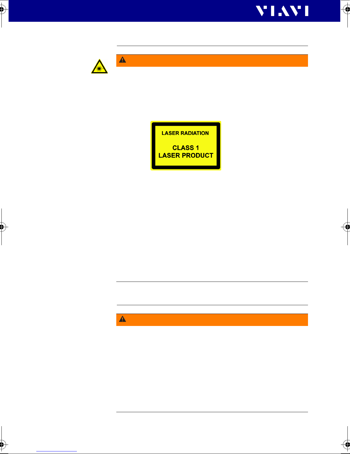
WARNING
Dangerous laser radiation
Laser radiation can cause irreparable damage to the eyes
and skin.
This device is a Class 1 laser product according to DIN EN
60825-1:2003 and EN 60825-1:2007.
Observe the following instructions when working with this
device and laser systems in general:
► Connect all optical fibers before switching on the radiation
source.
► Switch off the laser source before disconnecting the optical
fibers.
► Never look directly into the output of a laser source or into
an optical fiber connected to it.
► Always cover unused ports.
► Observe the normal precautions for working with laser
radiation and follow any local regulations.
Battery operation
WARNING
Explosion danger
Short-circuiting the batteries can result in overheating,
explosion or ignition of the batteries and their surroundings.
10 OLS-34/-35/-36/-37/-38
► Never short-circuit the battery contacts by touching both
contacts simultaneously with an electrically conductive
object.
► Only use AA size dry batteries or rechargeable batteries.
► Take care to insert the batteries correctly.
Page 11
2 SAFETY INFORMATION
VENTILATION
WARNING
Explosion danger
Dry batteries must not be recharged.
► The OLS-34/-35/-36/-37/-38 does not have a recharge
function for rechargeable batteries, so there is no danger
when using dry batteries.
► Read the manual of the external charging device.
Ventilation
CAUTION
Insufficient ventilation
Insufficient ventilation can damage the instrument or
adversely affect its function and safety.
► Ensure adequate ventilation when operating the instrument.
OLS-34/-35/-36/-37/-38 11
Page 12

3 GETTING STARTED
UNPACKING THE DEVICE
3 GETTING STARTED
Unpacking the device
Packing material
We suggest that you keep the original packing material. It is
designed for reuse (unless it is damaged during shipping). Using
the original packing material ensures that the device is properly
protected during shipping.
Checking the package contents
Your device is shipped with the following accessories:
• 2 dry batteries AA
• Operating manual
•Belt bag
Checking for shipping damage
After you unpack the device, check to se e if it has been damaged
during shipping. This is particularly likely if the packaging is
visibly damaged. If there is damage, do not attempt to operate
the device. Doing so can cause further damage. In case of
damage, please contact your local Viavi Sales Company.
Addresses can be found at www.viavisolutions.com.
Recovery following storage/shipping
Condensation can occur if a device that is stored or shipped at a
low temperature is brought into a warm room. To prevent
damage, wait until no more condensation is visible on the
surface of the device before powering it up. Do not operate the
device until it has reached its specified temperature range and
wait until it has cooled down if the device was stored at a high
temperature (see “Ambient temperature” on page 29).
12 OLS-34/-35/-36/-37/-38
Page 13

Device overview OLS-34/-35
1
2
3
4
6
5
7
3 G
DEVICE OVERVIEW OLS-34/-35
ETTING STARTED
1 Test head cover
2 Por t
3 Device label
4 Display
5 External power supply connector
USB interface for power supply only
6 Battery compartment (on rear of the device)
7 Key pad
OLS-34/-35/-36/-37/-38 13
Page 14

3 GETTING STARTED
DEVICE OVERVIEW OLS-34/-35
Keys
First function: Press to switch the device on and off
(ECON).
Second function: Press and hold the key for more than
2 seconds to switch the device on (PERM).
Press to select a wavelength.
Press to select wavelength coding.
Select Auto-
Multi-
Single-
Press to switch the laser on and off.
P
ress to select modulation:
CW (continuous wave: permanent signal)
270 Hz
1 kHz
2 kHz
14 OLS-34/-35/-36/-37/-38
Page 15

Device overview OLS-36
1
2
3
4
6
5
7
3 G
DEVICE OVERVIEW OLS-36
ETTING STARTED
1 Te st h ea d cov er
2 Por ts (A and B)
3 Device label
4 Display
5 External power supply connector
USB interface for power supply only
6 Battery compartment (on rear of the device)
7 Key pad
OLS-34/-35/-36/-37/-38 15
Page 16

3 GETTING STARTED
POWER SUPPLY
Keys
First function: Press to switch the device on and off
(ECON).
Second function: Press and hold the key for more than
2 seconds to switch the device on (PERM).
First function: Press to select a wavelength.
Second function: Press and hold the key for more than
2 seconds to change the port.
Press to select wavelength coding.
Auto-
Multi-
Single-
Press to switch the laser on and off.
P
ress to select modulation:
CW (continuous wave)
270 Hz
1 kHz
2 kHz
Power supply
The following power sources can be used to operate the OLS34/-35/-36/-37/-38:
• two 1.5 V dry batteries (Mignon AA size, alkaline type
recommended)
• two 1.2 V NiMH rechargeable batteries (Mignon AA size)
• via the AC adapter
16 OLS-34/-35/-36/-37/-38
Page 17

3 GETTING STARTED
POWER SUPPLY
Battery operation
WARNING
Dangers when handling batteries
Handling batteries may be dangerous. Please note the
following safety instructions.
► Please note the battery operation safety information in the
section “Battery operation” on page 10.
Replacing the batteries
► Do not replace individual batteries. Always change both
batteries at the same time.
► Always use batteries of the same type; i.e. do not mix
rechargeable and non-rechargeable batteries.
Replacing batteries
The battery compartment is on the back of the device.
1. Pull down the lid to open the battery compartment.
2. Insert new batteries or replace old ones.
Caution: Take care to insert the batteries correctly. The correct
polarity is indicated by a diagram inside the battery
compartment.
3. Close the battery compartment.
4. Press [E] to switch on.
Note: The batteries cannot be recharged with the
OLS-34/-35/-36/-37/-38.
General tips on using batteries
• Always handle batteries with care.
• Do not drop or damage the batteries or expose them to
excessively high temperatures.
• Do not store rechargeable batteries for more than one or two
days at very high temperatures (e.g. in a vehicle), either
separately or fitted in the device.
• Do not leave discharged batteries in the instrument for a long
time if it is not being used.
• Do not store rechargeable batteries for more than 6 months
without recharging them at intervals.
• Avoid deep discharging of the batteries as this can cause the
cell polarity to reverse and make the battery useless.
OLS-34/-35/-36/-37/-38 17
Page 18

3 GETTING STARTED
12
34
POWER SUPPLY
Protecting the environment
Please dispose of any unwanted dry batteries and rechargeable
batteries carefully. They should also be removed from the
instrument if it is to be scrapped. If facilities in your country exist
for collecting waste or for recycling, please make use of them
rather than throwing the batteries in the normal trash. You will
often be able to return used batteries to the store where you
purchase new ones. Any dry or rechargeable batteries that you
purchased from Viavi can be returned to one of our Service
Centers for disposal.
Operation from AC power
To fit one of the mains plug adapters:
► See Fig. 1 and follow the instructions which are shown on the
packaging of the mains plug adapter.
Fig. 1 Fitting the mains plug adapter
To operate the OLS-34/-35/-36/-37/-38 from AC power:
1. Connect the Micro USB connector power cord to the
OLS-34/-35/-36/-37/-38.
2. Plug the mains plug adapter into the AC receptacle.
18 OLS-34/-35/-36/-37/-38
Page 19

4 OPERATION
Port indicators
B
A
Switching the device on/off
The OLS-34/-35/-36/-37/-38 has two power modes:
• Permanent ON (PERM):
The device is switched on permanently.
• Automatic OFF (ECON):
The device switches off 20 minutes after the last operation. This
function is only available when the device is powered from
batteries.
To switch the device on:
► Press [E] to switch on the device in ECON-Mode.
► Press and hold down [E] for more than 2 sec. to switch on
the device in PERM mode.
SWITCHING THE DEVICE ON/OFF
4 OPERATION
To switch the device off:
Press [E] to switch off the device.
Display elements
Fig. 2 Measurement display of the OLS-34/-35 (showing all available
elements)
OLS-34/-35/-36/-37/-38 19
Fig. 3 Measurement display of the OLS-36 (showing all available ele-
ments)
Page 20

4 OPERATION
SELECT WAVELENGTH
Note: During operation only one port can be active and used.
Battery status
Indi cates the b atte ry stat us. I f it i s no t show n, on ly th e
AC adapter is active.
Operation with AC adapter
PERM
ECON
Center of
display
-7 dBm
-23 dBm
Auto-
Multi-
CW
270 Hz
1 kHz
2 kHz
Power mode
•
PERM: Device remains switched on.
•
ECON: De vi ce swi tc he s o ff 20 mi nu te s af te r t he la st
operation.
Laser active
SM = Single-mode
or
MM = Multi-mode
Laser not active
Output wavelength setting
Display of the selected output wavelength.
Power output level in dBm
Automatic wavelength coding
Continuous wave or modulation frequency
Select Wavelength
With the OLS-34/-35 two wavelengths can be selected
separately. With the OLS-36 two wavelengths can be selected
separately for each optical port.
To select a wavelength:
1. Press [Auto-] to skip through the modes and select the
Single- mode.
Neither MULTI-
2. Press [] to skip through the available wavelengths:
1 2 3 1...
20 OLS-34/-35/-36/-37/-38
nor AUTO- is shown.
Page 21

4 OPERATION
CHANGING THE PORT
Changing the port
Note: Available for the OLS-36 only.
The OLS-36 provides two optical ports (A and B), of which only
one is selected. All device settings and displays refer to the
selected port.
To change the port:
► Press and hold down [] for more than 2 sec. to change the
port.
Notes:
• The settings of the deselected port are retained.
• Due to safety reasons all lasers or LEDs are deactivated when
changing the port.
Enabling signal modulation
Modulation frequencies provided by the OLS-34/-35/-36/-37/38:
• CW: continuous wave
• 270 Hz modulation
• 1 kHz modulation
• 2 kHz modulation
To select a modulation frequency:
√ Modulation cannot be changed manually when Auto-
is activated. You first must disable Auto- (see page 21).
► Press [MOD] to skip through the available modulation modes:
CW 270kHz 1kHz 2kHz CW...
Auto-Lambda mode
Auto- is a special feature developed by Viavi that allows you to
identify wavelengths automatically. To do this, the signal is
modulated at a certain frequency, which can be detected by an
Auto- equipped power meter (such as the Viavi OLP-3x-series).
To activate Auto-:
► Press [Auto-] to s ki p t hr ou gh th e mo de s a nd sel ec t t he A ut o-
mode.
The display shows AUTO-
OLS-34/-35/-36/-37/-38 21
.
Page 22

4 OPERATION
MULTI-LAMBDA MODE
Multi-Lambda mode
When Multi- mode is activated, the signal of each wavelength
is sent automatically in a loop. Each signal will be sent for a few
seconds and then skips automatically to the next wavelength.
The display shows the current wavelength.
To activate Multi-:
1. Press [Auto-] to skip through the modes and select the
Multi- mode.
The display shows MULTI-
Note: Signal modulation (270 Hz, 1 kHz, 2 kHz) cannot be
selected when Auto- is enabled.
.
22 OLS-34/-35/-36/-37/-38
Page 23

5 MAINTENANCE
WARNING
Dangerous voltage and invisible laser radiation
Maintenance or cleaning of the instrument while it is connected or operating may damage the instrument or injure
you.
► Make sure that the instrument is switched off and
disconnected from all power sources and optical radiation
sources before maintenance or cleaning.
Cleaning the test port
It is a good idea to check that the optical connections are clean
and to clean them if necessary before starting measurements.
Even very small dust particles on the end surfaces of the plugs or
in the test adapters can adversely affect the accuracy of the
measurement.
5 MAINTENANCE
CLEANING THE TEST PORT
For daily use, clean the optical interface of the instrument using
Viavi IBC cleaning tool 2.5 mm (see “Cleaning materials, power
supplies” on page 32).
To clean the test port in case of severe contamination:
1. Switch off the device.
2. Remove the test adapter from the optical connection. The
connection surface is now accessible.
3. Wipe off the connection surface using a cotton bud soaked in
isopropanol. This cleaning method is very effective and leaves
no residues.
4. Blow out the test adapter with clean compressed air (also
available in spray cans, e.g. Anti Dust Spray).
Note: Cover the optical connections with the dust cap
whenever they are not in use. This prevents them from
getting dirty.
OLS-34/-35/-36/-37/-38 23
Page 24

5 MAINTENANCE
CLEANING THE INSTRUMENT
Cleaning the instrument
If the device gets dirty through use, you can clean it using a soft
cloth moistened with a mild solution of detergent.
NOTICE
Water and cleaning fluids
The instrument may be damaged or destroyed if water or
cleaning fluids penetrate it.
► Make sure that water or cleaning fluids do not get inside the
device.
24 OLS-34/-35/-36/-37/-38
Page 25

6 SPECIFICATIONS
OLS-34
Source type LED
Fiber type Multi mode (MM) 50/125
Optical interface
•Type
•Number of optical ports
• Connectors BN 2303/01
Auto- mode yes
Modulation frequencies 270 Hz, 1 kHz, 2 kHz
Multi- mode yes
Wavelength(s) 850 nm (20 nm)
Spectral width (FWHM) < 170 nm
Output power (CW) -20 dBm
Stability
• Short term (15 min)
•Long term (8 h)
1)
6 S
PECIFICATIONS
OLS-34
PC
Interchangeable
adapter BN 2150/00.xx,
SC and FC adapters
included in scope of delivery
1300 nm (-20/+40 nm)
0.02 dB
0.05 dB
1
1) after 20 min. warm-up, at ambient temperature -10 °C to +55 °C, T = ±0.3 K
OLS-35
Source type LASER
Fiber type Single mode (SM) 9/125
Optical interface
•Type
•Number of optical ports
• Connectors
BN 2303/15
BN 2303/11
adapter BN 2150/00.xx,
included in scope of delivery
Auto- mode yes
Modulation frequencies 270 Hz, 1 kHz, 2 kHz
Multi- mode yes
Wavelength(s) 1310 nm (20 nm), 1550 nm
Interchangeable
SC and FC adapters
PC
fixed: LC
(20 nm)
1
OLS-34/-35/-36/-37/-38 25
Page 26

6 SPECIFICATIONS
OLS-36
Spectral width (FWHM) < 5 nm
Output power (CW) -7 dBm
Stability
• Short term (15 min)
•Long term (8 h)
1) after 20 min. warm-up, at ambient temperature -10 °C to +55 °C, T = ±0.3 K
1)
0.02 dB
0.05 dB
OLS-36
Source type
•Port A
•Port B
Fiber type
•Port A
•Port B
Multi-mode (MM) 50/125
Single-mode (SM) 9/125
Optical interface
•Type
•Number of optical ports
• Connectors
BN 2303/21
Interchangeable
adapter BN 2150/00.xx,
SC and FC adapters
included in scope of delivery
Auto- mode yes
Modulation frequencies 270 Hz, 1 kHz, 2 kHz
Multi- mode yes
Wavelength(s)
•Port A
850 nm (20 nm)
1300 nm (-20/+40 nm)
•Port B
1310 nm (20 nm)
1550 nm (20 nm)
Spectral width (FWHM)
•Port A
•Port B
Output power (CW)
•Port A
•Port B
Stability
1)
• Short term (15 min)
•Long term (8 h)
LED
LASER
PC
< 170 nm
< 5 nm
-20 dBm
-7 dBm
0.02 dB
0.05 dB
2
1) after 20 min. warm-up,
26 OLS-34/-35/-36/-37/-38
at ambient temperature -10 °C to +55 °C, T = ±0.3 K
Page 27

6 S
PECIFICATIONS
OLS-37
OLS-37
Source type LASER
Fiber type Single mode (SM) 9/125
Optical interface
•Type
•Number of optical ports
• Connectors
BN 2303/15
BN 2303/11
Interchangeable
adapter BN 2150/00.xx,
SC and FC adapters
included in scope of delivery
Auto- mode yes
Modulation frequencies 270 Hz, 1 kHz, 2 kHz
Multi- mode yes
Wavelength(s) 1310 nm (20 nm),
1490 nm (5nm),
1550 nm (20 nm)
Spectral width (FWHM) < 5 nm
Output power (CW) -7 dBm
Stability
1)
• Short term (15 min)
•Long term (8 h)
PC
fixed: LC
0.02 dB
0.05 dB
1
1) after 20 min. warm-up, at ambient temperature -10 °C to +55 °C, T = ±0.3 K
OLS-38
Source type LASER
Fiber type Single mode (SM) 9/125
Optical interface
•Type
•Number of optical ports
• Connectors
BN 2303/15
BN 2303/11
Interchangeable
adapter BN 2150/00.xx,
SC and FC adapters
included in scope of delivery
Auto- mode yes
Modulation frequencies 270 Hz, 1 kHz, 2 kHz
Multi- mode yes
Wavelength(s) 1310 nm (20 nm),
1550 nm (20 nm),
1625 nm (5nm)
PC
fixed: LC
1
OLS-34/-35/-36/-37/-38 27
Page 28

6 SPECIFICATIONS
OLS-38
Spectral width (FWHM) < 5 nm
Output power (CW) -7 dBm
Stability
• Short term (15 min)
•Long term (8 h)
1) after 20 min. warm-up, at ambient temperature -10 °C to +55 °C, T = ±0.3 K
1)
0.02 dB
0.05 dB
28 OLS-34/-35/-36/-37/-38
Page 29

General specifications
Calibration interval
6 SPECIFICATIONS
GENERAL SPECIFICATIONS
Recommended recalibration
interval
3 years
Power Supply
Dry batteries 2 x AA, 1.5 V
Rechargeable batteries NiMH, 2 x AA, 1.2 V
Operation from AC power with separate adapter
Operating modes permanent;
auto off
after approx. 20 min
Maximum battery run time (CW)
• OLS-34:
• OLS-35:
• OLS-36:
1) typically
1)
30 h
80 h
MM: 30 h, SM: 80 h
EMC and safety
Electromagnetic compatibility (EMC)
EN 61326-1:2006
Device safety EN 61010-1:2002
Laser safety DIN EN 60825-1:2003
EN 60825-1:2007
Ambient temperature
Operating temperature range -10 to 60 °C
Storage and shipping -40 to 70 °C
Humidity
Relative humidity up to +30 °C 5 to 95%
Absolute humidity > +30 °C 1 to 29 g/m
Occasional condensation is permissible.
Dimensions and weight
Dimensions (H x W x D) 30 x 80 x 150 mm
Weight 200 g
OLS-34/-35/-36/-37/-38 29
3
Page 30

7 ORDERING INFORMATION
DEVICES
7 ORDERING INFORMATION
Devices
OLS-34
LED Source, 850/1300 nm, MM 50/125
Interchangeable adapter BN 2303/01
FC /PC adapter
SC /PC adapter
ST /PC adapter BN 2303/04
1) included in scope of delivery
OLS-35
1)
1)
BN 2303/02
BN 2303/03
Laser Source, 1310/1550 nm, SM 9/125
Interchangeable adapter BN 2303/11
FC /PC adapter
SC /PC adapter
LC /PC adapter BN 2303/15
1) included in scope of delivery
1)
1)
BN 2303/12
BN 2303/13
OLS-36
LED Source, 850/1300 nm, MM 50/125
Laser Source, 1310/1550 nm, SM 9/125
Interchangeable adapter BN 2303/21
FC /PC adapter
SC /PC adapter
LC /PC adapter BN 2303/25
1) included in scope of delivery
1)
1)
BN 2303/22
BN 2303/23
OLS-37
Laser Source, 1310/1490/1550 nm, SM 9/125
Interchangeable adapter BN 2303/11
FC /PC adapter
SC /PC adapter
LC /PC adapter BN 2303/15
1) included in scope of delivery
30 OLS-34/-35/-36/-37/-38
1)
1)
BN 2303/12
BN 2303/13
Page 31

7 ORDERING INFORMATION
DEVICES
OLS-38
Laser Source, 1310/1550/1625 nm, SM 9/125
Interchangeable adapter BN 2303/11
FC /PC adapter
SC /PC adapter
LC /PC adapter BN 2303/15
1) included in scope of delivery
1)
1)
BN 2303/12
BN 2303/13
Calibration report
OLS-34, OLS-35, OLS-36, OLS-37, OLS-38 BN 2303/90.01
OLS-34/-35/-36/-37/-38 31
Page 32

7 ORDERING INFORMATION
ACCESSORIES
Accessories
Cleaning materials, power supplies
OCK-10
Optical cleaning kit BN 2229/90.21
IBC cleaning tool 2.5 mm ZP-FCL-0275
Cleaning tape for optical connectors BN 2229/90.07
Spare optical cleaning tape BN 2229/90.08
NiMH rechargeable batteries,
Mignon AA, 1.2 V (2 batteries required)
AC adapter SNT-505 BN 2302/90.01
Interchangeable adapter BN 2150/00.xx
BN 2229/90.21
BN 2237/90.02
32 OLS-34/-35/-36/-37/-38
Page 33

E
NVIRONMENTAL MANAGEMENT PROGRAM
Viavi Environmental Management Program
Superb performance and high quality have always characterized
Viavi datacom and telecom measurement technology products.
In this same world-class tradition, Viavi has an established,
proactive program of environmental management.
Environmental management is an integral part of Viavi’s
business philosophy and strategy requiring the development of
long-term, productive solutions to problems in the key areas of
economics, technology, and ecology.
A systematic environmental management program at Viavi is
essential in regard to environmental policy and enhances
cooperation between ourselves and our business partners.
The Viavi Environmental Management Program
considers:
Product design and manufacture
Environmental restrictions and requirements are taken into
account during planning and manufacture of Viavi products.
This attention ranges from the raw materials and finished
components selected for use and the manufacturing processes
employed, through to the use of energy in the factory, and right
on up to the final stages in the life of a product, including
dismantling.
Hazardous materials
Viavi avoids or uses with care any hazardous or dangerous
material in the manufacturing process or the end product. If the
use of a dangerous material cannot be avoided, it is identified in
product documentation and clearly labeled on the product itself.
Packaging materials
Preference is given to reusable or biodegradable singlesubstance packaging materials whenever possible.
Environmental management partnerships
Viavi encourages our customers and suppliers who take this
responsibility seriously to join Viavi in establishing their own
environmental management programs.
OLS-34/-35/-36/-37/-38 33
Page 34

E
NVIRONMENTAL MANAGEMENT PROGRAM
Recycling used products
This product complies with the European Union Waste Electrical
and Electronic Equipment directive (WEEE), 2002/96/EC. This
product should not be disposed of as unsorted municipal waste
and should be collected separately and disposed of according to
your national regulations.
In the European Union, all equipment
purchased from Viavi after 2005-08-13 can be
returned for disposal at the end of its useful life.
Measuring systems affected by this can be
recognized by the symbol on the right of a
crossed-out trash can and a black bar. This
symbol can be found either on the device or in
the accompanying documents.
Contact your local Technical Assistance Center (TAC) for return
and collection services available to you. If you would like specific
information about the Viavi Environmental Management
Program, please contact us at:
If you would like specific information about the Viavi
Environmental Management Program, please contact us at
www.viavisolutions.com.
The following page provides information with regard to the
location of restricted hazardous substances within this
equipment according to Chinese requirements.
As measuring equipment, this equipment is excluded from the
European regulations for the restriction of hazardous substances
(RoHS).
34 OLS-34/-35/-36/-37/-38
Page 35

R
₼⦌RoHS
ᇵ䟄≰㋾ℶ❐㻰㩢㘶Ⓟ丰䚕┭㽤ᇶ᧤≰㋾ℶ₩捷᧨䶻⚆᧥
棓 (Additional Information required for the Chinese Market only)
㦻棓㖘䏶 ₼⦌RoHS 䤓尐㻑広㢝ℕ㦘␂䟄≰㋾ℶ❐䘾≬∎䞷㦮棟䤓㍔⑄᧨ㄅ⒦⒉ℕℶ❐₼⚺㦘䤓㦘㹡ᇬ
㦘⹂䓸德䤓䱜伊✛㓏⦷捷ↅᇭ㦻棓抑䞷ℝℶ❐⇢✛㓏㦘揜ↅᇭ
䘾≬∎䞷㦮棟᧶
㦻㪖幕㪖㽷ℝℶ❐⇢ₙ᧨嫷㢝年ℶ❐㒥␅揜ↅ⚺㦘㦘㹡ᇬ㦘⹂䓸德᧤幵㍔屐ₚ嫷᧥ᇭ
␅₼䤓㟿ⷦⅲ嫷⦷㷲デ㝜⇫㧰ↅₚ咂⺠⦷ℶ❐䞮ℶ㡴㦮⚝㟿␔年ℶ❐㒥␅揜ↅ␔⚺㦘䤓㦘㹡ᇬ
㦘⹂䓸德ₜ↩♧㆑㒥㽓䆞ᇭ年㦮棟ₜ抑䞷ℝ庇Ⱁ䟄㻯䷘㢢劦❐ᇭ
㦘␂㷲デ㝜⇫㧰ↅ᧨庆♑屐ℶ❐䞷㓆㓚␛ᇭ
ℶ❐䞮ℶ㡴㦮庆♑屐ℶ❐䤓☮ⱚ㪰幐ᇭ
⮩䅃ℛ啾搩 (PBDE)
O
O
O
O
O
O
⮩䅃勣啾 (PBB)
O
O
O
O
O
O
⏼ↆ杻 (CR6+)
O
O
O
O
O
O
柘 (Cd)
O
O
O
O
O
O
㻭 (Hg)
O
O
O
O
O
O
㦘㹡ᇬ㦘⹂䓸德✛⏒侯
杔 (Pb)
X
O
O
O
O
O
㦘㹡ᇬ㦘⹂䓸德䤓伊⨚✛㓏⦷捷ↅ
⏒⣷ↅ
(Component)
ℶ❐⇢
(Main Product)
◿Ⓠ䟄恾㨎兓ↅ
(PCB Assemblies)
␔捷揜兎
(Internal wiring)
㣍䯉⣷
(Display)
枽䥧
(Keyboard)
⫠㠨⮥⮂榅ↅ
(Plastic case parts)
揜ↅ
(Accessories)
O᧶ⅲ嫷年捷⒕₼㓏㦘⧖德㧟㠨⚺㦘䤓年㦘㹡ᇬ㦘⹂䓸德⚺摞⇝ℝSJ/T11363-2006㪖䤓棟⋋ᇭ
X᧶ⅲ嫷年捷⒕₼㓏㦘⧖德㧟㠨⚺㦘䤓年㦘㹡ᇬ㦘⹂䓸德⚺摞浧ℝSJ/T11363-2006㪖䤓棟⋋ᇭ
OHS
OLS-34/-35/-36/-37/-38 35
Page 36

R
OHS
36 OLS-34/-35/-36/-37/-38
Page 37

Page 38

User‘s Guide Optical Laser Sources OLS-34/-35/-36/-37/-38 viavisolutions.com
Viavi product specifications and descriptions in
this document are subject to change without
notice.
© 2018.04
North America +1 844-468 4284
Latin America +1 954 688 5660
China +86 21 6859 5260
Germany +49 7121 86 0
User‘s Guide Optical Laser Sources OLS-34/-35/-36/-37/-38 viavisolutions.com
Viavi product specifications and descriptions in
this document are subject to change without
notice.
© 2018.04
North America +1 844-468 4284
Latin America +1 954 688 5660
China +86 21 6859 5260
Germany +49 7121 86 0
 Loading...