

Viavi G3-GS-2P40-288T, G3-GS-2P40-576T, G3-GS-8P-1152T, G3-GS-8P-768T, G3-GS-8P-576T User Manual
...Page 1

Observer GigaStor 17.2.0.0
User Guide
23 Feb 2018
Page 2

Table of Contents
Chapter 1: Appliance installation................................................................................ 11
G3-GS-2P40-1152T............................................................................................................................ 11
G3-GS-2P40-1152T technical specifications..........................................................................11
Parts list........................................................................................................................................13
G3-GS-2P40-1152T installation................................................................................................14
G3-GS-2P40-576T............................................................................................................................ 16
G3-GS-2P40-576T technical specifications..........................................................................16
Parts list........................................................................................................................................18
G3-GS-2P40-576T installation.................................................................................................19
G3-GS-2P40-288T........................................................................................................................... 22
G3-GS-2P40-288T technical specifications.........................................................................22
Parts list.......................................................................................................................................24
G3-GS-2P40-288T installation................................................................................................25
G3-GS-8P-1152T............................................................................................................................... 28
G3-GS-8P-1152T technical specifications.............................................................................28
Parts list.......................................................................................................................................30
G3-GS-8P-1152T installation....................................................................................................30
G3-GS-8P-768T................................................................................................................................ 33
G3-GS-8P-768T technical specifications..............................................................................33
Parts list.......................................................................................................................................34
G3-GS-8P-768T installation.....................................................................................................35
G3-GS-8P-576T................................................................................................................................ 37
G3-GS-8P-576T technical specifications..............................................................................37
Parts list.......................................................................................................................................39
G3-GS-8P-576T installation....................................................................................................40
G3-GS-8P-384T................................................................................................................................43
G3-GS-8P-384T technical specifications............................................................................. 43
Page 3

Parts list.......................................................................................................................................45
G3-GS-8P-384T installation....................................................................................................45
G3-GS-8P-288T................................................................................................................................47
G3-GS-8P-288T technical specifications............................................................................. 47
Parts list.......................................................................................................................................50
G3-GS-8P-288T installation.....................................................................................................51
G3-GS-8P-192T.................................................................................................................................54
G3-GS-8P-192T technical specifications..............................................................................54
Parts list.......................................................................................................................................56
G3-GS-8P-192T installation..................................................................................................... 57
G3-GS-8P-96T..................................................................................................................................59
G3-GS-8P-96T technical specifications...............................................................................59
Parts list........................................................................................................................................61
G3-GS-8P-96T installation.......................................................................................................61
G3-GS-4P-32T..................................................................................................................................63
G3-GS-4P-32T technical specifications................................................................................63
Parts list.......................................................................................................................................64
G3-GS-4P-32T installation.......................................................................................................65
G3-GS-4P-16T...................................................................................................................................67
G3-GS-4P-16T technical specifications................................................................................ 67
Parts list.......................................................................................................................................68
G3-GS-4P-16T installation.......................................................................................................69
G3-APEX-ENT-32T............................................................................................................................71
Apex technical specifications..................................................................................................71
Parts list....................................................................................................................................... 72
G3-APEX-ENT-32T installation................................................................................................72
VIAVI Rail Kit (G3-GS Edition).....................................................................................................73
How to attach the rails...........................................................................................................74
How to install the system into your rack.......................................................................... 76
How to remove the server from the rack.......................................................................... 77
GS-2P40-576T................................................................................................................................... 77
GS-2P40-576T technical specifications................................................................................ 77
Parts list.......................................................................................................................................80
GS-2P40-576T installation....................................................................................................... 81
GS-2P40-288T..................................................................................................................................84
GS-2P40-288T technical specifications...............................................................................84
Parts list.......................................................................................................................................88
GS-2P40-288T installation......................................................................................................88
GS-8P-576T.......................................................................................................................................92
GS-8P-576T technical specifications.................................................................................... 92
Parts list.......................................................................................................................................95
GS-8P-576T installation...........................................................................................................96
GS-8P-288T...................................................................................................................................... 99
GS-8P-288T technical specifications....................................................................................99
Parts list......................................................................................................................................122
Table of Contents (23 Feb 2018) — Archive/Non-authoritative version 3
Page 4

GS-8P-288T installation..........................................................................................................123
GS-8P-192T......................................................................................................................................136
GS-8P-192T technical specifications................................................................................... 136
Parts list......................................................................................................................................139
GS-8P-192T installation..........................................................................................................140
GS-8P-96T.......................................................................................................................................143
GS-8P-96T technical specifications.................................................................................... 143
Parts list......................................................................................................................................145
GS-8P-96T installation........................................................................................................... 145
GS-4P-32T........................................................................................................................................147
GS-4P-32T technical specifications.....................................................................................147
Parts list..................................................................................................................................... 149
GS-4P-32T installation............................................................................................................149
GS-4P-16T.........................................................................................................................................151
GS-4P-16T technical specifications...................................................................................... 151
Parts list......................................................................................................................................153
GS-4P-16T installation.............................................................................................................153
GPA-8P............................................................................................................................................. 155
GPA-8P technical specifications...........................................................................................155
Parts list......................................................................................................................................157
GPA-8P installation..................................................................................................................157
GSP-8P-9T.......................................................................................................................................158
GSP-8P-9T technical specifications.................................................................................... 158
About GSP-8P-9T.................................................................................................................... 160
GSP-8P-9T installation............................................................................................................161
GSP-8P-6TSSD............................................................................................................................... 162
GSP-8P-6TSSD technical specifications.............................................................................162
About GSP-8P-6TSSD............................................................................................................. 163
GSP-8P-6TSSD installation................................................................................................... 164
APEX-ENT-32T................................................................................................................................ 165
Apex technical specifications...............................................................................................165
Parts list..................................................................................................................................... 166
APEX-ENT-32T installation.....................................................................................................167
VIAVI Rail Kit (Gen3 Edition).....................................................................................................168
How to install the rails..........................................................................................................168
How to remove your appliance from the rails................................................................170
How to remove the rails from a cabinet.......................................................................... 170
Rail kit hardware.......................................................................................................................171
Startup and shutdown (GS models)........................................................................................ 171
Startup and shutdown (G3-GS models)................................................................................. 172
First use or power cord plug-in...........................................................................................172
After normal shutdown by IPMI or power button.........................................................172
After a power loss................................................................................................................... 172
Power down...............................................................................................................................172
Installing the drives in your Observer Platform appliance...............................................172
4 Table of Contents (23 Feb 2018) — Archive/Non-authoritative version
Page 5

How to handle hard drives properly..................................................................................174
How to set the IP address (G3-GS models).......................................................................... 174
How to set the IP address (GS models).................................................................................175
Configuring the LOM or IPMI port..........................................................................................176
How to configure the JBOD IPMI port (G3-GS models)....................................................179
How to install the SFPs..............................................................................................................179
Chapter 2: Getting started........................................................................................182
Getting started using your GigaStor......................................................................................182
What is the GigaStor?............................................................................................................184
Differences between GigaStor Software Edition and GigaStor..................................185
Using the GigaStor Control Panel.......................................................................................187
Non-GigaStor-specific settings........................................................................................... 189
Setting the GigaStor general options............................................................................... 189
Understanding GigaStor protocol and port settings.....................................................193
Hardening your GigaStor...........................................................................................................194
How to change the Windows administrator password................................................195
Installing Windows updates and updating virus protection.......................................195
How to disable NetBIOS....................................................................................................... 195
How to disable Windows features.....................................................................................197
Chapter 3: Hardware Settings.................................................................................. 199
Configuring your GigaStor........................................................................................................ 199
Defining your subnets in GigaStor.................................................................................... 199
Tracking individual analysis ports...................................................................................... 199
Configuring the packet capture and GigaStor buffer size..........................................200
How to change the GigaStor storage directory or drive............................................ 200
Chapter 4: About Probe Instances...........................................................................202
Introducing Probes...................................................................................................................... 202
What is a probe instance?....................................................................................................203
Which software probe is right for you?...........................................................................205
How probes work with switches....................................................................................... 207
Chapter 5: Deploying Probes in Your Network...................................................... 208
Deploying probes in your network........................................................................................208
Monitoring half-duplex and full-duplex Ethernet links.............................................. 209
Monitoring wireless traffic................................................................................................... 210
Deciding where to place probes in your network......................................................... 210
Ports used by Observer Platform v17 and later.............................................................. 211
Ports used by Observer products v16 and earlier.......................................................... 212
Chapter 6: Packet Captures.......................................................................................213
Capturing packets with the GigaStor..................................................................................... 213
Setting a schedule for when data captures should occur............................................214
Trimming data from your captures for space or privacy............................................. 214
Password protecting the ability to change partial packet capture size................... 215
Differences between statistics and packets.................................................................... 215
Understanding GigaStor indexing...................................................................................... 216
Exporting GigaStor data for archiving.............................................................................. 218
Table of Contents (23 Feb 2018) — Archive/Non-authoritative version 5
Page 6

Chapter 7: Mining GigaStor Data.............................................................................220
Mining data from your GigaStor............................................................................................ 220
Selecting a time frame to analyze.....................................................................................223
How to reorder packets based on a trailer timestamp................................................ 223
Analyzing data without any filters....................................................................................225
Analyzing data with filters from the Observer filter editor....................................... 225
Analyzing data with filters from the GigaStor Control Panel.................................... 226
Analyzing data by combining GigaStor Control Panel and Observer filters........... 227
Analyzing multiple GigaStor probe instances from one GigaStor Control
Panel............................................................................................................................................227
Understanding GigaStor accelerated analysis..................................................................... 228
Filter elements that support accelerated analysis........................................................ 229
Chapter 8: Stream Reconstruction...........................................................................230
Reconstructing streams of HTTP, VoIP, and more.............................................................. 230
Defining what can be recreated in Stream Reconstruction.........................................231
How to extract VoIP and video calls from your GigaStor............................................ 231
Chapter 9: Forensic Analysis..................................................................................... 233
Examining your network traffic with forensic analysis.................................................... 233
Importing Snort rules............................................................................................................ 234
Analyzing packets using Snort rules................................................................................. 234
Creating a Forensic Settings profile...................................................................................235
Using network forensics to track a security breach.....................................................240
Using network forensics to track acceptable use or compliance............................... 241
Chapter 10: Microbursts............................................................................................242
Searching for microbursts......................................................................................................... 242
Using the Microburst Analysis tab in the GigaStor Control Panel............................ 244
Using the Detail Chart only.................................................................................................244
Chapter 11: Charts, Graphs, and Reports.................................................................248
Configuring options for the GigaStor charts, graphs, and reports................................248
Statistics Lists tab.................................................................................................................. 248
Chapter 12: GigaStor in Financial Firms...................................................................249
Using Observer in financial firms........................................................................................... 249
Analyzing FIX transactions...................................................................................................250
Configuring a FIX profile.......................................................................................................251
Chapter 13: GigaStor RAID Wiping and Rebuilding................................................ 253
GS-2P40-576T.................................................................................................................................253
How to delete saved network data.................................................................................. 254
How to reformat the RAID volume................................................................................... 254
How to delete RAID sets......................................................................................................254
How to build new RAID sets...............................................................................................256
How to stripe the volumes in Windows.......................................................................... 257
How to disable the Recycle Bin for RAID........................................................................ 259
How to create folders for the RAID drives......................................................................259
How to use additional storage volumes on the GigaStor active instance..............259
GS-2P40-288T............................................................................................................................... 260
How to delete saved network data..................................................................................260
6 Table of Contents (23 Feb 2018) — Archive/Non-authoritative version
Page 7

How to reformat the RAID volume....................................................................................261
How to delete RAID sets.......................................................................................................261
How to build new RAID sets...............................................................................................263
How to stripe the volumes in Windows..........................................................................264
How to disable the Recycle Bin for RAID........................................................................ 265
How to create folders for the RAID drives......................................................................265
GS-8P-576T.....................................................................................................................................265
How to delete saved network data..................................................................................266
How to reformat the RAID volume...................................................................................266
How to delete RAID sets...................................................................................................... 267
How to build new RAID sets...............................................................................................268
How to stripe the volumes in Windows..........................................................................269
How to disable the Recycle Bin for RAID......................................................................... 271
How to create folders for the RAID drives.......................................................................271
How to use additional storage volumes on the GigaStor active instance...............272
GS-8P-288T.....................................................................................................................................272
How to delete saved network data...................................................................................273
How to reformat the RAID volume................................................................................... 273
How to delete RAID sets...................................................................................................... 273
How to build new RAID sets............................................................................................... 275
How to stripe the volumes in Windows.......................................................................... 276
How to disable the Recycle Bin for RAID.........................................................................277
How to create folders for the RAID drives......................................................................277
GS-8P-192T......................................................................................................................................277
How to delete saved network data.................................................................................. 278
How to reformat the RAID volume................................................................................... 278
How to delete RAID sets...................................................................................................... 279
How to build new RAID sets.............................................................................................. 280
How to stripe the volumes in Windows...........................................................................281
How to disable the Recycle Bin for RAID........................................................................ 282
How to create folders for the RAID drives......................................................................282
GS-8P-96T......................................................................................................................................282
How to delete saved network data.................................................................................. 283
How to reformat the RAID volume................................................................................... 283
How to delete RAID sets......................................................................................................284
How to build new RAID sets...............................................................................................285
How to stripe the volumes in Windows.......................................................................... 285
How to disable the Recycle Bin for RAID........................................................................ 286
How to create folders for the RAID drives..................................................................... 286
GS-4P-32T...................................................................................................................................... 286
How to delete saved network data.................................................................................. 287
How to reformat the RAID volume................................................................................... 287
How to delete RAID sets......................................................................................................288
How to build new RAID sets...............................................................................................289
How to stripe the volumes in Windows..........................................................................290
Table of Contents (23 Feb 2018) — Archive/Non-authoritative version 7
Page 8

How to disable the Recycle Bin for RAID........................................................................290
How to create folders for the RAID drives......................................................................291
GS-4P-16T........................................................................................................................................291
How to delete saved network data..................................................................................292
How to reformat the RAID volume................................................................................... 292
How to delete RAID sets......................................................................................................292
How to build new RAID sets...............................................................................................293
How to stripe the volumes in Windows..........................................................................294
How to disable the Recycle Bin for RAID........................................................................ 295
How to create folders for the RAID drives......................................................................295
GSP-8P-9T...................................................................................................................................... 295
How to delete saved network data..................................................................................296
How to reformat the RAID volume...................................................................................296
How to delete RAID sets...................................................................................................... 297
How to build new RAID sets...............................................................................................298
How to stripe the volumes in Windows..........................................................................299
How to disable the Recycle Bin for RAID........................................................................ 299
How to create folders for the RAID drives.....................................................................300
GSP-8P-6TSSD..............................................................................................................................300
How to delete saved network data...................................................................................301
How to reformat the RAID volume....................................................................................301
How to delete RAID sets...................................................................................................... 301
How to build new RAID sets...............................................................................................302
How to stripe the volumes in Windows.......................................................................... 303
How to disable the Recycle Bin for RAID........................................................................304
How to create folders for the RAID drives.....................................................................304
Understanding RAID array notifications...............................................................................304
How to monitor the RAID drives through email notifications...................................305
Chapter 14: Understanding How a Probe Uses RAM............................................. 307
How a probe uses RAM.............................................................................................................307
Packet capture buffer and statistics buffer....................................................................309
Running Observer without reserved memory................................................................ 310
Running Observer with reserved memory....................................................................... 312
How packet capture affects RAM.......................................................................................313
How to allocate the reserved RAM.........................................................................................315
Recommendations for the VIAVI capture cards.............................................................. 315
Chapter 15: Gen3 Capture Card................................................................................. 317
Hardware configuration..............................................................................................................317
Understanding the capture card......................................................................................... 317
Supported QSFP+/SFP/SFP+ media types........................................................................318
How to configure the card for an optical TAP, SPAN, or other...................................318
Software configuration...............................................................................................................321
How to view the capture card properties........................................................................321
How to create virtual adapters...........................................................................................323
How to remove duplicate packets in real time.............................................................. 325
8 Table of Contents (23 Feb 2018) — Archive/Non-authoritative version
Page 9

How to assign physical ports to probe instances..........................................................326
How to change the monitored network adapter.......................................................... 329
Understanding hardware acceleration...................................................................................329
How to enable hardware acceleration..............................................................................330
Hardware-accelerated mode restrictions......................................................................... 333
Features that require hardware acceleration.................................................................. 334
Capture card device properties................................................................................................335
General........................................................................................................................................335
Current State............................................................................................................................ 335
Advanced Settings.................................................................................................................. 337
Driver.......................................................................................................................................... 338
Details.........................................................................................................................................339
Events.........................................................................................................................................340
Resources....................................................................................................................................341
How to identify your GigaStor................................................................................................342
Capture card details............................................................................................................... 343
Understanding time stamps.....................................................................................................344
How to reorder packets based on a trailer timestamp................................................344
Setting the probe’s time clock synchronization settings............................................ 346
Supported time stamp and synchronization methods................................................ 346
Understanding duplicate packets............................................................................................347
Understanding packet deduplication................................................................................348
How to remove duplicate packets in real time..............................................................348
How to remove duplicate packets from saved captures.............................................350
Chapter 16: Troubleshooting.....................................................................................352
Troubleshooting common issues............................................................................................. 352
Troubleshooting a slow probe system..............................................................................353
A probe is not connecting to the analyzer or vice versa.............................................353
No network adapter available............................................................................................ 354
Integrated adapters report all sent packets with bad TCP checksum......................355
“No VLAN” shown while using a Gigabit NIC................................................................. 355
VLAN Statistics tool is not working.................................................................................. 356
Using Discover Network Names on a Layer 3 switch that uses VLANS................... 357
Suspected NAT or VPN issues............................................................................................. 358
Running Observer passively affects NetFlow.................................................................358
Daylight Savings Time...........................................................................................................358
Configuring Cisco 6xxx switches using a SPAN port to a full-duplex Gigabit
Probe...........................................................................................................................................358
Ports used by Observer products v16 and earlier......................................................... 359
Troubleshooting the GigaStor Control Panel.......................................................................360
GigaStor Control Panel option is grayed out................................................................. 360
GigaStor is full or does not have the history you expect...........................................360
TCP applications are not appearing in the GigaStor Control Panel.......................... 360
Loading decodes in Observer is slow............................................................................... 360
Troubleshooting the capture card........................................................................................... 361
Code 10 or No-show in Device Manager.......................................................................... 361
Table of Contents (23 Feb 2018) — Archive/Non-authoritative version 9
Page 10

One or more ports not seeing traffic................................................................................361
Temperature or voltage out of acceptable range..........................................................362
Choppy data stream.............................................................................................................. 362
CRC or TCP checksum errors, wrong packet types........................................................362
Packet capture does not start on Gen3 capture card................................................... 363
Chapter 17: Backups and Restoring......................................................................... 369
Backups and Restoring.............................................................................................................. 369
Exporting GigaStor data for archiving............................................................................. 369
Backing up your GigaStor settings....................................................................................370
How to restore a GigaStor probe to factory settings................................................... 371
Index............................................................................................................................ 373
10 Table of Contents (23 Feb 2018) — Archive/Non-authoritative version
Page 11

1
Chapter 1: Appliance installation
These GS models were first manufactured in 2017 and last built in early
2018. They are 2U and 5U systems. Each model includes its unique technical
specifications, parts list, and installation instructions.
For the newer G3-GS models, see Observer Platform appliance installation (G3-GS
models)
G3-GS-2P40-1152T
The G3-GS-2P40-1152T is best suited for 40 Gb data centers.
G3-GS-2P40-1152T technical specifications (page 11)
G3-GS-2P40-1152T technical specifications
The technical specifications for the product are shown below.
GigaStor - 11
Page 12
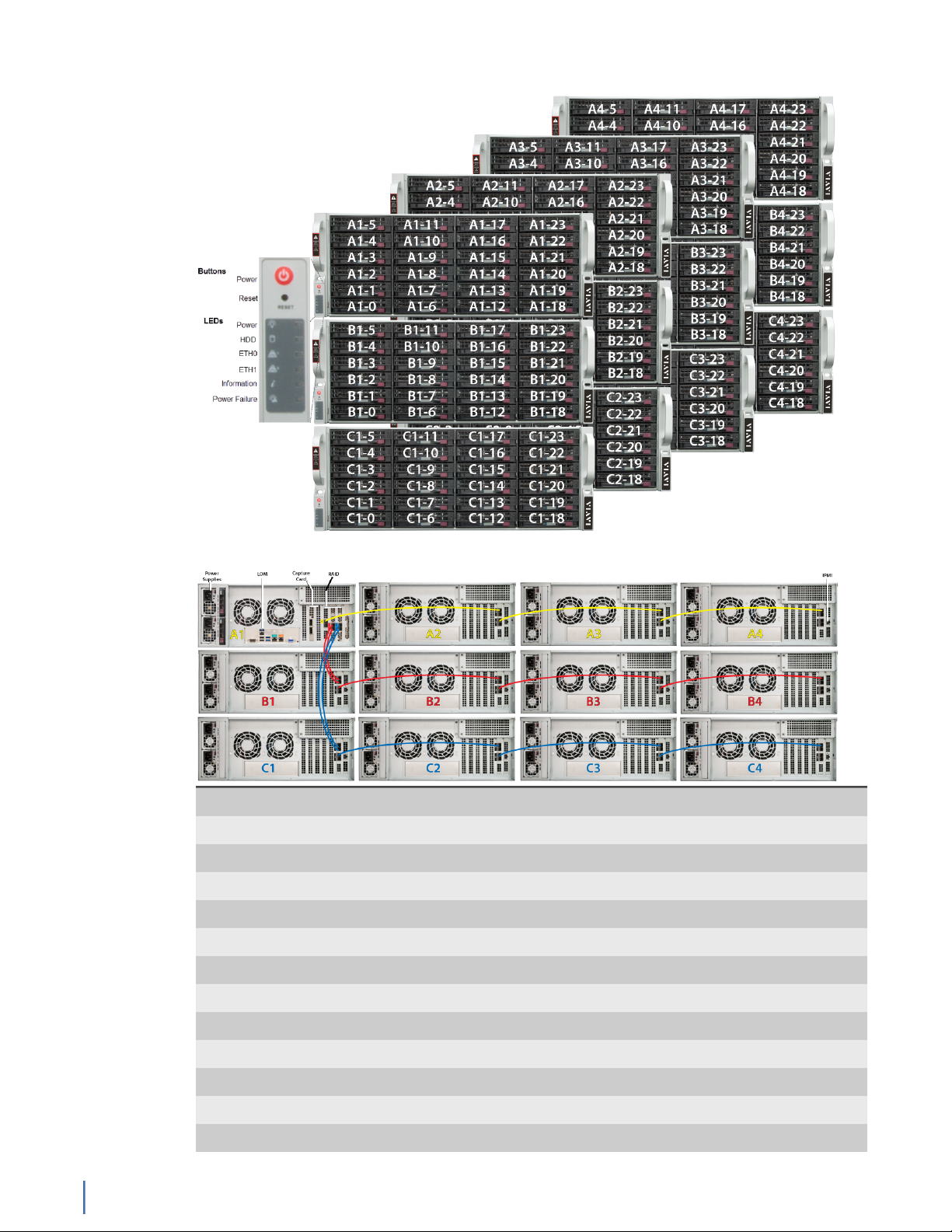
Figure 1: G3-GS-2P40-1152T Front
Figure 2: G3-GS-2P40-1152T Rear
System -
Deployment 40 Gb data center
Base storage 1.2 PB
Max storage 1.2 PB
Lights Out Management (LOM) Yes
Redundant OS drive Yes
OS drive hot swappable Yes
OS drive size 1 TB
RAID drive hot swappable Yes
RAID version 50
Rail kit Yes
Operating system Windows 2012 R2
Physical -
G3-GS-2P40-1152T
12 GigaStor (23 Feb 2018) — Archive/Non-authoritative version
Page 13

Height 60U (12 x 5U)
Width 19 in
Depth 26 in
Weight (mounted)
1
1216 lbs
Weight (handling) 1276.6 lbs
Media -
Monitoring interfaces 2
Speed 40 Gb
Accepted transceivers
2
QSFP+
Performance -
Aggregate performance 40 Gbps
Power -
Redundant power supply Yes
Input frequency 50/60Hz
Input voltage 100V-240V Auto Select
Operational current (amps) 35.9A
Parts list
BTU 10960 BTU/hr
Operational voltage 120V
Power dissipation (watts) 4252W
Relative humidity (non-condensing) 5%-85%
Temperature (operating) 50°F - 95°F / 10°C - 35°C
Temperature (storage) -4°F - 149°F / -20°C - 65°C
1. If applicable, mounted weight includes any rail kits.
2. SFP may be any of Copper 10/100/1000, 1Gb SX/LX. SFP+ may be any of 10Gb SR/LR. QSPF+ may
be any 40Gb SR/LR/BiDi/Universal.
Each appliance comes packed in a number of boxes. The boxes contain the
various components necessary for a successful installation.
The boxes are not numbered as listed here. The numbers merely represent how
many boxes you should expect and what is contained in each one.
♦ Box 1
● 1 Head unit with RAID drives preinstalled
● 1 Rail kit
● 2 Power supply cables
● 2 Ethernet cables
● 1 Product Activation Information envelope containing the product
license
● 1 Quick Start Guide
● 1 Label listing serial numbers of all JBODs for this system. This label
appears on top of the head unit and was attached to the outside of
G3-GS-2P40-1152T
Chapter 1: Appliance installation 13
Page 14
the head unit’s box. Use this label to sort and connect the proper
JBODs to the head unit.
● SFP transceivers (if ordered)
♦ For each JBOD (11) a box that contains:
● 1 JBOD Unit with RAID drives preinstalled
● 1 Rail Kit
● 2 Power supply cables
● Mini-SAS cable(s)
Before installing, ensure you received all of the parts required for your system.
G3-GS-2P40-1152T installation
Getting your appliance installed is the first step to greater visibility of your
network. This topic covers installing your appliance in the cabinet and connecting
it to your network.
Caution: Do not attempt in-cabinet repairs of your appliance. The
appliance is very heavy! Always use a server lift or work with a partner
to install or remove the appliance from the cabinet to perform any
maintenance.
1. Take the appliance and all other components out of the packing materials.
2. Attach the official rail kits (page 73) to your server rack or cabinet.
3. Install the head unit (A1) into your server rack or cabinet. Use a server lift if
necessary. Do not remove the RAID drives from the chassis.
4. Install the JBOD unit(s) into your cabinet. Use a server lift if necessary. Do not
remove the RAID drives from the chassis.
5. Using the SAS cables, connect the RAID ports from the JBOD unit(s) to the
head unit and to other JBOD unit(s).
Figure 3: G3-GS-2P40-1152T Rear
6. Using an Ethernet cable, connect the ETH0 port to the network.
Connecting the ETH0 port allows you to use Windows Remote Desktop or
other tools to control or configure Windows or Windows applications, such as
Observer Analyzer.
7. (Optional) Connect an Ethernet cable from your router or switch to the LOM
or IPMI port.
(Optional) A Lights Out Management or IPMI port provides you a dedicated
management channel for device maintenance. It allows you to monitor,
G3-GS-2P40-1152T
14 GigaStor (23 Feb 2018) — Archive/Non-authoritative version
Page 15
start, stop, and manage your appliance remotely regardless of whether the
appliance is powered on.
8.
Install SFP transceivers (page 179)1 into the open slots on the back of the
capture card(s).
9. If you are connecting to SPAN/mirror ports of a network switch: connect a
straight-through Ethernet cable from the SPAN/mirror ports on your switch to
the SFP transceivers on the capture card.
10. If you are connecting to a network TAP (sold separately):
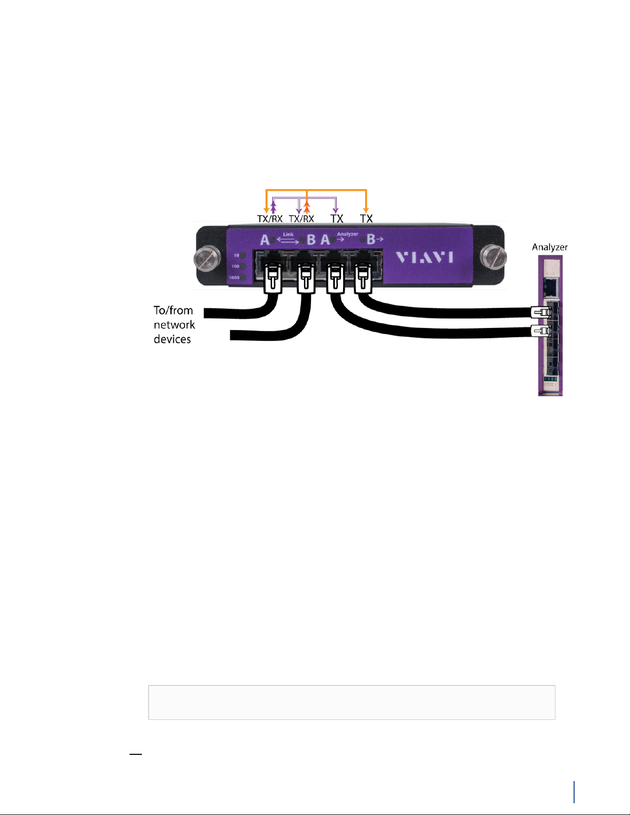
Figure 4: Connecting the TAP to the network device, switch, and analyzer
a. Connect the TX port from your server, firewall, router, or switch to the Link
A port on the TAP.
b. Connect the TX port from your other switch to the Link B port on the TAP.
c. Use two analyzer cables to connect the analyzer port on the TAP to the
SFP transceivers in the capture card.
d. If you have more than one TAP to connect, repeat the process for each TAP.
11. Connect a monitor, keyboard, and mouse to the hardware appliance.
You can use a KVM switch if desired. (The KVM must be compatible with
the operating system used on the appliance.) The user input devices or
KVM switch are only temporarily needed to set the IP address, so you can
disconnect them after the IP address is set.
12. Turn on all JBOD unit(s).
a. Plug the power cords into the rear of the power supplies.
b. Wait until the blue Information LED starts to blink.
c. Use the tip of your finger to press the power button once. The JBOD
control board initiates the power up sequence in three seconds.
See Startup and shutdown (G3-GS models) (page 172).
Caution: The RAID does not properly initialize if the JBOD unit(s) are not
started first. If this happens, restart the head unit.
1.SFP, SFP+, and QSFP+ transceivers are sold separately.
G3-GS-2P40-1152T
Chapter 1: Appliance installation 15
Page 16

13. Turn on the head unit (A1) and wait for the RAID to initialize using the same
procedure as the JBOD.
14. In Windows, change the IP address (page 174) for the ETH0 port (shown as
ETH0 in Network Connections in Windows) using information supplied to
you by your network administrator.
The default IP address (192.168.1.10) is printed on a sticker attached to the
top of the appliance.
15. Ensure the time zone settings match your environment.
16. (Optional) Change the IPMI port (page 176) in the BIOS using a static IP
address provided by your network administrator.
17. (Optional) Change the JBOD IPMI port in the BIOS using a static IP address
provided by your network administrator.
18. Double-click the Observer icon on the Desktop to start Observer.
Your hardware appliance is installed and on your network.
Next, give the ETH0 IP address and IPMI port address, if using, to the Observer
administrator. They need the addresses to add this GigaStor probe to Observer to
capture network traffic with a probe instance.
G3-GS-2P40-576T
The G3-GS-2P40-576T is best suited for 40 Gb data centers.
G3-GS-2P40-576T technical specifications (page 16)
G3-GS-2P40-576T technical specifications
The technical specifications for the product are shown below.
G3-GS-2P40-576T
16 GigaStor (23 Feb 2018) — Archive/Non-authoritative version
Page 17
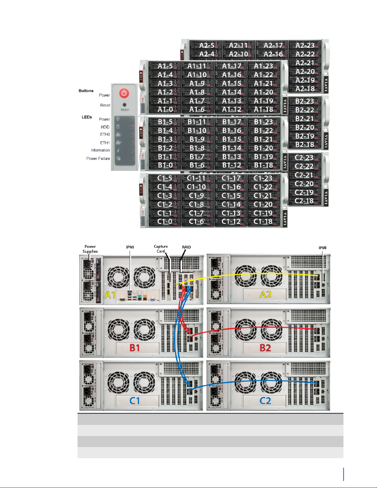
Figure 5: G3-GS-2P40-576T Front
Figure 6: G3-GS-2P40-576T Rear
System -
Deployment 40 Gb data center
Base storage 576 TB
Max storage 1.2 PB
G3-GS-2P40-576T
Chapter 1: Appliance installation 17
Page 18

Lights Out Management (LOM) Yes
Redundant OS drive Yes
OS drive hot swappable Yes
OS drive size 1 TB
RAID drive hot swappable Yes
RAID version 50
Rail kit Yes
Operating system Windows 2012 R2
Physical -
Height 30U (6 x 5U)
Width 19 in
Depth 26 in
Weight (mounted)
1
616 lbs
Weight (handling) 646.6 lbs
Media -
Monitoring interfaces 2
Speed 40 Gb
Accepted transceivers
2
QSFP+
Performance -
Aggregate performance 40 Gbps
Power -
Redundant power supply Yes
Input frequency 50/60Hz
Input voltage 100V-240V Auto Select
Operational current (amps) 19.7A
BTU 7385 BTU/hr
Operational voltage 120V
Power dissipation (watts) 2350W
Relative humidity (non-condensing) 5%-85%
Temperature (operating) 50°F - 95°F / 10°C - 35°C
Temperature (storage) -4°F - 149°F / -20°C - 65°C
1. If applicable, mounted weight includes any rail kits.
2. SFP may be any of Copper 10/100/1000, 1Gb SX/LX. SFP+ may be any of 10Gb SR/LR. QSPF+ may
be any 40Gb SR/LR/BiDi/Universal.
Parts list
Each appliance comes packed in a number of boxes. The boxes contain the
various components necessary for a successful installation.
The boxes are not numbered as listed here. The numbers merely represent how
many boxes you should expect and what is contained in each one.
♦ Box 1
G3-GS-2P40-576T
18 GigaStor (23 Feb 2018) — Archive/Non-authoritative version
Page 19

● 1 Head unit with RAID drives preinstalled
● 1 Rail kit
● 2 Power supply cables
● 2 Ethernet cables
● 1 Product Activation Information envelope containing the product
license
● 1 Quick Start Guide
● 1 Label listing serial numbers of all JBODs for this system. This label
appears on top of the head unit and was attached to the outside of
the head unit’s box. Use this label to sort and connect the proper
JBODs to the head unit.
● SFP transceivers (if ordered)
♦ For each JBOD (5) a box that contains:
● 1 JBOD Unit with RAID drives preinstalled
● 1 Rail Kit
● 2 Power supply cables
● Mini-SAS cable(s)
Before installing, ensure you received all of the parts required for your system.
G3-GS-2P40-576T installation
Getting your appliance installed is the first step to greater visibility of your
network. This topic covers installing your appliance in the cabinet and connecting
it to your network.
Caution: Do not attempt in-cabinet repairs of your appliance. The
appliance is very heavy! Always use a server lift or work with a partner
to install or remove the appliance from the cabinet to perform any
maintenance.
1. Take the appliance and all other components out of the packing materials.
2. Attach the official rail kits (page 73) to your server rack or cabinet.
3. Install the head unit (A1) into your server rack or cabinet. Use a server lift if
necessary. Do not remove the RAID drives from the chassis.
4. Install the JBOD unit(s) into your cabinet. Use a server lift if necessary. Do not
remove the RAID drives from the chassis.
5. Using the SAS cables, connect the RAID ports from the JBOD unit(s) to the
head unit and to other JBOD unit(s).
G3-GS-2P40-576T
Chapter 1: Appliance installation 19
Page 20
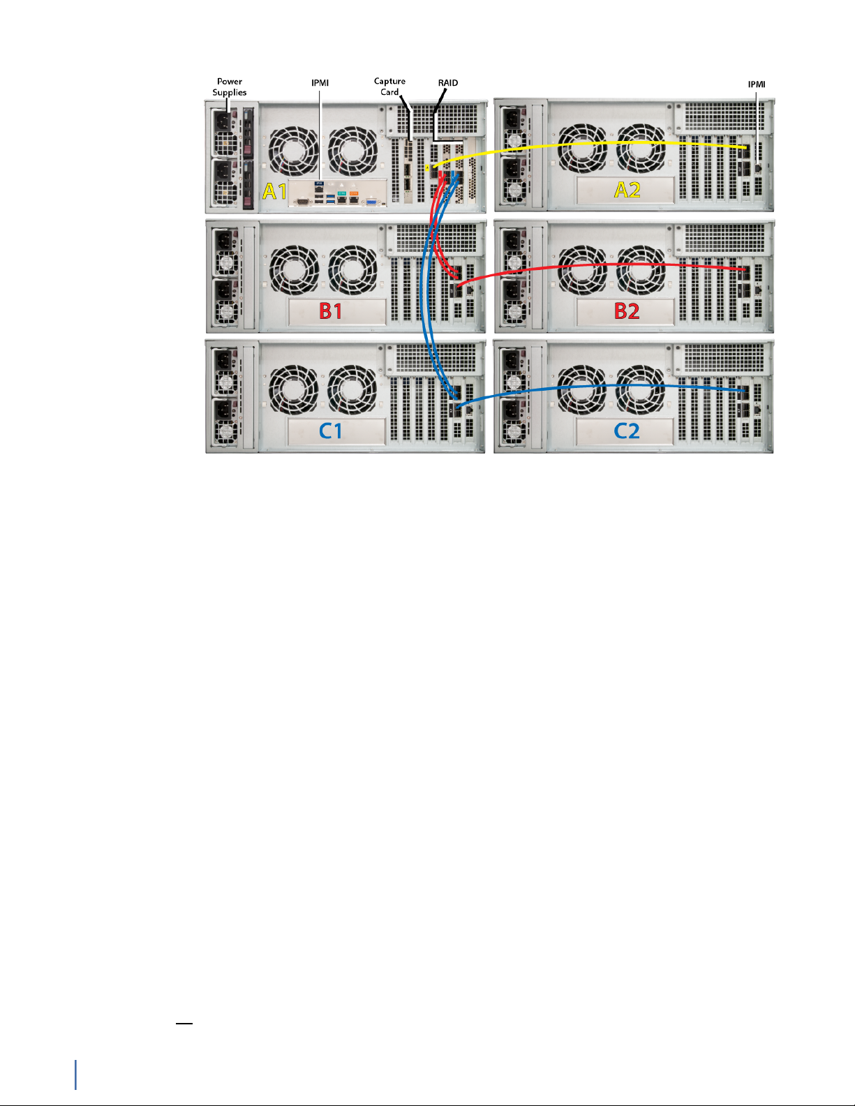
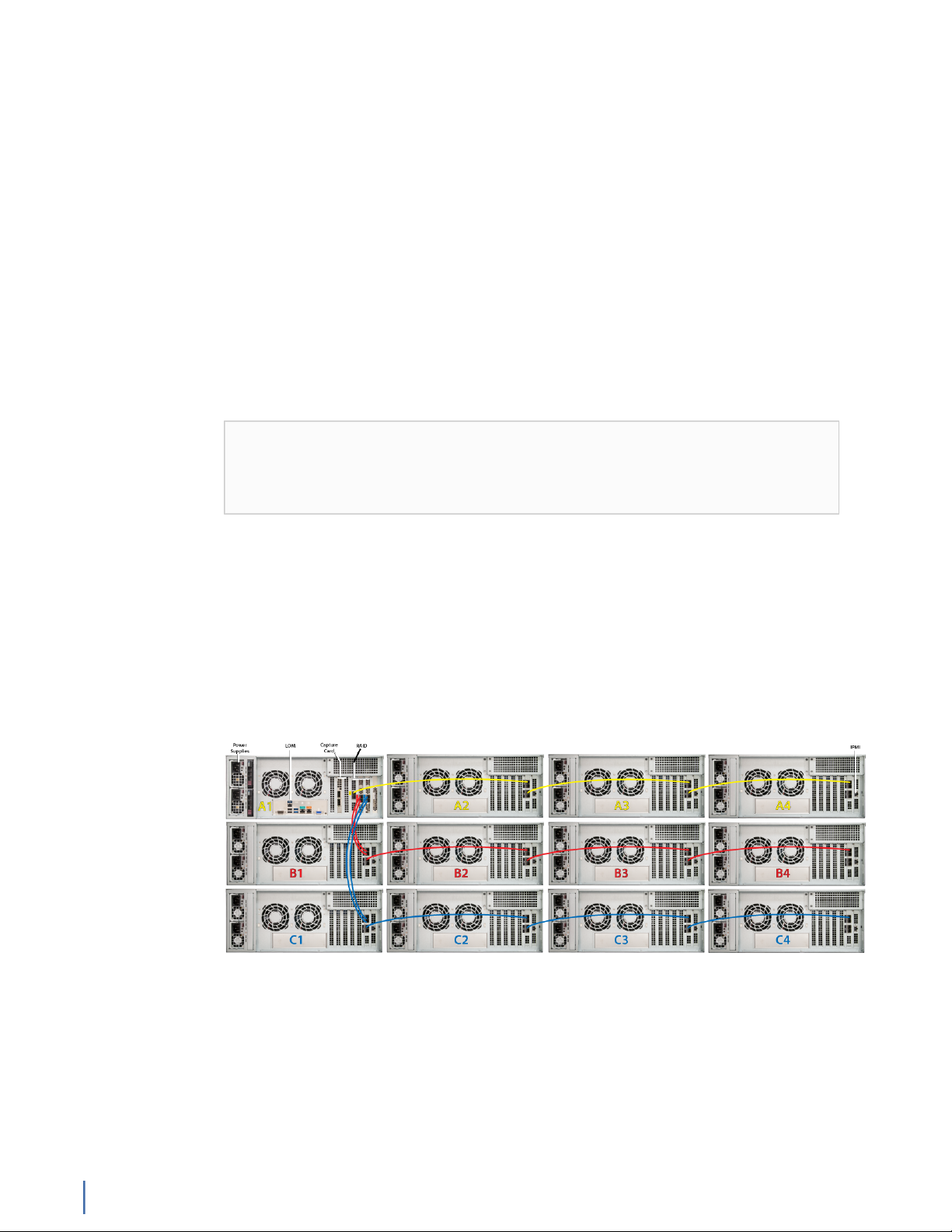
Figure 7: G3-GS-2P40-576T Rear
6. Using an Ethernet cable, connect the ETH0 port to the network.
Connecting the ETH0 port allows you to use Windows Remote Desktop or
other tools to control or configure Windows or Windows applications, such as
Observer.
7. (Optional) Connect an Ethernet cable from your router or switch to the LOM
or IPMI port.
(Optional) A Lights Out Management or IPMI port provides you a dedicated
management channel for device maintenance. It allows you to monitor,
start, stop, and manage your appliance remotely regardless of whether the
appliance is powered on.
8.
Install SFP transceivers (page 179)2 into the open slots on the back of the
capture card(s).
9. If you are connecting to SPAN/mirror ports of a network switch: connect a
straight-through Ethernet cable from the SPAN/mirror ports on your switch to
the SFP transceivers on the capture card.
10. If you are connecting to a network TAP (sold separately):
2.SFP, SFP+, and QSFP+ transceivers are sold separately.
G3-GS-2P40-576T
20 GigaStor (23 Feb 2018) — Archive/Non-authoritative version
Page 21
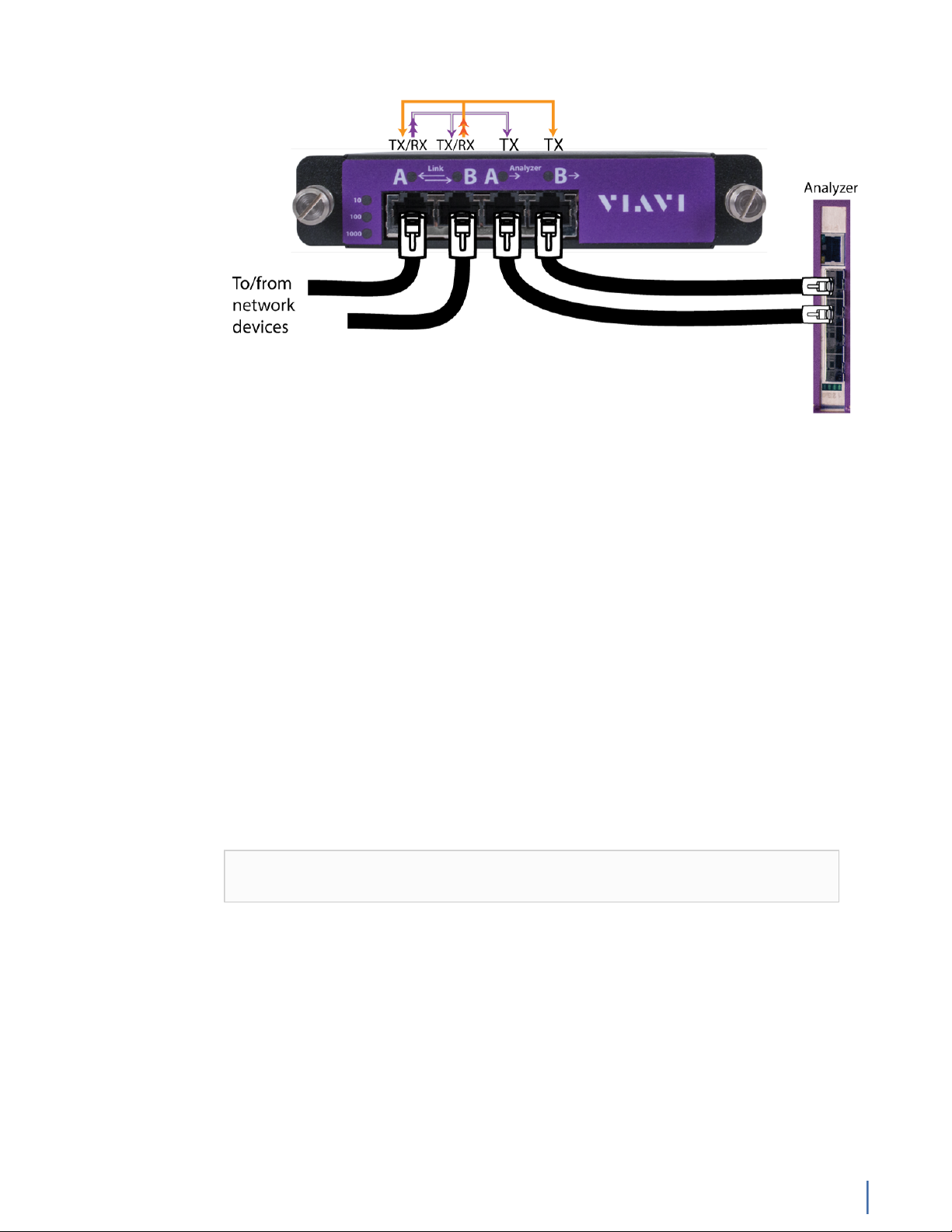
Figure 8: Connecting the TAP to the network device, switch, and analyzer
a. Connect the TX port from your server, firewall, router, or switch to the Link
A port on the TAP.
b. Connect the TX port from your other switch to the Link B port on the TAP.
c. Use two analyzer cables to connect the analyzer port on the TAP to the
SFP transceivers in the capture card.
d. If you have more than one TAP to connect, repeat the process for each TAP.
11. Connect a monitor, keyboard, and mouse to the hardware appliance.
You can use a KVM switch if desired. (The KVM must be compatible with
the operating system used on the appliance.) The user input devices or
KVM switch are only temporarily needed to set the IP address, so you can
disconnect them after the IP address is set.
12. Turn on all JBOD unit(s).
a. Plug the power cords into the rear of the power supplies.
b. Wait until the blue Information LED starts to blink.
c. Use the tip of your finger to press the power button once. The JBOD
control board initiates the power up sequence in three seconds.
See Startup and shutdown (G3-GS models) (page 172).
Caution: The RAID does not properly initialize if the JBOD unit(s) are not
started first. If this happens, restart the head unit.
13. Turn on the head unit (A1) and wait for the RAID to initialize using the same
procedure as the JBOD.
14. In Windows, change the IP address (page 174) for the ETH0 port (shown as
ETH0 in Network Connections in Windows) using information supplied to
you by your network administrator.
The default IP address (192.168.1.10) is printed on a sticker attached to the
top of the appliance.
15. Ensure the time zone settings match your environment.
16. (Optional) Change the IPMI port (page 176) in the BIOS using a static IP
address provided by your network administrator.
G3-GS-2P40-576T
Chapter 1: Appliance installation 21
Page 22
17. (Optional) Change the JBOD IPMI port in the BIOS using a static IP address
provided by your network administrator.
18. Double-click the Observer icon on the Desktop to start Observer.
Your hardware appliance is installed and on your network.
Next, give the ETH0 IP address and IPMI port address, if using, to the Observer
administrator. They need the addresses to add this GigaStor probe to Observer to
capture network traffic with a probe instance.
G3-GS-2P40-288T
The G3-GS-2P40-288T is best suited for 40 Gb data centers.
G3-GS-2P40-288T technical specifications (page 22)
G3-GS-2P40-288T technical specifications
The technical specifications for the product are shown below.
Figure 9: G3-GS-2P40-288T Front
G3-GS-2P40-288T
22 GigaStor (23 Feb 2018) — Archive/Non-authoritative version
Page 23
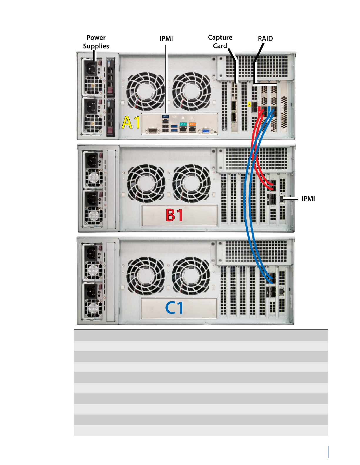
Figure 10: G3-GS-2P40-288T Rear
System -
Deployment 40 Gb data center
Base storage 288 TB
Max storage 1.2 PB
Lights Out Management (LOM) Yes
Redundant OS drive Yes
OS drive hot swappable Yes
OS drive size 1 TB
RAID drive hot swappable Yes
RAID version 5
G3-GS-2P40-288T
Chapter 1: Appliance installation 23
Page 24

Rail kit Yes
Operating system Windows 2012 R2
Physical -
Height 15U (3 x 5U)
Width 19 in
Depth 26 in
Weight (mounted)
1
316 lbs
Weight (handling) 331.6 lbs
Media -
Monitoring interfaces 2
Speed 40 Gb
Accepted transceivers
2
QSFP+
Performance -
Aggregate performance 40 Gbps
Power -
Redundant power supply Yes
Parts list
Input frequency 50/60Hz
Input voltage 100V-240V Auto Select
Operational current (amps) 11.60A
BTU 4395 BTU/hr
Operational voltage 120V
Power dissipation (watts) 1399W
Relative humidity (non-condensing) 5%-85%
Temperature (operating) 50°F - 95°F / 10°C - 35°C
Temperature (storage) -4°F - 149°F / -20°C - 65°C
1. If applicable, mounted weight includes any rail kits.
2. SFP may be any of Copper 10/100/1000, 1Gb SX/LX. SFP+ may be any of 10Gb SR/LR. QSPF+ may
be any 40Gb SR/LR/BiDi/Universal.
Each appliance comes packed in a number of boxes. The boxes contain the
various components necessary for a successful installation.
The boxes are not numbered as listed here. The numbers merely represent how
many boxes you should expect and what is contained in each one.
♦ Box 1
● 1 Head unit with RAID drives preinstalled
● 1 Rail kit
● 2 Power supply cables
● 2 Ethernet cables
● 1 Product Activation Information envelope containing the product
license
G3-GS-2P40-288T
24 GigaStor (23 Feb 2018) — Archive/Non-authoritative version
Page 25
● 1 Quick Start Guide
● 1 Label listing serial numbers of all JBODs for this system. This label
appears on top of the head unit and was attached to the outside of
the head unit’s box. Use this label to sort and connect the proper
JBODs to the head unit.
● SFP transceivers (if ordered)
♦ For each JBOD (2) a box that contains:
● 1 JBOD Unit with RAID drives preinstalled
● 1 Rail Kit
● 2 Power supply cables
● Mini-SAS cable(s)
Before installing, ensure you received all of the parts required for your system.
G3-GS-2P40-288T installation
Getting your appliance installed is the first step to greater visibility of your
network. This topic covers installing your appliance in the cabinet and connecting
it to your network.
Caution: Do not attempt in-cabinet repairs of your appliance. The
appliance is very heavy! Always use a server lift or work with a partner
to install or remove the appliance from the cabinet to perform any
maintenance.
1. Take the appliance and all other components out of the packing materials.
2. Attach the official rail kits (page 73) to your server rack or cabinet.
3. Install the head unit (A1) into your server rack or cabinet. Use a server lift if
necessary. Do not remove the RAID drives from the chassis.
4. Install the JBOD unit(s) into your cabinet. Use a server lift if necessary. Do not
remove the RAID drives from the chassis.
5. Using the SAS cables, connect the RAID ports from the JBOD unit(s) to the
head unit.
G3-GS-2P40-288T
Chapter 1: Appliance installation 25
Page 26
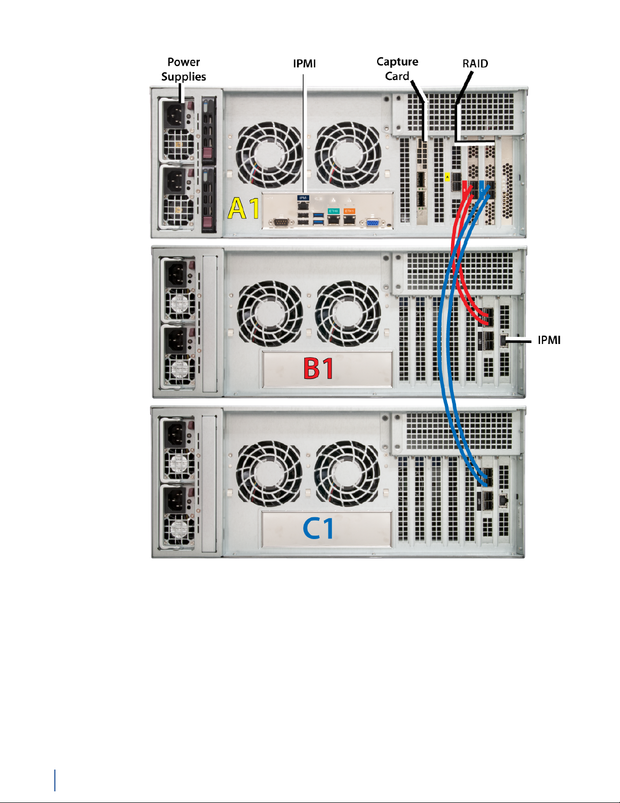
Figure 11: G3-GS-2P40-288T Rear
6. Using an Ethernet cable, connect the ETH0 port to the network.
Connecting the ETH0 port allows you to use Windows Remote Desktop or
other tools to control or configure Windows or Windows applications, such as
Observer.
7. (Optional) Connect an Ethernet cable from your router or switch to the LOM
or IPMI port.
(Optional) A Lights Out Management or IPMI port provides you a dedicated
management channel for device maintenance. It allows you to monitor,
start, stop, and manage your appliance remotely regardless of whether the
appliance is powered on.
G3-GS-2P40-288T
26 GigaStor (23 Feb 2018) — Archive/Non-authoritative version
Page 27

8.
Install SFP transceivers (page 179)3 into the open slots on the back of the
capture card(s).
9. If you are connecting to SPAN/mirror ports of a network switch: connect a
straight-through Ethernet cable from the SPAN/mirror ports on your switch to
the SFP transceivers on the capture card.
10. If you are connecting to a network TAP (sold separately):
Figure 12: Connecting the TAP to the network device, switch, and analyzer
a. Connect the TX port from your server, firewall, router, or switch to the Link
A port on the TAP.
b. Connect the TX port from your other switch to the Link B port on the TAP.
c. Use two analyzer cables to connect the analyzer port on the TAP to the
SFP transceivers in the capture card.
d. If you have more than one TAP to connect, repeat the process for each TAP.
11. Connect a monitor, keyboard, and mouse to the hardware appliance.
You can use a KVM switch if desired. (The KVM must be compatible with
the operating system used on the appliance.) The user input devices or
KVM switch are only temporarily needed to set the IP address, so you can
disconnect them after the IP address is set.
12. Turn on all JBOD unit(s).
a. Plug the power cords into the rear of the power supplies.
b. Wait until the blue Information LED starts to blink.
c. Use the tip of your finger to press the power button once. The JBOD
control board initiates the power up sequence in three seconds.
See Startup and shutdown (G3-GS models) (page 172).
Caution: The RAID does not properly initialize if the JBOD unit(s) are not
started first. If this happens, restart the head unit.
13. Turn on the head unit (A1) and wait for the RAID to initialize using the same
procedure as the JBOD.
3.SFP, SFP+, and QSFP+ transceivers are sold separately.
G3-GS-2P40-288T
Chapter 1: Appliance installation 27
Page 28
14. In Windows, change the IP address (page 174) for the ETH0 port (shown as
ETH0 in Network Connections in Windows) using information supplied to
you by your network administrator.
The default IP address (192.168.1.10) is printed on a sticker attached to the
top of the appliance.
15. Ensure the time zone settings match your environment.
16. (Optional) Change the IPMI port (page 176) in the BIOS using a static IP
address provided by your network administrator.
17. (Optional) Change the JBOD IPMI port in the BIOS using a static IP address
provided by your network administrator.
18. Double-click the Observer icon on the Desktop to start Observer.
Your hardware appliance is installed and on your network.
Next, give the ETH0 IP address and IPMI port address, if using, to the Observer
administrator. They need the addresses to add this GigaStor probe to Observer to
capture network traffic with a probe instance.
G3-GS-8P-1152T
The G3-GS-8P-1152T is best suited for 40 Gb data centers.
G3-GS-8P-1152T technical specifications (page 28)
G3-GS-8P-1152T technical specifications
The technical specifications for the product are shown below.
Figure 13: G3-GS-8P-1152T Front
G3-GS-8P-1152T
28 GigaStor (23 Feb 2018) — Archive/Non-authoritative version
Page 29
Figure 14: G3-GS-8P-1152T Rear
System -
Deployment 40 Gb data center
Base storage 1.2 PB
Max storage 1.2 PB
Lights Out Management (LOM) Yes
Redundant OS drive Yes
OS drive hot swappable Yes
OS drive size 1 TB
RAID drive hot swappable Yes
RAID version 50
Rail kit Yes
Operating system Windows 2012 R2
Physical -
Height 48U (12 x 4U)
Width 19 in
Depth 26 in
Weight (mounted)
1
1216 lbs
Weight (handling) 1276.6 lbs
Media -
Monitoring interfaces 8
Speed 1/10 Gb
Accepted transceivers
2
SFP/SFP+
Performance -
Aggregate performance 40 Gbps
Power -
Redundant power supply Yes
Input frequency 50/60Hz
Input voltage 100V-240V Auto Select
Operational current (amps) 35.9A
BTU 10960 BTU/hr
Chapter 1: Appliance installation 29
G3-GS-8P-1152T
Page 30

Parts list
Operational voltage 120V
Power dissipation (watts) 4252W
Relative humidity (non-condensing) 5%-85%
Temperature (operating) 50°F - 95°F / 10°C - 35°C
Temperature (storage) -4°F - 149°F / -20°C - 65°C
1. If applicable, mounted weight includes any rail kits.
2. SFP may be any of Copper 10/100/1000, 1Gb SX/LX. SFP+ may be any of 10Gb SR/LR. QSPF+ may
be any 40Gb SR/LR/BiDi/Universal.
Each appliance comes packed in a number of boxes. The boxes contain the
various components necessary for a successful installation.
The boxes are not numbered as listed here. The numbers merely represent how
many boxes you should expect and what is contained in each one.
♦ Box 1
● 1 Head unit with RAID drives preinstalled
● 1 Rail kit
● 2 Power supply cables
● 2 Ethernet cables
● 1 Product Activation Information envelope containing the product
license
● 1 Quick Start Guide
● 1 Label listing serial numbers of all JBODs for this system. This label
appears on top of the head unit and was attached to the outside of
the head unit’s box. Use this label to sort and connect the proper
JBODs to the head unit.
● SFP transceivers (if ordered)
♦ For each JBOD (11) a box that contains:
● 1 JBOD Unit with RAID drives preinstalled
● 1 Rail Kit
● 2 Power supply cables
● Mini-SAS cable(s)
Before installing, ensure you received all of the parts required for your system.
G3-GS-8P-1152T installation
Getting your appliance installed is the first step to greater visibility of your
network. This topic covers installing your appliance in the cabinet and connecting
it to your network.
Caution: Do not attempt in-cabinet repairs of your appliance. The
appliance is very heavy! Always use a server lift or work with a partner
to install or remove the appliance from the cabinet to perform any
maintenance.
1. Take the appliance and all other components out of the packing materials.
G3-GS-8P-1152T
30 GigaStor (23 Feb 2018) — Archive/Non-authoritative version
Page 31

2. Attach the official rail kits (page 73) to your server rack or cabinet.
3. Install the head unit (A1) into your server rack or cabinet. Use a server lift if
necessary. Do not remove the RAID drives from the chassis.
4. Install the JBOD unit(s) into your cabinet. Use a server lift if necessary. Do not
remove the RAID drives from the chassis.
5. Using the SAS cables, connect the RAID ports from the JBOD unit(s) to the
head unit and to other JBOD unit(s).
Figure 15: G3-GS-8P-1152T Rear
6. Using an Ethernet cable, connect the ETH0 port to the network.
Connecting the ETH0 port allows you to use Windows Remote Desktop or
other tools to control or configure Windows or Windows applications, such as
Observer.
7. (Optional) Connect an Ethernet cable from your router or switch to the LOM
or IPMI port.
(Optional) A Lights Out Management or IPMI port provides you a dedicated
management channel for device maintenance. It allows you to monitor,
start, stop, and manage your appliance remotely regardless of whether the
appliance is powered on.
8.
Install SFP transceivers (page 179)4 into the open slots on the back of the
capture card(s).
9. If you are connecting to SPAN/mirror ports of a network switch: connect a
straight-through Ethernet cable from the SPAN/mirror ports on your switch to
the SFP transceivers on the capture card.
10. If you are connecting to a network TAP (sold separately):
4.SFP, SFP+, and QSFP+ transceivers are sold separately.
G3-GS-8P-1152T
Chapter 1: Appliance installation 31
Page 32

Figure 16: Connecting the TAP to the network device, switch, and analyzer
a. Connect the TX port from your server, firewall, router, or switch to the Link
A port on the TAP.
b. Connect the TX port from your other switch to the Link B port on the TAP.
c. Use two analyzer cables to connect the analyzer port on the TAP to the
SFP transceivers in the capture card.
d. If you have more than one TAP to connect, repeat the process for each TAP.
11. Connect a monitor, keyboard, and mouse to the hardware appliance.
You can use a KVM switch if desired. (The KVM must be compatible with
the operating system used on the appliance.) The user input devices or
KVM switch are only temporarily needed to set the IP address, so you can
disconnect them after the IP address is set.
12. Turn on all JBOD unit(s).
a. Plug the power cords into the rear of the power supplies.
b. Wait until the blue Information LED starts to blink.
c. Use the tip of your finger to press the power button once. The JBOD
control board initiates the power up sequence in three seconds.
See Startup and shutdown (G3-GS models) (page 172).
Caution: The RAID does not properly initialize if the JBOD unit(s) are not
started first. If this happens, restart the head unit.
13. Turn on the head unit (A1) and wait for the RAID to initialize using the same
procedure as the JBOD.
14. In Windows, change the IP address (page 174) for the ETH0 port (shown as
ETH0 in Network Connections in Windows) using information supplied to
you by your network administrator.
The default IP address (192.168.1.10) is printed on a sticker attached to the
top of the appliance.
15. Ensure the time zone settings match your environment.
16. (Optional) Change the IPMI port (page 176) in the BIOS using a static IP
address provided by your network administrator.
G3-GS-8P-1152T
32 GigaStor (23 Feb 2018) — Archive/Non-authoritative version
Page 33

17. (Optional) Change the JBOD IPMI port in the BIOS using a static IP address
provided by your network administrator.
18. Double-click the Observer icon on the Desktop to start Observer.
Your hardware appliance is installed and on your network.
Next, give the ETH0 IP address and IPMI port address, if using, to the Observer
administrator. They need the addresses to add this GigaStor probe to Observer to
capture network traffic with a probe instance.
G3-GS-8P-768T
The G3-GS-8P-768T is best suited for 40 Gb data centers.
G3-GS-8P-768T technical specifications (page 33)
G3-GS-8P-768T technical specifications
The technical specifications for the product are shown below.
Figure 17: G3-GS-8P-768T Front
Figure 18: G3-GS-8P-768T Rear
System -
Deployment Multi-10 Gb data center
Base storage 768 TB
Max storage 768 TB
Lights Out Management (LOM) Yes
Redundant OS drive Yes
Chapter 1: Appliance installation 33
G3-GS-8P-768T
Page 34

OS drive hot swappable Yes
OS drive size 1 TB
RAID drive hot swappable Yes
RAID version 50
Rail kit Yes
Operating system Windows 2012 R2
Physical -
Height 32U (8 x 4U)
Width 19 in
Depth 26 in
Weight (mounted)
1
816 lbs
Weight (handling) 856.6 lbs
Media -
Monitoring interfaces 8
Speed 1/10 Gb
Accepted transceivers
2
SFP/SFP+
Parts list
Performance -
Aggregate performance 40 Gbps
Power -
Redundant power supply Yes
Input frequency 50/60Hz
Input voltage 100V-240V Auto Select
Operational current (amps) 25.1A
BTU 9377 BTU/hr
Operational voltage 120V
Power dissipation (watts) 2985W
Relative humidity (non-condensing) 5%-85%
Temperature (operating) 50°F - 95°F / 10°C - 35°C
Temperature (storage) -4°F - 149°F / -20°C - 65°C
1. If applicable, mounted weight includes any rail kits.
2. SFP may be any of Copper 10/100/1000, 1Gb SX/LX. SFP+ may be any of 10Gb SR/LR. QSPF+ may
be any 40Gb SR/LR/BiDi/Universal.
Each appliance comes packed in a number of boxes. The boxes contain the
various components necessary for a successful installation.
The boxes are not numbered as listed here. The numbers merely represent how
many boxes you should expect and what is contained in each one.
♦ Box 1
● 1 Head unit with RAID drives preinstalled
● 1 Rail kit
G3-GS-8P-768T
34 GigaStor (23 Feb 2018) — Archive/Non-authoritative version
Page 35

● 2 Power supply cables
● 2 Ethernet cables
● 1 Product Activation Information envelope containing the product
license
● 1 Quick Start Guide
● 1 Label listing serial numbers of all JBODs for this system. This label
appears on top of the head unit and was attached to the outside of
the head unit’s box. Use this label to sort and connect the proper
JBODs to the head unit.
● SFP transceivers (if ordered)
♦ For each JBOD (7) a box that contains:
● 1 JBOD Unit with RAID drives preinstalled
● 1 Rail Kit
● 2 Power supply cables
● Mini-SAS cable(s)
Before installing, ensure you received all of the parts required for your system.
G3-GS-8P-768T installation
Getting your appliance installed is the first step to greater visibility of your
network. This topic covers installing your appliance in the cabinet and connecting
it to your network.
Caution: Do not attempt in-cabinet repairs of your appliance. The
appliance is very heavy! Always use a server lift or work with a partner
to install or remove the appliance from the cabinet to perform any
maintenance.
1. Take the appliance and all other components out of the packing materials.
2. Attach the official rail kits (page 73) to your server rack or cabinet.
3. Install the head unit (A1) into your server rack or cabinet. Use a server lift if
necessary. Do not remove the RAID drives from the chassis.
4. Install the JBOD unit(s) into your cabinet. Use a server lift if necessary. Do not
remove the RAID drives from the chassis.
5. Using the SAS cables, connect the RAID ports from the JBOD unit(s) to the
head unit and to other JBOD unit(s).
Figure 19: G3-GS-8P-768T Rear
6. Using an Ethernet cable, connect the ETH0 port to the network.
Connecting the ETH0 port allows you to use Windows Remote Desktop or
other tools to control or configure Windows or Windows applications, such as
Observer.
G3-GS-8P-768T
Chapter 1: Appliance installation 35
Page 36

7. (Optional) Connect an Ethernet cable from your router or switch to the LOM
or IPMI port.
(Optional) A Lights Out Management or IPMI port provides you a dedicated
management channel for device maintenance. It allows you to monitor,
start, stop, and manage your appliance remotely regardless of whether the
appliance is powered on.
8.
Install SFP transceivers (page 179)5 into the open slots on the back of the
capture card(s).
9. If you are connecting to SPAN/mirror ports of a network switch: connect a
straight-through Ethernet cable from the SPAN/mirror ports on your switch to
the SFP transceivers on the capture card.
10. If you are connecting to a network TAP (sold separately):
Figure 20: Connecting the TAP to the network device, switch, and analyzer
a. Connect the TX port from your server, firewall, router, or switch to the Link
A port on the TAP.
b. Connect the TX port from your other switch to the Link B port on the TAP.
c. Use two analyzer cables to connect the analyzer port on the TAP to the
SFP transceivers in the capture card.
d. If you have more than one TAP to connect, repeat the process for each TAP.
11. Connect a monitor, keyboard, and mouse to the hardware appliance.
You can use a KVM switch if desired. (The KVM must be compatible with
the operating system used on the appliance.) The user input devices or
KVM switch are only temporarily needed to set the IP address, so you can
disconnect them after the IP address is set.
12. Turn on all JBOD unit(s).
a. Plug the power cords into the rear of the power supplies.
b. Wait until the blue Information LED starts to blink.
c. Use the tip of your finger to press the power button once. The JBOD
control board initiates the power up sequence in three seconds.
See Startup and shutdown (G3-GS models) (page 172).
5.SFP, SFP+, and QSFP+ transceivers are sold separately.
G3-GS-8P-768T
36 GigaStor (23 Feb 2018) — Archive/Non-authoritative version
Page 37

Caution: The RAID does not properly initialize if the JBOD unit(s) are not
started first. If this happens, restart the head unit.
13. Turn on the head unit (A1) and wait for the RAID to initialize using the same
procedure as the JBOD.
14. In Windows, change the IP address (page 174) for the ETH0 port (shown as
ETH0 in Network Connections in Windows) using information supplied to
you by your network administrator.
The default IP address (192.168.1.10) is printed on a sticker attached to the
top of the appliance.
15. Ensure the time zone settings match your environment.
16. (Optional) Change the IPMI port (page 176) in the BIOS using a static IP
address provided by your network administrator.
17. (Optional) Change the JBOD IPMI port in the BIOS using a static IP address
provided by your network administrator.
18. Double-click the Observer icon on the Desktop to start Observer.
Your hardware appliance is installed and on your network.
Next, give the ETH0 IP address and IPMI port address, if using, to the Observer
administrator. They need the addresses to add this GigaStor probe to Observer to
capture network traffic with a probe instance.
G3-GS-8P-576T
The G3-GS-8P-576T is best suited for 40 Gb data centers.
G3-GS-8P-576T technical specifications (page 37)
G3-GS-8P-576T technical specifications
The technical specifications for the product are shown below.
G3-GS-8P-576T
Chapter 1: Appliance installation 37
Page 38

Figure 21: G3-GS-8P-576T Front
Figure 22: G3-GS-8P-576T Rear
System -
Deployment 40 Gb data center
Base storage 576 TB
Max storage 1.2 PB
G3-GS-8P-576T
38 GigaStor (23 Feb 2018) — Archive/Non-authoritative version
Page 39

Lights Out Management (LOM) Yes
Redundant OS drive Yes
OS drive hot swappable Yes
OS drive size 1 TB
RAID drive hot swappable Yes
RAID version 50
Rail kit Yes
Operating system Windows 2012 R2
Physical -
Height 30U (6 x 5U)
Width 19 in
Depth 26 in
Weight (mounted)
1
616 lbs
Weight (handling) 646.6 lbs
Media -
Monitoring interfaces 8
Speed 1/10 Gb
Accepted transceivers
2
SFP/SFP+
Performance -
Aggregate performance 40 Gbps
Power -
Redundant power supply Yes
Input frequency 50/60Hz
Input voltage 100V-240V Auto Select
Operational current (amps) 19.7A
BTU 7385 BTU/hr
Operational voltage 120V
Power dissipation (watts) 2350W
Relative humidity (non-condensing) 5%-85%
Temperature (operating) 50°F - 95°F / 10°C - 35°C
Temperature (storage) -4°F - 149°F / -20°C - 65°C
1. If applicable, mounted weight includes any rail kits.
2. SFP may be any of Copper 10/100/1000, 1Gb SX/LX. SFP+ may be any of 10Gb SR/LR. QSPF+ may
be any 40Gb SR/LR/BiDi/Universal.
Parts list
Each appliance comes packed in a number of boxes. The boxes contain the
various components necessary for a successful installation.
The boxes are not numbered as listed here. The numbers merely represent how
many boxes you should expect and what is contained in each one.
♦ Box 1
G3-GS-8P-576T
Chapter 1: Appliance installation 39
Page 40

● 1 Head unit with RAID drives preinstalled
● 1 Rail kit
● 2 Power supply cables
● 2 Ethernet cables
● 1 Product Activation Information envelope containing the product
license
● 1 Quick Start Guide
● 1 Label listing serial numbers of all JBODs for this system. This label
appears on top of the head unit and was attached to the outside of
the head unit’s box. Use this label to sort and connect the proper
JBODs to the head unit.
● SFP transceivers (if ordered)
♦ For each JBOD (5) a box that contains:
● 1 JBOD Unit with RAID drives preinstalled
● 1 Rail Kit
● 2 Power supply cables
● Mini-SAS cable(s)
Before installing, ensure you received all of the parts required for your system.
G3-GS-8P-576T installation
Getting your appliance installed is the first step to greater visibility of your
network. This topic covers installing your appliance in the cabinet and connecting
it to your network.
Caution: Do not attempt in-cabinet repairs of your appliance. The
appliance is very heavy! Always use a server lift or work with a partner
to install or remove the appliance from the cabinet to perform any
maintenance.
1. Take the appliance and all other components out of the packing materials.
2. Attach the official rail kits (page 73) to your server rack or cabinet.
3. Install the head unit (A1) into your server rack or cabinet. Use a server lift if
necessary. Do not remove the RAID drives from the chassis.
4. Install the JBOD unit(s) into your cabinet. Use a server lift if necessary. Do not
remove the RAID drives from the chassis.
5. Using the SAS cables, connect the RAID ports from the JBOD unit(s) to the
head unit and to other JBOD unit(s).
G3-GS-8P-576T
40 GigaStor (23 Feb 2018) — Archive/Non-authoritative version
Page 41

Figure 23: G3-GS-8P-576T Rear
6. Using an Ethernet cable, connect the ETH0 port to the network.
Connecting the ETH0 port allows you to use Windows Remote Desktop or
other tools to control or configure Windows or Windows applications, such as
Observer.
7. (Optional) Connect an Ethernet cable from your router or switch to the LOM
or IPMI port.
(Optional) A Lights Out Management or IPMI port provides you a dedicated
management channel for device maintenance. It allows you to monitor,
start, stop, and manage your appliance remotely regardless of whether the
appliance is powered on.
8.
Install SFP transceivers (page 179)6 into the open slots on the back of the
capture card(s).
9. If you are connecting to SPAN/mirror ports of a network switch: connect a
straight-through Ethernet cable from the SPAN/mirror ports on your switch to
the SFP transceivers on the capture card.
10. If you are connecting to a network TAP (sold separately):
6.SFP, SFP+, and QSFP+ transceivers are sold separately.
G3-GS-8P-576T
Chapter 1: Appliance installation 41
Page 42

Figure 24: Connecting the TAP to the network device, switch, and analyzer
a. Connect the TX port from your server, firewall, router, or switch to the Link
A port on the TAP.
b. Connect the TX port from your other switch to the Link B port on the TAP.
c. Use two analyzer cables to connect the analyzer port on the TAP to the
SFP transceivers in the capture card.
d. If you have more than one TAP to connect, repeat the process for each TAP.
11. Connect a monitor, keyboard, and mouse to the hardware appliance.
You can use a KVM switch if desired. (The KVM must be compatible with
the operating system used on the appliance.) The user input devices or
KVM switch are only temporarily needed to set the IP address, so you can
disconnect them after the IP address is set.
12. Turn on all JBOD unit(s).
a. Plug the power cords into the rear of the power supplies.
b. Wait until the blue Information LED starts to blink.
c. Use the tip of your finger to press the power button once. The JBOD
control board initiates the power up sequence in three seconds.
See Startup and shutdown (G3-GS models) (page 172).
Caution: The RAID does not properly initialize if the JBOD unit(s) are not
started first. If this happens, restart the head unit.
13. Turn on the head unit (A1) and wait for the RAID to initialize using the same
procedure as the JBOD.
14. In Windows, change the IP address (page 174) for the ETH0 port (shown as
ETH0 in Network Connections in Windows) using information supplied to
you by your network administrator.
The default IP address (192.168.1.10) is printed on a sticker attached to the
top of the appliance.
15. Ensure the time zone settings match your environment.
16. (Optional) Change the IPMI port (page 176) in the BIOS using a static IP
address provided by your network administrator.
G3-GS-8P-576T
42 GigaStor (23 Feb 2018) — Archive/Non-authoritative version
Page 43

17. (Optional) Change the JBOD IPMI port in the BIOS using a static IP address
provided by your network administrator.
18. Double-click the Observer icon on the Desktop to start Observer.
Your hardware appliance is installed and on your network.
Next, give the ETH0 IP address and IPMI port address, if using, to the Observer
administrator. They need the addresses to add this GigaStor probe to Observer to
capture network traffic with a probe instance.
G3-GS-8P-384T
The G3-GS-8P-384T is best suited for 40 Gb data centers.
G3-GS-8P-384T technical specifications (page 43)
G3-GS-8P-384T technical specifications
The technical specifications for the product are shown below.
Figure 25: G3-GS-8P-384T Front
Figure 26: G3-GS-8P-384T Rear
G3-GS-8P-384T
Chapter 1: Appliance installation 43
Page 44

System -
Deployment Multi-10 Gb data center
Base storage 384 TB
Max storage 768 TB
Lights Out Management (LOM) Yes
Redundant OS drive Yes
OS drive hot swappable Yes
OS drive size 1 TB
RAID drive hot swappable Yes
RAID version 50
Rail kit Yes
Operating system Windows 2012 R2
Physical -
Height 16U (4 x 4U)
Width 19 in
Depth 26 in
Weight (mounted)
1
416 lbs
Weight (handling) 436.6 lbs
Media -
Monitoring interfaces 8
Speed 1/10 Gb
Accepted transceivers
2
SFP/SFP+
Performance -
Aggregate performance 40 Gbps
Power -
Redundant power supply Yes
Input frequency 50/60Hz
Input voltage 100V-240V Auto Select
Operational current (amps) 14.3A
BTU 5391 BTU/hr
Operational voltage 120V
Power dissipation (watts) 1716W
Relative humidity (non-condensing) 5%-85%
Temperature (operating) 50°F - 95°F / 10°C - 35°C
Temperature (storage) -4°F - 149°F / -20°C - 65°C
1. If applicable, mounted weight includes any rail kits.
2. SFP may be any of Copper 10/100/1000, 1Gb SX/LX. SFP+ may be any of 10Gb SR/LR. QSPF+ may
be any 40Gb SR/LR/BiDi/Universal.
G3-GS-8P-384T
44 GigaStor (23 Feb 2018) — Archive/Non-authoritative version
Page 45

Parts list
Each appliance comes packed in a number of boxes. The boxes contain the
various components necessary for a successful installation.
The boxes are not numbered as listed here. The numbers merely represent how
many boxes you should expect and what is contained in each one.
♦ Box 1
● 1 Head unit with RAID drives preinstalled
● 1 Rail kit
● 2 Power supply cables
● 2 Ethernet cables
● 1 Product Activation Information envelope containing the product
license
● 1 Quick Start Guide
● 1 Label listing serial numbers of all JBODs for this system. This label
appears on top of the head unit and was attached to the outside of
the head unit’s box. Use this label to sort and connect the proper
JBODs to the head unit.
● SFP transceivers (if ordered)
♦ For each JBOD (3) a box that contains:
● 1 JBOD Unit with RAID drives preinstalled
● 1 Rail Kit
● 2 Power supply cables
● Mini-SAS cable(s)
Before installing, ensure you received all of the parts required for your system.
G3-GS-8P-384T installation
Getting your appliance installed is the first step to greater visibility of your
network. This topic covers installing your appliance in the cabinet and connecting
it to your network.
Caution: Do not attempt in-cabinet repairs of your appliance. The
appliance is very heavy! Always use a server lift or work with a partner
to install or remove the appliance from the cabinet to perform any
maintenance.
1. Take the appliance and all other components out of the packing materials.
2. Attach the official rail kits (page 73) to your server rack or cabinet.
3. Install the head unit (A1) into your server rack or cabinet. Use a server lift if
necessary. Do not remove the RAID drives from the chassis.
4. Install the JBOD unit(s) into your cabinet. Use a server lift if necessary. Do not
remove the RAID drives from the chassis.
5. Using the SAS cables, connect the RAID ports from the JBOD unit(s) to the
head unit and to other JBOD unit(s).
G3-GS-8P-384T
Chapter 1: Appliance installation 45
Page 46

Figure 27: G3-GS-8P-384T Rear
6. Using an Ethernet cable, connect the ETH0 port to the network.
Connecting the ETH0 port allows you to use Windows Remote Desktop or
other tools to control or configure Windows or Windows applications, such as
Observer.
7. (Optional) Connect an Ethernet cable from your router or switch to the LOM
or IPMI port.
(Optional) A Lights Out Management or IPMI port provides you a dedicated
management channel for device maintenance. It allows you to monitor,
start, stop, and manage your appliance remotely regardless of whether the
appliance is powered on.
8.
Install SFP transceivers (page 179)7 into the open slots on the back of the
capture card(s).
9. If you are connecting to SPAN/mirror ports of a network switch: connect a
straight-through Ethernet cable from the SPAN/mirror ports on your switch to
the SFP transceivers on the capture card.
10. If you are connecting to a network TAP (sold separately):
Figure 28: Connecting the TAP to the network device, switch, and analyzer
7.SFP, SFP+, and QSFP+ transceivers are sold separately.
G3-GS-8P-384T
46 GigaStor (23 Feb 2018) — Archive/Non-authoritative version
Page 47

a. Connect the TX port from your server, firewall, router, or switch to the Link
A port on the TAP.
b. Connect the TX port from your other switch to the Link B port on the TAP.
c. Use two analyzer cables to connect the analyzer port on the TAP to the
SFP transceivers in the capture card.
d. If you have more than one TAP to connect, repeat the process for each TAP.
11. Connect a monitor, keyboard, and mouse to the hardware appliance.
You can use a KVM switch if desired. (The KVM must be compatible with
the operating system used on the appliance.) The user input devices or
KVM switch are only temporarily needed to set the IP address, so you can
disconnect them after the IP address is set.
12. Turn on all JBOD unit(s).
a. Plug the power cords into the rear of the power supplies.
b. Wait until the blue Information LED starts to blink.
c. Use the tip of your finger to press the power button once. The JBOD
control board initiates the power up sequence in three seconds.
See Startup and shutdown (G3-GS models) (page 172).
Caution: The RAID does not properly initialize if the JBOD unit(s) are not
started first. If this happens, restart the head unit.
13. Turn on the head unit (A1) and wait for the RAID to initialize using the same
procedure as the JBOD.
14. In Windows, change the IP address (page 174) for the ETH0 port (shown as
ETH0 in Network Connections in Windows) using information supplied to
you by your network administrator.
The default IP address (192.168.1.10) is printed on a sticker attached to the
top of the appliance.
15. Ensure the time zone settings match your environment.
16. (Optional) Change the IPMI port (page 176) in the BIOS using a static IP
address provided by your network administrator.
17. (Optional) Change the JBOD IPMI port in the BIOS using a static IP address
provided by your network administrator.
18. Double-click the Observer icon on the Desktop to start Observer.
Your hardware appliance is installed and on your network.
Next, give the ETH0 IP address and IPMI port address, if using, to the Observer
administrator. They need the addresses to add this GigaStor probe to Observer to
capture network traffic with a probe instance.
G3-GS-8P-288T
The G3-GS-8P-288T is best suited for 40 Gb data centers.
G3-GS-8P-288T technical specifications (page 47)
G3-GS-8P-288T technical specifications
The technical specifications for the product are shown below.
G3-GS-8P-288T
Chapter 1: Appliance installation 47
Page 48

Figure 29: G3-GS-8P-288T Front
G3-GS-8P-288T
48 GigaStor (23 Feb 2018) — Archive/Non-authoritative version
Page 49

Figure 30: G3-GS-8P-288T Rear
System -
Deployment 40 Gb data center
Base storage 288 TB
Max storage 1.2 PB
Lights Out Management (LOM) Yes
Redundant OS drive Yes
OS drive hot swappable Yes
OS drive size 1 TB
RAID drive hot swappable Yes
RAID version 5
G3-GS-8P-288T
Chapter 1: Appliance installation 49
Page 50

Rail kit Yes
Operating system Windows 2012 R2
Physical -
Height 12U (3 x 4U)
Width 19 in
Depth 26 in
Weight (mounted)
1
316 lbs
Weight (handling) 331.6 lbs
Media -
Monitoring interfaces 8
Speed 1/10 Gb
Accepted transceivers
2
SFP/SFP+
Performance -
Aggregate performance 40 Gbps
Power -
Redundant power supply Yes
Parts list
Input frequency 50/60Hz
Input voltage 100V-240V Auto Select
Operational current (amps) 11.60A
BTU 4395 BTU/hr
Operational voltage 120V
Power dissipation (watts) 1399W
Relative humidity (non-condensing) 5%-85%
Temperature (operating) 50°F - 95°F / 10°C - 35°C
Temperature (storage) -4°F - 149°F / -20°C - 65°C
1. If applicable, mounted weight includes any rail kits.
2. SFP may be any of Copper 10/100/1000, 1Gb SX/LX. SFP+ may be any of 10Gb SR/LR. QSPF+ may
be any 40Gb SR/LR/BiDi/Universal.
Each appliance comes packed in a number of boxes. The boxes contain the
various components necessary for a successful installation.
The boxes are not numbered as listed here. The numbers merely represent how
many boxes you should expect and what is contained in each one.
♦ Box 1
● 1 Head unit with RAID drives preinstalled
● 1 Rail kit
● 2 Power supply cables
● 2 Ethernet cables
● 1 Product Activation Information envelope containing the product
license
G3-GS-8P-288T
50 GigaStor (23 Feb 2018) — Archive/Non-authoritative version
Page 51

● 1 Quick Start Guide
● 1 Label listing serial numbers of all JBODs for this system. This label
appears on top of the head unit and was attached to the outside of
the head unit’s box. Use this label to sort and connect the proper
JBODs to the head unit.
● SFP transceivers (if ordered)
♦ For each JBOD (2) a box that contains:
● 1 JBOD Unit with RAID drives preinstalled
● 1 Rail Kit
● 2 Power supply cables
● Mini-SAS cable(s)
Before installing, ensure you received all of the parts required for your system.
G3-GS-8P-288T installation
Getting your appliance installed is the first step to greater visibility of your
network. This topic covers installing your appliance in the cabinet and connecting
it to your network.
Caution: Do not attempt in-cabinet repairs of your appliance. The
appliance is very heavy! Always use a server lift or work with a partner
to install or remove the appliance from the cabinet to perform any
maintenance.
1. Take the appliance and all other components out of the packing materials.
2. Attach the official rail kits (page 73) to your server rack or cabinet.
3. Install the head unit (A1) into your server rack or cabinet. Use a server lift if
necessary. Do not remove the RAID drives from the chassis.
4. Install the JBOD unit(s) into your cabinet. Use a server lift if necessary. Do not
remove the RAID drives from the chassis.
5. Using the SAS cables, connect the RAID ports from the JBOD unit(s) to the
head unit.
G3-GS-8P-288T
Chapter 1: Appliance installation 51
Page 52

Figure 31: G3-GS-8P-288T Rear
6. Using an Ethernet cable, connect the ETH0 port to the network.
Connecting the ETH0 port allows you to use Windows Remote Desktop or
other tools to control or configure Windows or Windows applications, such as
Observer.
7. (Optional) Connect an Ethernet cable from your router or switch to the LOM
or IPMI port.
(Optional) A Lights Out Management or IPMI port provides you a dedicated
management channel for device maintenance. It allows you to monitor,
start, stop, and manage your appliance remotely regardless of whether the
appliance is powered on.
G3-GS-8P-288T
52 GigaStor (23 Feb 2018) — Archive/Non-authoritative version
Page 53

8.
Install SFP transceivers (page 179)8 into the open slots on the back of the
capture card(s).
9. If you are connecting to SPAN/mirror ports of a network switch: connect a
straight-through Ethernet cable from the SPAN/mirror ports on your switch to
the SFP transceivers on the capture card.
10. If you are connecting to a network TAP (sold separately):
Figure 32: Connecting the TAP to the network device, switch, and analyzer
a. Connect the TX port from your server, firewall, router, or switch to the Link
A port on the TAP.
b. Connect the TX port from your other switch to the Link B port on the TAP.
c. Use two analyzer cables to connect the analyzer port on the TAP to the
SFP transceivers in the capture card.
d. If you have more than one TAP to connect, repeat the process for each TAP.
11. Connect a monitor, keyboard, and mouse to the hardware appliance.
You can use a KVM switch if desired. (The KVM must be compatible with
the operating system used on the appliance.) The user input devices or
KVM switch are only temporarily needed to set the IP address, so you can
disconnect them after the IP address is set.
12. Turn on all JBOD unit(s).
a. Plug the power cords into the rear of the power supplies.
b. Wait until the blue Information LED starts to blink.
c. Use the tip of your finger to press the power button once. The JBOD
control board initiates the power up sequence in three seconds.
See Startup and shutdown (G3-GS models) (page 172).
Caution: The RAID does not properly initialize if the JBOD unit(s) are not
started first. If this happens, restart the head unit.
13. Turn on the head unit (A1) and wait for the RAID to initialize using the same
procedure as the JBOD.
8.SFP, SFP+, and QSFP+ transceivers are sold separately.
G3-GS-8P-288T
Chapter 1: Appliance installation 53
Page 54

14. In Windows, change the IP address (page 174) for the ETH0 port (shown as
ETH0 in Network Connections in Windows) using information supplied to
you by your network administrator.
The default IP address (192.168.1.10) is printed on a sticker attached to the
top of the appliance.
15. Ensure the time zone settings match your environment.
16. (Optional) Change the IPMI port (page 176) in the BIOS using a static IP
address provided by your network administrator.
17. (Optional) Change the JBOD IPMI port in the BIOS using a static IP address
provided by your network administrator.
18. Double-click the Observer icon on the Desktop to start Observer.
Your hardware appliance is installed and on your network.
Next, give the ETH0 IP address and IPMI port address, if using, to the Observer
administrator. They need the addresses to add this GigaStor probe to Observer to
capture network traffic with a probe instance.
G3-GS-8P-192T
The G3-GS-8P-192T is best suited for multi-10 Gb data centers.
G3-GS-8P-192T technical specifications (page 54)
G3-GS-8P-192T technical specifications
The technical specifications for the product are shown below.
Figure 33: G3-GS-8P-192T Front
G3-GS-8P-192T
54 GigaStor (23 Feb 2018) — Archive/Non-authoritative version
Page 55

Figure 34: G3-GS-8P-192T Rear
System -
Deployment Multi-10 Gb data center
Base storage 192 TB
Max storage 768 TB
Lights Out Management (LOM) Yes
Redundant OS drive Yes
OS drive hot swappable Yes
OS drive size 1 TB
RAID drive hot swappable Yes
RAID version 5
Rail kit Yes
Operating system Windows 2012 R2
Physical -
Height 8U (2 x 4U)
Width 19 in
Depth 26 in
Weight (mounted)
1
216 lbs
Weight (handling) 226.6 lbs
Media -
G3-GS-8P-192T
Chapter 1: Appliance installation 55
Page 56

Monitoring interfaces 8
Speed 1/10 Gb
Accepted transceivers
2
SFP/SFP+
Performance -
Aggregate performance 20 Gbps
Power -
Redundant power supply Yes
Input frequency 50/60Hz
Input voltage 100V-240V Auto Select
Operational current (amps) 8.9A
BTU 3400 BTU/hr
Operational voltage 120V
Power dissipation (watts) 1081W
Relative humidity (non-condensing) 5%-85%
Temperature (operating) 50°F - 95°F / 10°C - 35°C
Temperature (storage) -4°F - 149°F / -20°C - 65°C
1. If applicable, mounted weight includes any rail kits.
2. SFP may be any of Copper 10/100/1000, 1Gb SX/LX. SFP+ may be any of 10Gb SR/LR. QSPF+ may
be any 40Gb SR/LR/BiDi/Universal.
Parts list
Each appliance comes packed in a number of boxes. The boxes contain the
various components necessary for a successful installation.
The boxes are not numbered as listed here. The numbers merely represent how
many boxes you should expect and what is contained in each one.
♦ Box 1
● 1 Head unit with RAID drives preinstalled
● 1 Rail kit
● 2 Power supply cables
● 2 Ethernet cables
● 1 Product Activation Information envelope containing the product
license
● 1 Quick Start Guide
● 1 Label listing serial numbers of all JBODs for this system. This label
appears on top of the head unit and was attached to the outside of
the head unit’s box. Use this label to sort and connect the proper
JBODs to the head unit.
● SFP transceivers (if ordered)
♦ For each JBOD (1) a box that contains:
● 1 JBOD Unit with RAID drives preinstalled
● 1 Rail Kit
● 2 Power supply cables
G3-GS-8P-192T
56 GigaStor (23 Feb 2018) — Archive/Non-authoritative version
Page 57

● Mini-SAS cable(s)
Before installing, ensure you received all of the parts required for your system.
G3-GS-8P-192T installation
Getting your appliance installed is the first step to greater visibility of your
network. This topic covers installing your appliance in the cabinet and connecting
it to your network.
Caution: Do not attempt in-cabinet repairs of your appliance. The
appliance is very heavy! Always use a server lift or work with a partner
to install or remove the appliance from the cabinet to perform any
maintenance.
1. Take the appliance and all other components out of the packing materials.
2. Attach the official rail kits (page 73) to your server rack or cabinet.
3. Install the head unit (A1) into your server rack or cabinet. Use a server lift if
necessary. Do not remove the RAID drives from the chassis.
4. Install the JBOD unit(s) into your cabinet. Use a server lift if necessary. Do not
remove the RAID drives from the chassis.
5. Using the SAS cables, connect the RAID ports from the JBOD unit(s) to the
head unit.
Figure 35: G3-GS-8P-192T Rear
G3-GS-8P-192T
Chapter 1: Appliance installation 57
Page 58

6. Using an Ethernet cable, connect the ETH0 port to the network.
Connecting the ETH0 port allows you to use Windows Remote Desktop or
other tools to control or configure Windows or Windows applications, such as
Observer.
7. (Optional) Connect an Ethernet cable from your router or switch to the LOM
or IPMI port.
(Optional) A Lights Out Management or IPMI port provides you a dedicated
management channel for device maintenance. It allows you to monitor,
start, stop, and manage your appliance remotely regardless of whether the
appliance is powered on.
8.
Install SFP transceivers (page 179)9 into the open slots on the back of the
capture card(s).
9. If you are connecting to SPAN/mirror ports of a network switch: connect a
straight-through Ethernet cable from the SPAN/mirror ports on your switch to
the SFP transceivers on the capture card.
10. If you are connecting to a network TAP (sold separately):
Figure 36: Connecting the TAP to the network device, switch, and analyzer
a. Connect the TX port from your server, firewall, router, or switch to the Link
A port on the TAP.
b. Connect the TX port from your other switch to the Link B port on the TAP.
c. Use two analyzer cables to connect the analyzer port on the TAP to the
SFP transceivers in the capture card.
d. If you have more than one TAP to connect, repeat the process for each TAP.
11. Connect a monitor, keyboard, and mouse to the hardware appliance.
You can use a KVM switch if desired. (The KVM must be compatible with
the operating system used on the appliance.) The user input devices or
KVM switch are only temporarily needed to set the IP address, so you can
disconnect them after the IP address is set.
12. Turn on all JBOD unit(s).
a. Plug the power cords into the rear of the power supplies.
9.SFP, SFP+, and QSFP+ transceivers are sold separately.
G3-GS-8P-192T
58 GigaStor (23 Feb 2018) — Archive/Non-authoritative version
Page 59

b. Wait until the blue Information LED starts to blink.
c. Use the tip of your finger to press the power button once. The JBOD
control board initiates the power up sequence in three seconds.
See Startup and shutdown (G3-GS models) (page 172).
Caution: The RAID does not properly initialize if the JBOD unit(s) are not
started first. If this happens, restart the head unit.
13. Turn on the head unit (A1) and wait for the RAID to initialize using the same
procedure as the JBOD.
14. In Windows, change the IP address (page 174) for the ETH0 port (shown as
ETH0 in Network Connections in Windows) using information supplied to
you by your network administrator.
The default IP address (192.168.1.10) is printed on a sticker attached to the
top of the appliance.
15. Ensure the time zone settings match your environment.
16. (Optional) Change the IPMI port (page 176) in the BIOS using a static IP
address provided by your network administrator.
17. (Optional) Change the JBOD IPMI port in the BIOS using a static IP address
provided by your network administrator.
18. Double-click the Observer icon on the Desktop to start Observer.
Your hardware appliance is installed and on your network.
Next, give the ETH0 IP address and IPMI port address, if using, to the Observer
administrator. They need the addresses to add this GigaStor probe to Observer to
capture network traffic with a probe instance.
G3-GS-8P-96T
The G3-GS-8P-96T is best suited for 1 Gb & 10 Gb hybrid data centers.
G3-GS-8P-96T technical specifications (page 59)
G3-GS-8P-96T technical specifications
The technical specifications for the product are shown below.
Figure 37: G3-GS-8P-96T Front
G3-GS-8P-96T
Chapter 1: Appliance installation 59
Page 60

Figure 38: G3-GS-8P-96T Rear
System -
Deployment 1 Gb & 10 Gb hybrid data center
Base storage 96 TB
Max storage 96 TB
Lights Out Management (LOM) Yes
Redundant OS drive Yes
OS drive hot swappable Yes
OS drive size 1 TB
RAID drive hot swappable Yes
RAID version 5
Rail kit Yes
Operating system Windows 2012 R2
Physical -
Height 4U
Width 19 in
Depth 26 in
Weight (mounted)
1
116 lbs
Weight (handling) 121.6 lbs
Media -
Monitoring interfaces 8
Speed 1/10 Gb
Accepted transceivers
2
Performance -
Aggregate performance 10 Gbps
Power -
Redundant power supply Yes
G3-GS-8P-96T
60 GigaStor (23 Feb 2018) — Archive/Non-authoritative version
SFP/SFP+
Page 61

Parts list
Input frequency 50/60Hz
Input voltage 100V-240V Auto Select
Operational current (amps) 6.20A
BTU 2402 BTU/hr
Operational voltage 120V
Power dissipation (watts) 765W
Relative humidity (non-condensing) 5%-85%
Temperature (operating) 50°F - 95°F / 10°C - 35°C
Temperature (storage) -4°F - 149°F / -20°C - 65°C
1. If applicable, mounted weight includes any rail kits.
2. SFP may be any of Copper 10/100/1000, 1Gb SX/LX. SFP+ may be any of 10Gb SR/LR. QSPF+ may
be any 40Gb SR/LR/BiDi/Universal.
Each appliance comes packed in a number of boxes. The boxes contain the
various components necessary for a successful installation.
The boxes are not numbered as listed here. The numbers merely represent how
many boxes you should expect and what is contained in each one.
♦ Box 1
● 1 Head unit with RAID drives preinstalled
● 1 Rail kit
● 2 Power supply cables
● 2 Ethernet cables
● 1 Product Activation Information envelope containing the product
license
● 1 Quick Start Guide
Before installing, ensure you received all of the parts required for your system.
G3-GS-8P-96T installation
Getting your appliance installed is the first step to greater visibility of your
network. This topic covers installing your appliance in the cabinet and connecting
it to your network.
Caution: Do not attempt in-cabinet repairs of your appliance. The
appliance is very heavy! Always use a server lift or work with a partner
to install or remove the appliance from the cabinet to perform any
maintenance.
1. Take the appliance and all other components out of the packing materials.
2. Attach the official rail kits (page 73) to your server rack or cabinet.
3. Install the unit into your server rack or cabinet. Use a server lift if necessary.
Do not remove the RAID drives from the chassis.
G3-GS-8P-96T
Chapter 1: Appliance installation 61
Page 62

4. Using an Ethernet cable, connect the ETH0 port to the network.
Connecting the ETH0 port allows you to use Windows Remote Desktop or
other tools to control or configure Windows or Windows applications, such as
Observer.
5. (Optional) Connect an Ethernet cable from your router or switch to the LOM
or IPMI port.
(Optional) A Lights Out Management or IPMI port provides you a dedicated
management channel for device maintenance. It allows you to monitor,
start, stop, and manage your appliance remotely regardless of whether the
appliance is powered on.
6.
Install SFP transceivers (page 179)10 into the open slots on the back of the
capture card(s).
7. If you are connecting to SPAN/mirror ports of a network switch: connect a
straight-through Ethernet cable from the SPAN/mirror ports on your switch to
the SFP transceivers on the capture card.
8. If you are connecting to a network TAP (sold separately):
a. Connect the TX port from your server, firewall, router, or switch to the Link
A port on the TAP.
b. Connect the TX port from your other switch to the Link B port on the TAP.
c. Use two analyzer cables to connect the analyzer port on the TAP to the
SFP transceivers in the capture card.
d. If you have more than one TAP to connect, repeat the process for each TAP.
9. Connect a monitor, keyboard, and mouse to the hardware appliance.
You can use a KVM switch if desired. (The KVM must be compatible with
the operating system used on the appliance.) The user input devices or
KVM switch are only temporarily needed to set the IP address, so you can
disconnect them after the IP address is set.
10. Turn on the appliance and wait for the RAID to initialize.
After plugging in the power cords, wait until the blue Information LED starts
to blink. Press the power button once. The power button is located on the
front of the appliance. The control board initiates the power up sequence in
three seconds. The entire process may take a couple of minutes.
11. In Windows, change the IP address (page 174) for the ETH0 port (shown as
ETH0 in Network Connections in Windows) using information supplied to
you by your network administrator.
The default IP address (192.168.1.10) is printed on a sticker attached to the
top of the appliance.
12. Ensure the time zone settings match your environment.
13. (Optional) Change the IPMI port (page 176) in the BIOS using a static IP
address provided by your network administrator.
14. Double-click the Observer icon on the Desktop to start Observer.
Your hardware appliance is installed and on your network.
10.SFP, SFP+, and QSFP+ transceivers are sold separately.
G3-GS-8P-96T
62 GigaStor (23 Feb 2018) — Archive/Non-authoritative version
Page 63

G3-GS-4P-32T
The G3-GS-4P-32T is best suited for medium data centers.
G3-GS-4P-32T technical specifications (page 63)
G3-GS-4P-32T technical specifications
The technical specifications for the product are shown below.
Figure 39: G3-GS-4P-32T Front
Figure 40: G3-GS-4P-32T Rear
System -
Deployment Medium data center
Base storage 32 TB
Max storage 32 TB
Lights Out Management (LOM) Yes
Redundant OS drive Yes
OS drive hot swappable Yes
OS drive size 1 TB
RAID drive hot swappable Yes
RAID version 5
Rail kit Yes
Operating system Windows 2012 R2
Physical -
Height 2U
Width 19 in
Depth 26 in
G3-GS-4P-32T
Chapter 1: Appliance installation 63
Page 64

Weight (mounted)
1
71 lbs
Weight (handling) 77.4 lbs
Media -
Monitoring interfaces 4
Speed 1/10 Gb
Accepted transceivers
2
SFP/SFP+
Performance -
Aggregate performance 6 Gbps
Power -
Redundant power supply Yes
Input frequency 50/60Hz
Input voltage 100V-240V Auto Select
Operational current (amps) 3.00A
BTU 1126 BTU/hr
Operational voltage 120V
Power dissipation (watts) 330W
Parts list
Relative humidity (non-condensing) 5%-85%
Temperature (operating) 50°F - 95°F / 10°C - 35°C
Temperature (storage) -4°F - 149°F / -20°C - 65°C
1. If applicable, mounted weight includes any rail kits.
2. SFP may be any of Copper 10/100/1000, 1Gb SX/LX. SFP+ may be any of 10Gb SR/LR. QSPF+ may
be any 40Gb SR/LR/BiDi/Universal.
Each appliance comes packed in a number of boxes. The boxes contain the
various components necessary for a successful installation.
The boxes are not numbered as listed here. The numbers merely represent how
many boxes you should expect and what is contained in each one.
♦ Box 1
● 1 Head unit with RAID drives preinstalled
● 1 Rail kit
● 2 Power supply cables
● 2 Ethernet cables
● 1 Product Activation Information envelope containing the product
license
● 1 Quick Start Guide
● SFP transceivers (if ordered)
Before installing, ensure you received all of the parts required for your system.
G3-GS-4P-32T
64 GigaStor (23 Feb 2018) — Archive/Non-authoritative version
Page 65

G3-GS-4P-32T installation
Getting your appliance installed is the first step to greater visibility of your
network. This topic covers installing your appliance in the cabinet and connecting
it to your network.
Caution: Do not attempt in-cabinet repairs of your appliance. The
appliance is very heavy! Always use a server lift or work with a partner
to install or remove the appliance from the cabinet to perform any
maintenance.
1. Take the appliance and all other components out of the packing materials.
2. Attach the official rail kits (page 73) to your server rack or cabinet.
3. Install the unit into your server rack or cabinet. Use a server lift if necessary.
Do not remove the RAID drives from the chassis.
4. Using an Ethernet cable, connect the ETH0 port to the network.
Connecting the ETH0 port allows you to use Windows Remote Desktop or
other tools to control or configure Windows or Windows applications, such as
Observer.
5. (Optional) Connect an Ethernet cable from your router or switch to the LOM
or IPMI port.
(Optional) A Lights Out Management or IPMI port provides you a dedicated
management channel for device maintenance. It allows you to monitor,
start, stop, and manage your appliance remotely regardless of whether the
appliance is powered on.
6.
Install SFP transceivers (page 179)11 into the open slots on the back of the
capture card(s).
7. If you are connecting to SPAN/mirror ports of a network switch: connect a
straight-through Ethernet cable from the SPAN/mirror ports on your switch to
the SFP transceivers on the capture card.
8. If you are connecting to a network TAP (sold separately):
11.SFP, SFP+, and QSFP+ transceivers are sold separately.
G3-GS-4P-32T
Chapter 1: Appliance installation 65
Page 66

Figure 41: Connecting the TAP to the network device, switch, and analyzer
a. Connect the TX port from your server, firewall, router, or switch to the Link
A port on the TAP.
b. Connect the TX port from your other switch to the Link B port on the TAP.
c. Use two analyzer cables to connect the analyzer port on the TAP to the
SFP transceivers in the capture card.
d. If you have more than one TAP to connect, repeat the process for each TAP.
9. Connect a monitor, keyboard, and mouse to the hardware appliance.
You can use a KVM switch if desired. (The KVM must be compatible with
the operating system used on the appliance.) The user input devices or
KVM switch are only temporarily needed to set the IP address, so you can
disconnect them after the IP address is set.
10. Turn on the appliance and wait for the RAID to initialize.
After plugging in the power cords, wait until the blue Information LED starts
to blink. Press the power button once. The power button is located on the
front of the appliance. The control board initiates the power up sequence in
three seconds. The entire process may take a couple of minutes.
11. In Windows, change the IP address (page 174) for the ETH0 port (shown as
ETH0 in Network Connections in Windows) using information supplied to
you by your network administrator.
The default IP address (192.168.1.10) is printed on a sticker attached to the
top of the appliance.
12. Ensure the time zone settings match your environment.
13. (Optional) Change the IPMI port (page 176) in the BIOS using a static IP
address provided by your network administrator.
14. Double-click the Observer icon on the Desktop to start Observer.
Your hardware appliance is installed and on your network.
Next, give the ETH0 IP address and IPMI port address, if using, to the Observer
administrator. They need the addresses to add this GigaStor probe to Observer to
capture network traffic with a probe instance.
G3-GS-4P-32T
66 GigaStor (23 Feb 2018) — Archive/Non-authoritative version
Page 67

G3-GS-4P-16T
The G3-GS-4P-16T is best suited for small data centers or at your network edge.
G3-GS-4P-16T technical specifications (page 67)
G3-GS-4P-16T technical specifications
The technical specifications for the product are shown below.
Figure 42: G3-GS-4P-16T Front
Figure 43: G3-GS-4P-16T Rear
System -
Deployment Small data center or network edge
Base storage 16 TB
Max storage 16 TB
Lights Out Management (LOM) Yes
Redundant OS drive Yes
OS drive hot swappable Yes
OS drive size 1 TB
RAID drive hot swappable Yes
RAID version 5
Rail kit Yes
Operating system Windows 2012 R2
Physical -
Height 2U
Width 19 in
Depth 26 in
G3-GS-4P-16T
Chapter 1: Appliance installation 67
Page 68

Weight (mounted)
1
71 lbs
Weight (handling) 71.4 lbs
Media -
Monitoring interfaces 4
Speed 1 Gb
Accepted transceivers
2
SFP
Performance -
Aggregate performance 4 Gbps
Power -
Redundant power supply Yes
Input frequency 50/60Hz
Input voltage 100V-240V Auto Select
Operational current (amps) 2.80A
BTU 1048 BTU/hr
Operational voltage 120V
Power dissipation (watts) 307W
Parts list
Relative humidity (non-condensing) 5%-85%
Temperature (operating) 50°F - 95°F / 10°C - 35°C
Temperature (storage) -4°F - 149°F / -20°C - 65°C
1. If applicable, mounted weight includes any rail kits.
2. SFP may be any of Copper 10/100/1000, 1Gb SX/LX. SFP+ may be any of 10Gb SR/LR. QSPF+ may
be any 40Gb SR/LR/BiDi/Universal.
Each appliance comes packed in a number of boxes. The boxes contain the
various components necessary for a successful installation.
The boxes are not numbered as listed here. The numbers merely represent how
many boxes you should expect and what is contained in each one.
♦ Box 1
● 1 Head unit with RAID drives preinstalled
● 1 Rail kit
● 2 Power supply cables
● 2 Ethernet cables
● 1 Product Activation Information envelope containing the product
license
● 1 Quick Start Guide
● SFP transceivers (if ordered)
Before installing, ensure you received all of the parts required for your system.
G3-GS-4P-16T
68 GigaStor (23 Feb 2018) — Archive/Non-authoritative version
Page 69

G3-GS-4P-16T installation
Getting your appliance installed is the first step to greater visibility of your
network. This topic covers installing your appliance in the cabinet and connecting
it to your network.
Caution: Do not attempt in-cabinet repairs of your appliance. The
appliance is very heavy! Always use a server lift or work with a partner
to install or remove the appliance from the cabinet to perform any
maintenance.
1. Take the appliance and all other components out of the packing materials.
2. Attach the official rail kits (page 73) to your server rack or cabinet.
3. Install the unit into your server rack or cabinet. Use a server lift if necessary.
Do not remove the RAID drives from the chassis.
4. Using an Ethernet cable, connect the ETH0 port to the network.
Connecting the ETH0 port allows you to use Windows Remote Desktop or
other tools to control or configure Windows or Windows applications, such as
Observer.
5. (Optional) Connect an Ethernet cable from your router or switch to the LOM
or IPMI port.
(Optional) A Lights Out Management or IPMI port provides you a dedicated
management channel for device maintenance. It allows you to monitor,
start, stop, and manage your appliance remotely regardless of whether the
appliance is powered on.
6.
Install SFP transceivers (page 179)12 into the open slots on the back of the
capture card(s).
7. If you are connecting to SPAN/mirror ports of a network switch: connect a
straight-through Ethernet cable from the SPAN/mirror ports on your switch to
the SFP transceivers on the capture card.
8. If you are connecting to a network TAP (sold separately):
12.SFP, SFP+, and QSFP+ transceivers are sold separately.
G3-GS-4P-16T
Chapter 1: Appliance installation 69
Page 70

Figure 44: Connecting the TAP to the network device, switch, and analyzer
a. Connect the TX port from your server, firewall, router, or switch to the Link
A port on the TAP.
b. Connect the TX port from your other switch to the Link B port on the TAP.
c. Use two analyzer cables to connect the analyzer port on the TAP to the
SFP transceivers in the capture card.
d. If you have more than one TAP to connect, repeat the process for each TAP.
9. Connect a monitor, keyboard, and mouse to the hardware appliance.
You can use a KVM switch if desired. (The KVM must be compatible with
the operating system used on the appliance.) The user input devices or
KVM switch are only temporarily needed to set the IP address, so you can
disconnect them after the IP address is set.
10. Turn on the appliance and wait for the RAID to initialize.
After plugging in the power cords, wait until the blue Information LED starts
to blink. Press the power button once. The power button is located on the
front of the appliance. The control board initiates the power up sequence in
three seconds. The entire process may take a couple of minutes.
11. In Windows, change the IP address (page 174) for the ETH0 port (shown as
ETH0 in Network Connections in Windows) using information supplied to
you by your network administrator.
The default IP address (192.168.1.10) is printed on a sticker attached to the
top of the appliance.
12. Ensure the time zone settings match your environment.
13. (Optional) Change the IPMI port (page 176) in the BIOS using a static IP
address provided by your network administrator.
14. Double-click the Observer icon on the Desktop to start Observer.
Your hardware appliance is installed and on your network.
Next, give the ETH0 IP address and IPMI port address, if using, to the Observer
administrator. They need the addresses to add this GigaStor probe to Observer to
capture network traffic with a probe instance.
G3-GS-4P-16T
70 GigaStor (23 Feb 2018) — Archive/Non-authoritative version
Page 71

G3-APEX-ENT-32T
The G3-APEX-ENT-32T is best suited for any data center.
Apex technical specifications (page 71)
Apex technical specifications
Figure 45: G3-APEX-ENT-32T Front
Figure 46: G3-APEX-ENT-32T Rear
System -
Deployment -
Base storage 32 TB
Max storage 32 TB
Lights Out Management (LOM) Yes
Redundant OS drive Yes
OS drive hot swappable Yes
OS drive size 1 TB
RAID drive hot swappable Yes
RAID version 5
Rail kit (Model 22113260) Yes
Operating system Windows 2012 R2
Physical -
Height 2U
Width 19 in
Depth 26 in
Weight (mounted)
1
71 lbs
G3-APEX-ENT-32T
Chapter 1: Appliance installation 71
Page 72

Weight (handling) 64 lbs
Media -
Monitoring interfaces -
Speed -
Accepted transceivers
2
-
Performance -
Aggregate performance -
Power -
Redundant power supply Yes
Input frequency 50/60Hz
Input voltage 100V-240V Auto Select
Operational current (amps) 3.30A
BTU 1262 BTU/hr
Operational voltage 120V
Power dissipation (watts) 370W
Relative humidity (non-condensing) 20-80%
Parts list
Temperature (operating) 50°F - 95°F / 10°C - 35°C
Temperature (storage) -4°F - 149°F / -20°C - 65°C
1. If applicable, mounted weight includes any rail kits.
2. SFP may be any of Copper 10/100/1000, 1Gb SX/LX. SFP+ may be any of 10Gb SR/LR. QSPF+ may
be any 40Gb SR/LR/BiDi/Universal.
Each appliance comes packed in a number of boxes. The boxes contain the
various components necessary for a successful installation.
The boxes are not numbered as listed here. The numbers merely represent how
many boxes you should expect and what is contained in each one.
♦ Box 1
● 1 Head unit with RAID drives preinstalled
● 1 Rail kit
● 2 Power supply cables
● 2 Ethernet cables
● 1 Product Activation Information envelope containing the product
license
● 1 Quick Start Guide
Before installing, ensure you received all of the parts required for your system.
G3-APEX-ENT-32T installation
Getting your appliance installed is the first step to greater visibility of your
network. This topic covers installing your appliance in the cabinet and connecting
it to your network.
G3-APEX-ENT-32T
72 GigaStor (23 Feb 2018) — Archive/Non-authoritative version
Page 73

Caution: Do not attempt in-cabinet repairs of your appliance. The
appliance is very heavy! Always use a server lift or work with a partner
to install or remove the appliance from the cabinet to perform any
maintenance.
1. Take the appliance and all other components out of the packing materials.
2. Attach the official rail kits (page 73) to your server rack or cabinet.
3. Install the unit into your server rack or cabinet. Use a server lift if necessary.
Do not remove the RAID drives from the chassis.
4. Using an Ethernet cable, connect the ETH0 port to the network.
Connecting the ETH0 port allows you to use Windows Remote Desktop or
other tools to control or configure Windows or Windows applications, such as
Observer.
5. (Optional) Connect an Ethernet cable from your router or switch to the LOM
or IPMI port.
(Optional) A Lights Out Management or IPMI port provides you a dedicated
management channel for device maintenance. It allows you to monitor,
start, stop, and manage your appliance remotely regardless of whether the
appliance is powered on.
6. Connect a monitor, keyboard, and mouse to the hardware appliance.
You can use a KVM switch if desired. (The KVM must be compatible with
the operating system used on the appliance.) The user input devices or
KVM switch are only temporarily needed to set the IP address, so you can
disconnect them after the IP address is set.
7. Turn on the appliance and wait for the RAID to initialize.
After plugging in the power cords, wait until the blue Information LED starts
to blink. Press the power button once. The power button is located on the
front of the appliance. The control board initiates the power up sequence in
three seconds. The entire process may take a couple of minutes.
8. In Windows, change the IP address (page 174) for the ETH0 port (shown as
ETH0 in Network Connections in Windows) using information supplied to
you by your network administrator.
The default IP address (192.168.1.10) is printed on a sticker attached to the
top of the appliance.
9. Ensure the time zone settings match your environment.
10. (Optional) Change the IPMI port (page 176) in the BIOS using a static IP
address provided by your network administrator.
11. Double-click the Observer icon on the Desktop to start Observer.
Your hardware appliance is installed and on your network.
VIAVI Rail Kit (G3-GS Edition)
This rail kit is for 2U and 4U models that begin with “G3.”
Decide on a suitable location for the rack unit that will hold your chassis. It
should be a clean, dust-free area that is well ventilated. Avoid areas where heat,
electrical noise and electromagnetic fields are generated. A nearby grounded
power outlet is required.
VIAVI Rail Kit (G3-GS Edition)
Chapter 1: Appliance installation 73
Page 74

How to attach the rails (page 74)
How to install the system into your rack (page 76)
How to remove the server from the rack (page 77)
How to attach the rails
Rail assemblies must be attached to the chassis and rack before inserting the
system into your rack.
Prerequisite(s):
The box your chassis was shipped in should include:
♦ two sets of rail assemblies
♦ two rail mounting brackets
♦ mounting screws and washers to mount the system into the rack
This rail will fit a rack between 26.5" and 36.4" deep.
1. Identify the inner rack rails.
The chassis package includes one pair of rack rail assemblies in the rack
mounting kit. Each assembly consists of an inner rail that secures to the
chassis and an outer rail that is attached directly to the rack. The inner rails
are etched with “L” (Left side) and "R" (Right side). The rail is on the correct
side and mounted correctly if the lettering if face-up.
Figure 47: Rail kit inner assemblies
VIAVI Rail Kit (G3-GS Edition)
74 GigaStor (23 Feb 2018) — Archive/Non-authoritative version
Page 75

2. Identify the left and right side inner rails. Place the correct inner rail on the
side of the chassis, aligning the hooks of the chassis with the inner rail holes.
Make sure the rail faces "outward" so that it will fit with the rack's mounting
bracket.
3. Slide the rail toward the front of the chassis to hook the inner rail onto the
side of the chassis.
4. (Optional) If desired, secure the rail with two flat head M4 x 4mm screws (and
washers) as illustrated.
5. Repeat for the other inner rail.
Figure 48: Installing the inner rails
6. Identify the outer rack rails.
7. Press upward on the locking tab at the rear end of the middle rail.
8. Push the middle rail back into the outer rail.
9. Hang the hooks on the front of the outer rail onto the square holes on the
front of the rack. If desired, use screws (and washers) to secure the outer rails
to the rack.
10. Pull out the rear of the outer rail, adjusting the length until it just fits within
the posts of the rack.
VIAVI Rail Kit (G3-GS Edition)
Chapter 1: Appliance installation 75
Page 76

Figure 49: Extending and mounting outer rails
11. Hang the hooks of the rear section of the outer rail onto the square holes on
the rear of the rack. Take care that the proper holes are used so the rails are
level. If desired, use screws (and washers) to secure the rear of the outer rail
to the rear of the rack.
12. Repeat for the other outer rail.
The rails are attached.
Next, insert the server into the rack.
VIAVI (page 73) Rail Kit (G3-GS Edition) (page 73)
How to install the system into your rack
VIAVI products are very heavy. Always use a server lift and two people to install
the systems.
This section provides information on installing a chassis into a rack unit with the
rails provided. There are a variety of rack units on the market, so the assembly
procedure may differ slightly. Also refer to the installation instructions for your
rack unit.
Caution: Do not pick up the server by the front handles. They are designed
to pull the system from a rack only.
1. Align the chassis rails with the front of the rack rails.
2. Slide the chassis rails into the rack rails, keeping the pressure even on both
both sides. You may have to depress the locking tabs while inserting. When
the server has been pushed completely into the rack, the locking tabs should
"click" into the locked position.
3. If screws are used, tighten the screws on the front and rear of the outer rails.
4. (Optional) Insert and tighten the thumbscrews that hold the front of the
server to the rack.
VIAVI (page 73) Rail Kit (G3-GS Edition) (page 73)
VIAVI Rail Kit (G3-GS Edition)
76 GigaStor (23 Feb 2018) — Archive/Non-authoritative version
Page 77

How to remove the server from the rack
Caution: It is dangerous for a single person to off-load the heavy chassis
from the rack without assistance. Be sure to have sufficient assistance
supporting the chassis when removing it from the rack. Use a server lift.
1. Pull the chassis forward out the front of the rack until it stops.
2. Press the release latches on each of the inner rails downward simultaneously
and move the chassis forward in the rack.
Figure 50: Removing the server from the rack
VIAVI (page 73) Rail Kit (G3-GS Edition) (page 73)
GS-2P40-576T
The GS-2P40-576T is best suited for 40 Gb data centers.
GS-2P40-576T technical specifications (page 77)
GS-2P40-576T technical specifications
The technical specifications for the product are shown below.
GS-2P40-576T
Chapter 1: Appliance installation 77
Page 78

Figure 51: GS-2P40-576T Front
GS-2P40-576T
78 GigaStor (23 Feb 2018) — Archive/Non-authoritative version
Page 79

Figure 52: GS-2P40-576T Rear
System -
Deployment 40 Gb data center
Base storage 576 TB
Max storage 1.2 PB
Lights Out Management (LOM) Yes
Redundant OS drive Yes
OS drive hot swappable Yes
OS drive size 1 TB
RAID drive hot swappable Yes
RAID version 50
Rail kit (Model 22113260) Yes
Operating system Windows 2012 R2
Physical -
Height 30U (6 x 5U)
Width 19 in
Depth 26 in
Weight (mounted)
1
616 lbs
Weight (handling) 80 lbs
Media -
Monitoring interfaces 2
Speed 40 Gb
GS-2P40-576T
Chapter 1: Appliance installation 79
Page 80

Accepted transceivers
2
QSFP+
Performance -
Aggregate performance 40 Gbps
Power -
Redundant power supply Yes
Input frequency 50/60Hz
Input voltage 100V-240V Auto Select
Operational current (amps) 19.7A
BTU 7385 BTU/hr
Operational voltage 120V
Power dissipation (watts) 2350W
Relative humidity (non-condensing) 20-80%
Temperature (operating) 50°F - 95°F / 10°C - 35°C
Temperature (storage) -4°F - 149°F / -20°C - 65°C
1. If applicable, mounted weight includes any rail kits.
2. SFP may be any of Copper 10/100/1000, 1Gb SX/LX. SFP+ may be any of 10Gb SR/LR. QSPF+ may
be any 40Gb SR/LR/BiDi/Universal.
Parts list
Each appliance comes packed in a number of boxes. The boxes contain the
various components necessary for a successful installation.
The boxes are not numbered as listed here. The numbers merely represent how
many boxes you should expect and what is contained in each one.
♦ Box 1
● 1 Head unit
● 1 Rail kit
10-32 screws (4)
6mm screws (4)
● 2 Power supply cables
● 1 Ethernet cable
● 2 keys for lock
● 1 USB drive containing restore image
● 1 Product Activation Information envelope containing the product
Rails (2)
license
● 1 Quick Start Guide
● SFP transceivers (if ordered)
♦ Box 2
● 24 RAID drives labeled A1-1-A1-24.
● TAP media kit(s) (if ordered)
♦ For each JBOD (5) a box that contains:
GS-2P40-576T
80 GigaStor (23 Feb 2018) — Archive/Non-authoritative version
Page 81

● 1 JBOD Unit
● 1 Rail Kit
● 2 Power supply cables
● Mini-SAS cable(s)
♦ A box that contains the RAID drives for each JBOD :
● 24 RAID drives labeled A2-1-A2-24.
● 24 RAID drives labeled B1-1-B1-24.
● 24 RAID drives labeled B2-1-B2-24.
● 24 RAID drives labeled C1-1-C1-24.
● 24 RAID drives labeled C2-1-C2-24.
Before installing, ensure you received all of the parts required for your system.
GS-2P40-576T installation
Getting your appliance installed is the first step to greater visibility of your
network. This topic covers installing your appliance in the cabinet and connecting
it to your network.
Caution: Do not attempt in-cabinet repairs of your appliance. The
appliance is very heavy! Always use a server lift or work with a partner
to install or remove the appliance from the cabinet to perform any
maintenance.
1. Take the appliance and all other components out of the packing materials.
2. Attach the official rail kits (page 168) to your server rack or cabinet.
3. Install the empty head unit (A1) into your server rack or cabinet.
4. Install the empty JBOD unit(s) into your cabinet. Use a server lift if necessary.
Do not remove the RAID drives from the chassis. Do not connect the power
cables yet!
5. Using the SAS cables, connect the RAID ports from the JBOD unit(s) to the
head unit and to other JBOD unit(s).
Close inspection of the RAID ports on the JBOD unit(s) show two ports
labeled OUT and one port labeled IN. All ports are bi-directional. Our
recommendation is to use the left two ports as IN and the rightmost port as
OUT.
GS-2P40-576T
Chapter 1: Appliance installation 81
Page 82

Figure 53: GS-2P40-576T Rear
6. Install the RAID drives (page 172) into your appliance.
The RAID is pre-built at the factory for you and each drive must be installed
in a very specific location.
7. Connect all power cables for each JBOD unit. Do not turn on yet!
8. Using an Ethernet cable, connect the 10/100/1000 port to the network.
Connecting the 10/100/1000 port allows you to use Windows Remote Desktop
or other tools to control or configure Windows or Windows applications, such
as Observer.
9. (Optional) Connect an Ethernet cable from your router or switch to the LOM
or IPMI port.
(Optional) A Lights Out Management or IPMI port provides you a dedicated
management channel for device maintenance. It allows you to monitor,
start, stop, and manage your appliance remotely regardless of whether the
appliance is powered on.
10.
Install SFP transceivers (page 179)13 into the open slots on the back of the
capture card(s).
11. If you are connecting to SPAN/mirror ports of a network switch: connect a
straight-through Ethernet cable from the SPAN/mirror ports on your switch to
the SFP transceivers on the capture card.
12. If you are connecting to a network TAP (sold separately):
13.SFP, SFP+, and QSFP+ transceivers are sold separately.
GS-2P40-576T
82 GigaStor (23 Feb 2018) — Archive/Non-authoritative version
Page 83

Figure 54: Connecting the TAP to the network device, switch, and analyzer
a. Connect the TX port from your server, firewall, router, or switch to the Link
A port on the TAP.
b. Connect the TX port from your other switch to the Link B port on the TAP.
c. Use two analyzer cables to connect the analyzer port on the TAP to the
SFP transceivers in the capture card.
d. If you have more than one TAP to connect, repeat the process for each TAP.
13. Connect a monitor, keyboard, and mouse to the hardware appliance.
You can use a KVM switch if desired. (The KVM must be compatible with
the operating system used on the appliance.) The user input devices or
KVM switch are only temporarily needed to set the IP address, so you can
disconnect them after the IP address is set.
14. Turn on all JBOD unit(s).
See Startup and shutdown (GS models) (page 171).
Caution: The RAID does not properly initialize if the JBOD unit(s) are not
started first. If this happens, restart the head unit.
15. Turn on the head unit (A1) and wait for the RAID to initialize.
16. In Windows, change the IP address (page 174) for the 10/100/1000 port
(shown as OnBoard LAN 2 in Network Connections in Windows) using
information supplied to you by your network administrator.
The default IP address (192.168.1.10) is printed on a sticker attached to the
top of the appliance.
17. Ensure the time zone settings match your environment.
18. (Optional) Change the LOM port (page 176) in the BIOS using a static IP
address provided by your network administrator.
19. Double-click the Observer icon on the Desktop to start Observer.
Your hardware appliance is installed and on your network.
Next, give the 10/100/1000 IP address and LOM port address, if using, to the
Observer administrator. They need the addresses to add this GigaStor probe to
Observer to capture network traffic with a probe instance.
GS-2P40-576T
Chapter 1: Appliance installation 83
Page 84

GS-2P40-288T
The GS-2P40-288T is best suited for 40 Gb data centers.
GS-2P40-288T technical specifications (page 84)
GS-2P40-288T technical specifications
The technical specifications for the product are shown below.
GS-2P40-288T
84 GigaStor (23 Feb 2018) — Archive/Non-authoritative version
Page 85

Figure 55: GS-2P40-288T Front
GS-2P40-288T
Chapter 1: Appliance installation 85
Page 86

Figure 56: GS-2P40-288T Rear
System -
GS-2P40-288T
86 GigaStor (23 Feb 2018) — Archive/Non-authoritative version
Page 87

Deployment 40 Gb data center
Base storage 288 TB
Max storage 1.2 PB
Lights Out Management (LOM) Yes
Redundant OS drive Yes
OS drive hot swappable Yes
OS drive size 1 TB
RAID drive hot swappable Yes
RAID version 5
Rail kit (Model 22113260) Yes
Operating system Windows 2012 R2
Physical -
Height 15U (3 x 5U)
Width 19 in
Depth 26 in
Weight (mounted)
1
316 lbs
Weight (handling) 80 lbs
Media -
Monitoring interfaces 2
Speed 40 Gb
Accepted transceivers
2
QSFP+
Performance -
Aggregate performance 40 Gbps
Power -
Redundant power supply Yes
Input frequency 50/60Hz
Input voltage 100V-240V Auto Select
Operational current (amps) 11.60A
BTU 4395 BTU/hr
Operational voltage 120V
Power dissipation (watts) 1399W
Relative humidity (non-condensing) 20-80%
Temperature (operating) 50°F - 95°F / 10°C - 35°C
Temperature (storage) -4°F - 149°F / -20°C - 65°C
1. If applicable, mounted weight includes any rail kits.
2. SFP may be any of Copper 10/100/1000, 1Gb SX/LX. SFP+ may be any of 10Gb SR/LR. QSPF+ may
be any 40Gb SR/LR/BiDi/Universal.
GS-2P40-288T
Chapter 1: Appliance installation 87
Page 88

Parts list
Each appliance comes packed in a number of boxes. The boxes contain the
various components necessary for a successful installation.
The boxes are not numbered as listed here. The numbers merely represent how
many boxes you should expect and what is contained in each one.
♦ Box 1
● 1 Head unit
● 1 Rail kit
10-32 screws (4)
6mm screws (4)
● 2 Power supply cables
● 1 Ethernet cable
● 2 keys for lock
● 1 USB drive containing restore image
● 1 Product Activation Information envelope containing the product
Rails (2)
license
● 1 Quick Start Guide
● SFP transceivers (if ordered)
♦ Box 2
● 24 RAID drives labeled A1-1-A1-24.
● TAP media kit(s) (if ordered)
♦ For each JBOD (2) a box that contains:
● 1 JBOD Unit
● 1 Rail Kit
● 2 Power supply cables
● Mini-SAS cable(s)
♦ A box that contains the RAID drives for each JBOD (2) :
● 24 RAID drives labeled B1-1-B1-24.
● 24 RAID drives labeled C1-1-C1-24.
Before installing, ensure you received all of the parts required for your system.
GS-2P40-288T installation
Getting your appliance installed is the first step to greater visibility of your
network. This topic covers installing your appliance in the cabinet and connecting
it to your network.
Caution: Do not attempt in-cabinet repairs of your appliance. The
appliance is very heavy! Always use a server lift or work with a partner
GS-2P40-288T
88 GigaStor (23 Feb 2018) — Archive/Non-authoritative version
Page 89

to install or remove the appliance from the cabinet to perform any
maintenance.
1. Take the appliance and all other components out of the packing materials.
2. Attach the official rail kits (page 168) to your server rack or cabinet.
3. Install the empty head unit (A1) into your server rack or cabinet.
4. Install the empty JBOD unit(s) into your cabinet. Use a server lift if necessary.
Do not remove the RAID drives from the chassis. Do not connect the power
cables yet!
5. Using the SAS cables, connect the RAID ports from the JBOD unit(s) to the
head unit.
Close inspection of the RAID ports on the JBOD unit(s) show two ports
labeled OUT and one port labeled IN. All ports are bi-directional. Our
recommendation is to use the left two ports as IN and the rightmost port as
OUT.
GS-2P40-288T
Chapter 1: Appliance installation 89
Page 90

Figure 57: GS-2P40-288T Rear
GS-2P40-288T
90 GigaStor (23 Feb 2018) — Archive/Non-authoritative version
Page 91

6. Install the RAID drives (page 172) into your appliance.
The RAID is pre-built at the factory for you and each drive must be installed
in a very specific location.
7. Connect all power cables for each JBOD unit. Do not turn on yet!
8. Using an Ethernet cable, connect the 10/100/1000 port to the network.
Connecting the 10/100/1000 port allows you to use Windows Remote Desktop
or other tools to control or configure Windows or Windows applications, such
as Observer.
9. (Optional) Connect an Ethernet cable from your router or switch to the LOM
or IPMI port.
(Optional) A Lights Out Management or IPMI port provides you a dedicated
management channel for device maintenance. It allows you to monitor,
start, stop, and manage your appliance remotely regardless of whether the
appliance is powered on.
10.
Install SFP transceivers (page 179)14 into the open slots on the back of the
capture card(s).
11. If you are connecting to SPAN/mirror ports of a network switch: connect a
straight-through Ethernet cable from the SPAN/mirror ports on your switch to
the SFP transceivers on the capture card.
12. If you are connecting to a network TAP (sold separately):
Figure 58: Connecting the TAP to the network device, switch, and analyzer
a. Connect the TX port from your server, firewall, router, or switch to the Link
A port on the TAP.
b. Connect the TX port from your other switch to the Link B port on the TAP.
c. Use two analyzer cables to connect the analyzer port on the TAP to the
SFP transceivers in the capture card.
d. If you have more than one TAP to connect, repeat the process for each TAP.
14.SFP, SFP+, and QSFP+ transceivers are sold separately.
GS-2P40-288T
Chapter 1: Appliance installation 91
Page 92

13. Connect a monitor, keyboard, and mouse to the hardware appliance.
You can use a KVM switch if desired. (The KVM must be compatible with
the operating system used on the appliance.) The user input devices or
KVM switch are only temporarily needed to set the IP address, so you can
disconnect them after the IP address is set.
14. Turn on all JBOD unit(s).
See Startup and shutdown (GS models) (page 171).
Caution: The RAID does not properly initialize if the JBOD unit(s) are not
started first. If this happens, restart the head unit.
15. Turn on the head unit (A1) and wait for the RAID to initialize.
16. In Windows, change the IP address (page 174) for the 10/100/1000 port
(shown as OnBoard LAN 2 in Network Connections in Windows) using
information supplied to you by your network administrator.
The default IP address (192.168.1.10) is printed on a sticker attached to the
top of the appliance.
17. Ensure the time zone settings match your environment.
18. (Optional) Change the LOM port (page 176) in the BIOS using a static IP
address provided by your network administrator.
19. Double-click the Observer icon on the Desktop to start Observer.
Your hardware appliance is installed and on your network.
Next, give the 10/100/1000 IP address and LOM port address, if using, to the
Observer administrator. They need the addresses to add this GigaStor probe to
Observer to capture network traffic with a probe instance.
GS-8P-576T
The GS-8P-576T is best suited for 40 Gb data centers.
GS-8P-576T technical specifications (page 92)
GS-8P-576T technical specifications
The technical specifications for the product are shown below.
GS-8P-576T
92 GigaStor (23 Feb 2018) — Archive/Non-authoritative version
Page 93

Figure 59: GS-8P-576T Front
GS-8P-576T
Chapter 1: Appliance installation 93
Page 94

Figure 60: GS-8P-576T Rear
System -
Deployment 40 Gb data center
Base storage 576 TB
Max storage 1.2 PB
Lights Out Management (LOM) Yes
Redundant OS drive Yes
OS drive hot swappable Yes
OS drive size 1 TB
RAID drive hot swappable Yes
RAID version 50
Rail kit (Model 22113260) Yes
Operating system Windows 2012 R2
Physical -
Height 30U (6 x 5U)
Width 19 in
Depth 26 in
Weight (mounted)
1
616 lbs
Weight (handling) 80 lbs
Media -
Monitoring interfaces 8
Speed 1/10 Gb
GS-8P-576T
94 GigaStor (23 Feb 2018) — Archive/Non-authoritative version
Page 95

Accepted transceivers
2
SFP/SFP+
Performance -
Aggregate performance 40 Gbps
Power -
Redundant power supply Yes
Input frequency 50/60Hz
Input voltage 100V-240V Auto Select
Operational current (amps) 19.7A
BTU 7385 BTU/hr
Operational voltage 120V
Power dissipation (watts) 2350W
Relative humidity (non-condensing) 20-80%
Temperature (operating) 50°F - 95°F / 10°C - 35°C
Temperature (storage) -4°F - 149°F / -20°C - 65°C
1. If applicable, mounted weight includes any rail kits.
2. SFP may be any of Copper 10/100/1000, 1Gb SX/LX. SFP+ may be any of 10Gb SR/LR. QSPF+ may
be any 40Gb SR/LR/BiDi/Universal.
Parts list
Each appliance comes packed in a number of boxes. The boxes contain the
various components necessary for a successful installation.
The boxes are not numbered as listed here. The numbers merely represent how
many boxes you should expect and what is contained in each one.
♦ Box 1
● 1 Head unit
● 1 Rail kit
10-32 screws (4)
6mm screws (4)
● 2 Power supply cables
● 1 Ethernet cable
● 2 keys for lock
● 1 USB drive containing restore image
● 1 Product Activation Information envelope containing the product
Rails (2)
license
● 1 Quick Start Guide
● SFP transceivers (if ordered)
♦ Box 2
● 24 RAID drives labeled A1-1-A1-24.
● TAP media kit(s) (if ordered)
♦ For each JBOD (5) a box that contains:
GS-8P-576T
Chapter 1: Appliance installation 95
Page 96

● 1 JBOD Unit
● 1 Rail Kit
● 2 Power supply cables
● Mini-SAS cable(s)
♦ A box that contains the RAID drives for each JBOD :
● 24 RAID drives labeled A2-1-A2-24.
● 24 RAID drives labeled B1-1-B1-24.
● 24 RAID drives labeled B2-1-B2-24.
● 24 RAID drives labeled C1-1-C1-24.
● 24 RAID drives labeled C2-1-C2-24.
Before installing, ensure you received all of the parts required for your system.
GS-8P-576T installation
Getting your appliance installed is the first step to greater visibility of your
network. This topic covers installing your appliance in the cabinet and connecting
it to your network.
Caution: Do not attempt in-cabinet repairs of your appliance. The
appliance is very heavy! Always use a server lift or work with a partner
to install or remove the appliance from the cabinet to perform any
maintenance.
1. Take the appliance and all other components out of the packing materials.
2. Attach the official rail kits (page 168) to your server rack or cabinet.
3. Install the empty head unit (A1) into your server rack or cabinet.
4. Install the empty JBOD unit(s) into your cabinet. Use a server lift if necessary.
Do not remove the RAID drives from the chassis. Do not connect the power
cables yet!
5. Using the SAS cables, connect the RAID ports from the JBOD unit(s) to the
head unit and to other JBOD unit(s).
Close inspection of the RAID ports on the JBOD unit(s) show two ports
labeled OUT and one port labeled IN. All ports are bi-directional. Our
recommendation is to use the left two ports as IN and the rightmost port as
OUT.
GS-8P-576T
96 GigaStor (23 Feb 2018) — Archive/Non-authoritative version
Page 97

Figure 61: GS-8P-576T Rear
6. Install the RAID drives (page 172) into your appliance.
The RAID is pre-built at the factory for you and each drive must be installed
in a very specific location.
7. Connect all power cables for each JBOD unit. Do not turn on yet!
8. Using an Ethernet cable, connect the 10/100/1000 port to the network.
Connecting the 10/100/1000 port allows you to use Windows Remote Desktop
or other tools to control or configure Windows or Windows applications, such
as Observer.
9. (Optional) Connect an Ethernet cable from your router or switch to the LOM
or IPMI port.
(Optional) A Lights Out Management or IPMI port provides you a dedicated
management channel for device maintenance. It allows you to monitor,
start, stop, and manage your appliance remotely regardless of whether the
appliance is powered on.
10.
Install SFP transceivers (page 179)15 into the open slots on the back of the
capture card(s).
11. If you are connecting to SPAN/mirror ports of a network switch: connect a
straight-through Ethernet cable from the SPAN/mirror ports on your switch to
the SFP transceivers on the capture card.
12. If you are connecting to a network TAP (sold separately):
15.SFP, SFP+, and QSFP+ transceivers are sold separately.
Chapter 1: Appliance installation 97
GS-8P-576T
Page 98

Figure 62: Connecting the TAP to the network device, switch, and analyzer
a. Connect the TX port from your server, firewall, router, or switch to the Link
A port on the TAP.
b. Connect the TX port from your other switch to the Link B port on the TAP.
c. Use two analyzer cables to connect the analyzer port on the TAP to the
SFP transceivers in the capture card.
d. If you have more than one TAP to connect, repeat the process for each TAP.
13. Connect a monitor, keyboard, and mouse to the hardware appliance.
You can use a KVM switch if desired. (The KVM must be compatible with
the operating system used on the appliance.) The user input devices or
KVM switch are only temporarily needed to set the IP address, so you can
disconnect them after the IP address is set.
14. Turn on all JBOD unit(s).
See Startup and shutdown (GS models) (page 171).
Caution: The RAID does not properly initialize if the JBOD unit(s) are not
started first. If this happens, restart the head unit.
15. Turn on the head unit (A1) and wait for the RAID to initialize.
16. In Windows, change the IP address (page 174) for the 10/100/1000 port
(shown as OnBoard LAN 2 in Network Connections in Windows) using
information supplied to you by your network administrator.
The default IP address (192.168.1.10) is printed on a sticker attached to the
top of the appliance.
17. Ensure the time zone settings match your environment.
18. (Optional) Change the LOM port (page 176) in the BIOS using a static IP
address provided by your network administrator.
19. Double-click the Observer icon on the Desktop to start Observer.
Your hardware appliance is installed and on your network.
Next, give the 10/100/1000 IP address and LOM port address, if using, to the
Observer administrator. They need the addresses to add this GigaStor probe to
Observer to capture network traffic with a probe instance.
GS-8P-576T
98 GigaStor (23 Feb 2018) — Archive/Non-authoritative version
Page 99

GS-8P-288T
The GS-8P-288T is best suited for 40 Gb data centers.
GS-8P-288T technical specifications (page 99)
Parts list (page 122)
GS-8P-288T (page 123) installation (page 123)
GS-8P-288T technical specifications
The technical specifications for the product are shown below.
Figure 63: GS-8P-288T Front
GS-8P-288T
Chapter 1: Appliance installation 99
Page 100

GS-8P-288T
100 GigaStor (23 Feb 2018) — Archive/Non-authoritative version
 Loading...