

VIAIR Super Duty OBA User Manual
SUPER DUTY
ONBOARD AIR SYSTEM
PART NO. 10008
IMPORTANT:
It is essential that you and any other operator of this
product read and understand the contents of this manual
before installing and using this product.
SAVE THIS MANUAL FOR FUTURE REFERENCE
USER MANUAL
*Only Compressor
is CE Certied
SUPER DUTY ONBOARD AIR SYSTEM
Pressure Switch
Compressor
(+) Lead
Thank you for purchasing this complete, self-contained onboard air system. Contained in one package,
you’ll nd everything you’ll need to install a high performance, onboard air source for your vehicle.
Please follow these instructions to install your new system.
OBA Components:
1 - 2.0 Gallon, 6 port VIAIR Air Tank
2 - 325C model VIAIR compressors
1 - 35-ft. Length of 1/4” Air Line (for accessory and gauge installation)
(Please check to make sure that you have seven labeled packages in your Onboard Air System kit.
Each package contains the parts needed for specic areas of onboard air installation, and may contain
smaller bags within each package labeled for specic use.)
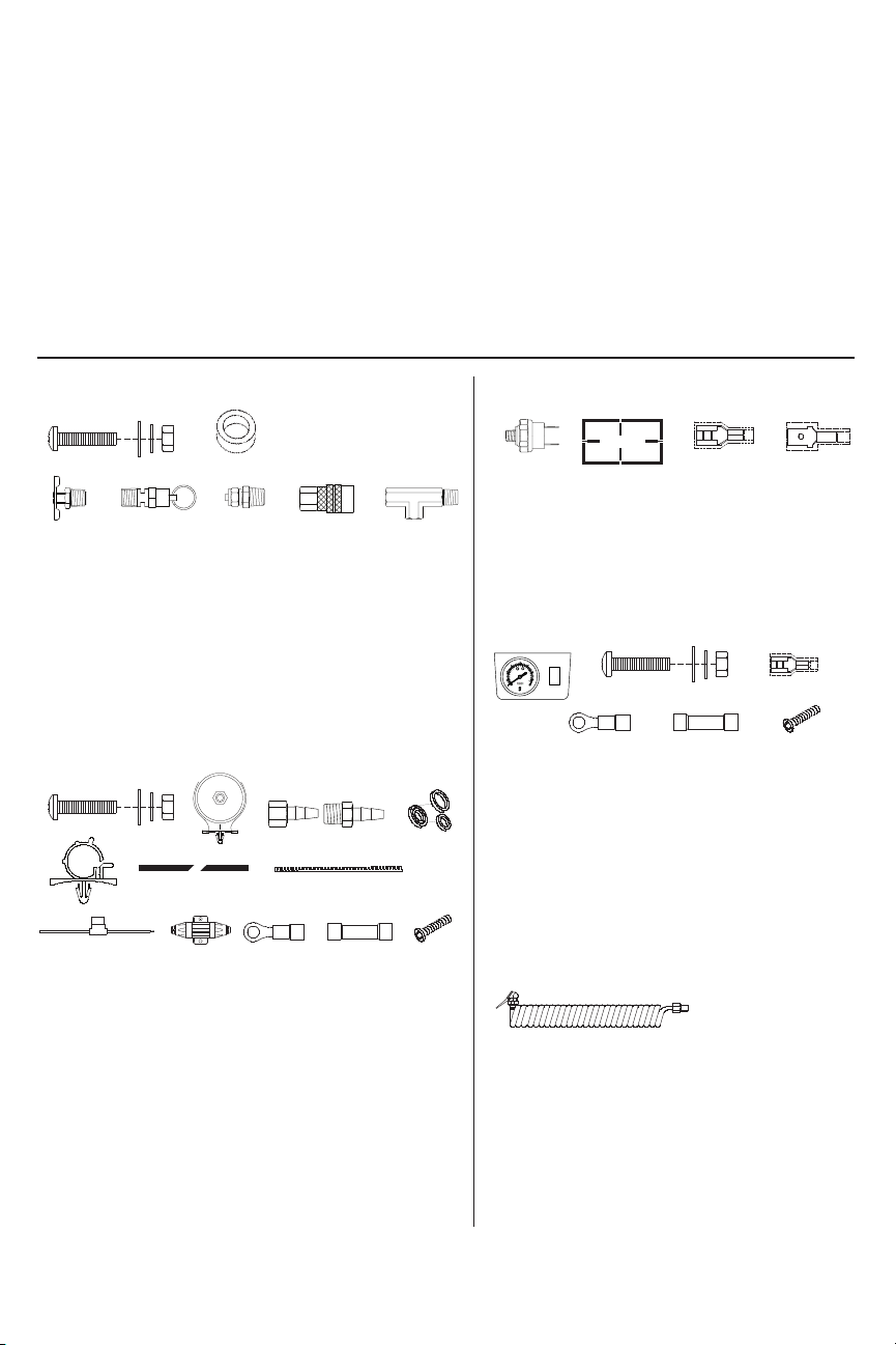
PARTS PACKAGES
Package #1 – Air Tank Installation:
A
BLCMD
F
G H I J
E
A. Mounting Bolts (4pcs)
B. Flat Washers (8pcs)
C. Locking Washers (4pcs)
D. Nuts (4pcs)
E. Rubber Tank Mount Bushings (6pcs)
F. 1/4” NPT Drain Cock (1pc)
G. 1/4” NPT 175 PSI Safety Valve (1pc)
H. 1/4” NPT Compression Fittings (4pcs)
I. 1/4” NPT F Quick Connect Coupler (1pc)
J. T-Fitting – (1/4” M x 1/4” F x 1/8” F NPT) (2pcs)
Package #2 – Compressor Installation:
K
N O P Q
R S T
U V W
X
Y
K. Mounting Bolts (4pcs)
L. Flat Washers (8pcs)
M. Locking Washers (4pcs)
N. Nuts (4pcs)
O. Remote Mount Air Filter Assemblies (2pcs)
P. Remote Mount Air Filter Fittings for
Compressor and Air Filters (2pcs)
Q. 2-pack of Replacement Air Filters (2pcs)
R. Leader Hose Bracket Clips (2pcs)
S. Air lines for Remote Mounting Air Filter (2pcs)
T. 4-inch Strip of continuous Grommet Material (2pcs)
U. Fuse Holder & 20 ft. 12 Gauge Wire (1pc)
V. 60-amp Tube Style Fuse (1pc)
W. 12-gauge Ring Terminal (1pc)
X. 12-gauge Butt Connectors (2pcs)
Y. Self-tapping Screws (2pcs)
Package #3 – Pressure Switch & Relays:
Z AA
86
87
30
85
BB
CC
Z. Pressure Switch
(110 PSI on, 145 PSI off) (1pc)
AA. 40-amp Relays (2pcs)
BB. Female Terminals (10pcs)
CC. Male Spade Terminals (10pcs)
Package #4 – Gauge Panel Installation:
DD EE FF GG HH II
0
2
5
2
5
1
1
0
1
0
3
2
3
5
5
0
0
JJ
KK
LL
DD. Dash Panel Gauge with ON/OFF Switch (1pc)
EE. Mounting Bolts (2pcs)
FF. Flat Washers (4pcs)
GG. Locking Washers (2pcs)
HH. Nuts (2pcs)
II. Push-on Female Terminals (2pcs)
JJ. 12-gauge Ring Terminal (1pc)
KK. 12-gauge Butt Connector (1pc)
LL. Self-tapping Screw (1pc)
Package #5 – Coil Hose with Couplers:
MM
MM. 30-ft. Coil Hose with 1/4” NPT
Quick Connect Coupler and 1/4” NPT stud
USER MANUAL
SUPER DUTY ONBOARD AIR SYSTEM
P/N 10008, 10009
OBA PLUMBING DIAGRAM
Typical System Configuration, May Vary Depending on Installation
PARTS PACKAGES (CONT’D)
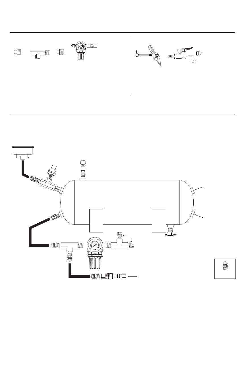
Package #6 – Accessories:
NN PP RR SS
OO
QQ
Package #7 – Air Tools / Carry Bag:
NN. 1/8” BSP F to 1/4” NPT M Adaptors
(for air locker use) (2pcs)
OO. T-Fitting (1/4” M x 1/4” F x 1/4” F NPT (1pc)
PP. 1/4” M NPT Plug (for regulator port block-off) (1pc)
QQ. 0-150 PSI Air Pressure Regulator Assembly (1pc)
RR. Ination Gun with 0-200 PSI
Pressure Gauge with 1/4” NPT
Quick Connect Stud (1pc)
SS. Blowgun Tool (1pc)
TT. Air Tool Carry Bag (1pc)
2.0 GALLON AIR TANK & PLUMBING (USE CONTENTS OF PARTS PACKAGE #1)
Your 2.0 Gallon air tank is shorter than most tanks on the market and has been designed for use with vehicles
without much room underneath. The tank comes with six 1/4” NPT port openings to allow installation in many
congurations on your vehicle. To insure safe and trouble-free use of your air tank, we strongly recommend
that you install the supplied drain cock and a safety pressure relief valve. (See Figure 1)
Plumbing Diagram:
(Figure 1)
Dash Panel
Gauge
Pressure
Switch
Safety
Valve
2.0
Gallon
Tank
Drain
BSP Adaptors
90
125
75
150
•
•
••
•
50
175
••
•
2
5
••
200
•
0
220
r
ba
psi
To Air Lockers
Cock
Leader Hose
From Compressor #1
Leader Hose
From Compressor #2
Compression
Fitting
Quick Connect
Couplers
Coil Hose
Tank Fittings:
Install the supplied ttings for the air tank in areas where they are most appropriate for your installation
using thread sealant or Teon tape. (Not all installations will be plumbed exactly as shown in schematic.)
Make sure that the safety valve is installed in the top most position on the tank, and that the drain cock is
installed in the lowest position on the tank if the tank is to be installed in any other position than upright on
the tank’s mounting legs. Be sure that all ttings are accessible later in the installation process since you
will have to plumb air lines to each tting as needed to utilize the air tank.
USER MANUAL

SUPER DUTY ONBOARD AIR SYSTEM
2.0 GALLON AIR TANK & PLUMBING (CONT’D)
Mounting the Tank:
We have included 6 pieces of rubber bushings in your tank mounting hardware. You have the option of
using two layers of rubber bushings on one of your tank lags to slightly tilt tank toward the drain cock port to
improve drainage properties. Use the provided longer bolts, and corresponding washers, lock washers and
nuts to mount the tank to a suitable chassis or other place on your vehicle.
IMPORTANT:
- Tank is rated for 150 PSI maximum working pressure.
- Tank is NOT to be used as a breathing device.
- Bleed pressure from tank before servicing or adding attachments.
- Use only attachments or tools rated for 150 PSI working pressure or less.
CAUTION! DO NOT PRESSURIZE YOUR TANK UNTIL YOU HAVE INSTALLED
ALL NECESSARY PORT FITTINGS AND ACCESSORIES.
- Apply sealant to threads of ttings prior to assembly and tighten each part with a wrench.
- Do not over tighten if your port ttings are made from brass, since brass threads can be stripped.
- Always release air from tank before servicing.
WARNING: FAILURE TO DRAIN TANK AND REMOVE CONDENSATION
WILL CAUSE TANK TO RUST PREMATURELY.
- To remove accumulated condensation inside the tank, bleed pressure from tank until pressure is
approximately 5-20 PSI using drain cock
- Drain tank by opening the drain cock drain valve and close after draining tank.
- If drain cock valve is plugged, release all air pressure from tank, remove drain valve and clean, then reinstall.
IMPORTANT: Please observe air tank’s Date of Manufacture (stamped on tank leg).
Replace air tank 2 to 5 years from date air tank was rst used, or use the date of manufacture as reference.
Adhering to air tank draining guidelines will prolong the life of your air tank.
PLEASE NOTE: RUSTED TANKS CAN FAIL CAUSING EXPLOSIONS OR FATAL INJURIES.
Discard tank immediately if tank is rusted.
SAFETY VALVE: When using a safety pressure relief valve, point the safety pressure relief valve away
from your body when releasing air. Use the pull ring on the safety relief valve to vent pressure from the
tank before servicing.
USER MANUAL
 Loading...