


444C DUAL PERFORMANCE VALUE PACK
(Chrome)
PART NO. 44432
IMPORTANT:
It is essential that you and any other operator of this product read and understand the contents of this manual before installing and using this product.
SAVE THIS MANUAL FOR FUTURE REFERENCE
USER MANUAL

444C DUAL PERFORMANCE VALUE PACK
IMPORTANT SAFETY INSTRUCTIONS
CAUTION - To reduce risk electrical shock:
-Do not disassemble. Do not attempt repairs or modifications. Refer to qualified service agencies for all service and repairs.
-Do not use this product in or area where it can fall or be pulled into water or other liquids.
-Do not reach for this product if it has fallen into liquid.
-Use compressors with 12-volt DC systems only.
-This product should never be left unattended during use.
WARNING - To prevent injury:
-Never allow children to operate compressors. Close supervision is necessary when this compressor is being used near children.
-Compressors will become very HOT during and immediately after use. Do not touch any part of them with bare hands during and immediately after use.
-Do not use this product near flames or explosive materials or where aerosol products are being used.
-Do not operate this product where oxygen is being administered.
-Do not pump anything other than atmospheric air.
-Never use this product while sleepy or drowsy.
-Do not use any tools or attachments without first determining maximum air pressure for that tool or attachment.
-Never point any air nozzle or air sprayer toward another person or any part of the body.
-Each 444C air compressor is equipped with an Automatic Reset Thermal Protector, and can automatically restart after the thermal protector resets. Always cut off power source when thermal protector becomes activated.
-Wear safety glasses or goggles when installing this product.
-Use only in well ventilated areas.
INSTALLATION
Please read and follow the installation instructions carefully to avoid injury or damage to the compressor or your vehicle.
Each of our air compressors and parts have been carefully produced and packaged. Before you begin installation, please familiarize yourself with Installation Parts List (Fig. 1) of this manual.
Guidelines for Selecting Mounting Location:
The selection of proper mounting location for your air compressor will help ensure a long and trouble free compressor service life. Please pay close attention to the following guidelines:
1.Select a FLAT AND SECURE location where the compressors can be mounted.
2.To maximize air compressor performance, locate compressor as CLOSE TO THE BATTERY as possible so that length of positive lead wire required is at a minimum.
3.Choose mounting location that is as cool as possible and AWAY FROM HEAT SOURCES. The cooler the ambient temperature, the less chance the compressor will overheat.
4.These compressors are moisture & splash resistant, but NOT WATERPROOF.
Do not mount compressor in locations where the unit is likely to come in contact with water.
5.For remote filter mounting, select compressor mounting location where air line can be routed from compressor air inlet to remote inlet air filter. Make sure Remote Inlet Air Filter is located in a dry location, away from the elements.
6.You will also want to select compressor mounting location where the leader hose bracket can be mounted to secure the leader hose.
7.If it is necessary to mount air compressors further away from the battery, such as inside your vehicle or on the chassis of a pickup, use a minimum 4 AWG positive lead wire for remote installation.
8.Do not mount compressor near areas where flammable liquids are stored.
9.VIAIR suggests the use of a 40-amp rated relay with each compressor (not included with this kit).
10.VIAIR also suggests the use of a 200 PSI maximum pressure switch to regulate on & off pressures. Pressure switch is not included with this kit.
USER MANUAL
444C DUAL PERFORMANCE VALUE PACK
MOUNTING AND WIRING
1.Disconnect ground cable from vehicle’s battery.
2.Temporarily position the air compressor in the location where it will be mounted.
3.Route ground wire to the negative post of the battery or to an appropriate grounding point and cut ground wire to length as needed.
4.Mount each air compressor with the four sets of bolts, nuts, washers, and locking washers provided. (See Fig. 2 for Mounting Instructions) Use of thread sealant is recommended.
5.NOTE: For Remote Inlet Air Filter Installation, refer to Remote Inlet Air Filter Installation Instruction included in the Remote Inlet Air Filter Pack.
6.Your air compressors come with heavy duty heat-resistant
leader hose with 1/4” NPT fittings. This leader hose is designed to prolong the life of your air line. Do not remove the leader hoses from the air compressors.
7.IMPORTANT: Please note, the leader hose that comes with your compressor has a built-in inline check valve. Do Not remove inline check valve from leader hose.
8.Select proper location to mount leader hose with hose bracket provided.
Avoid locations where leader hose may become tangled with wires and other hoses.
9.To mount hose bracket, drill hole with 3/16” drill bit and push self–anchoring hose bracket pin into hole. Route leader hose through hose bracket and secure hose by pressing bracket clamp into locked position.
10.To remove hose from the hose bracket, simply press down on the hose clamp release tab to release bracket clamp. (Fig. 3)
11.Connect compressor positive lead wire to one of the leads of your pressure switch.
12.Make sure that your compressor setup is properly fused. Both 444C compressors will pull
38 amps at peak draw.
13.Always locate fuse as close as possible to power source.
14.Before connecting to power source, re-check to make sure that all connections are made properly.
15.Connect and test compressor system by running the compressor for a short time to build up pressure in your air tank.
16.Once air pressure reaches preset cut out pressure of your pressure switch (pressure switch not included) the compressor will shut off. Inspect all air line connections for leaks with soap and water solution. If a leak is detected, the air line may not be cut squarely or pushed all the way in.
Repair connections as needed.
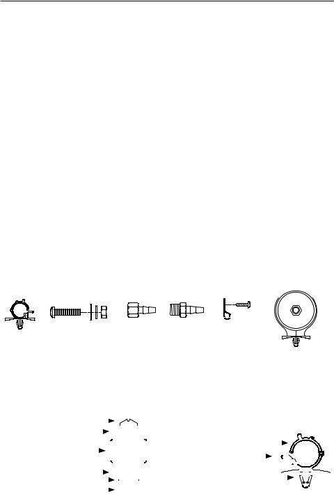
(Fig. 1) 444C Compressor Installation Parts List:
A |
B |
C D E |
F |
G |
I |
|
|||||
|
|
|
|
|
H |
A. Hose Bracket (1pc) x2 |
|
|
|
|
|
B. Mounting Bolts (4pcs) x2 |
|
|
J |
||
C.Flat Washers (8pcs) x2
D.Locking Washer (4pcs) x2
E.Nuts (4pcs) x2
F.3/8” NPT F x 1/2” Barbed Fitting (1pc) x2
G.3/8” NPT M x 1/2” Barbed Fitting (1pc) x2
H.Air Line Clips (3pcs) x2
I.Screws (3pcs) x2
J.Remote Inlet Air Filter with Filter Element (1pc) x2
(Fig. 2) Compressor |
B |
|
|
|
|
|
|
|
|
|
|
|
|
(Fig. 3) Leader Hose Bracket |
|
|
|
|
|
|
|
|
|
|
|
|
|
|
|
|||||||||
|
|
|
|
|
|
|
|
|
|
|
|
|
|
|
|
|
|
|
|
|
|
|
|
|
|
|||||||||||||
|
|
|
|
|
|
|
|
|
|
|
|
|
|
|
|
|
|
|
|
|
|
|
||||||||||||||||
C |
|
|
|
|
|
|
|
|
|
|
|
|
|
|
|
|
|
|
|
|
|
|
|
|
||||||||||||||
Mounting Hardware |
K |
|
|
|
|
|
|
|
|
|
|
|
|
|
|
|
|
L. Hose Clamp |
L |
|
|
|
|
|
|
|
|
|
|
|
|
|
|
|
|
|
|
|
|
|
|
|
|
|
|
|
|
|
|
|
|
|
|
|
|
|
|
|
|
|
|
|
|
|
|
|
|
|
|
|
|
|
|
||||
|
|
|
|
|
|
|
|
|
|
|
|
|
|
|
|
|
|
|
|
|
|
|
|
|
|
|
|
|
|
|
|
|
|
|
|
|||
|
|
|
|
|
|
|
|
|
|
|
|
|
|
|
|
|
|
|
|
|
|
|
|
|
|
|
|
|
|
|
|
|
|
|
|
|||
B. Mounting Bolt |
|
|
|
|
|
|
|
|
|
|
|
|
|
|
|
|
|
M. Clamp Release Tab |
M |
|
|
|
|
|
|
|
|
|
|
|
|
|
|
|
|
|
|
|
C. Flat Washer |
C |
|
|
|
|
|
|
|
|
|
|
|
|
|
|
|
|
N. Self Anchoring Pin |
|
|
|
|
|
|
|
|
|
|
|
|
|
|
|
|
|
|
|
|
D. Locking Washer |
D |
|
|
|
|
|
|
|
|
|
|
|
|
|
|
|
|
|
N |
|
|
|
|
|
|
|
|
|
|
|
|
|
|
|
|
|
|
|
|
|
|
|
|
|
|
|
|
|
|
|
|
|
|
|
|
|
|
|
|
|
|
|
|
|
|
|
|
|
|
|
|
|
|
||||
E. Nut |
|
|
|
|
|
|
|
|
|
|
|
|
|
|
|
|
|
|
|
|
|
|
|
|
|
|
|
|
|
|
|
|
|
|||||
E |
|
|
|
|
|
|
|
|
|
|
|
|
|
|
|
|
|
|
|
|
|
|
|
|
|
|
|
|
|
|
|
|
|
|
|
|
|
|
K. Vibration Isolator |
|
|
|
|
|
|
|
|
|
|
|
|
|
|
USER MANUAL |
|
|
|
|
|
|
|
|
|
|
|
|
|
|
|
|
|
|
|
|
|||
|
|
|
|
|
|
|
|
|
|
|
|
|
|
|
|
|
|
|
|
|
|
|
|
|
|
|
|
|
|
|
|
|
|
|
||||
 Loading...