

Viadrus U 22 C, U 22 D User Manual

VIADRUS U 22 C/D
Manual for boiler operation and installation
GB_2015_24
GB_2017_14

Contents
page
1 Usage and advantages of the boiler ............................................................................................................................................................. 3
2 Technical data of the boiler .......................................................................................................................................................................... 3
3 Description................................................................................................................................................................................................... 4
3.1 Construction of the boiler ................................................................................................................................................................... 4
3.2 Regulating and security elements ...................................................................................................................................................... 7
4 Placing and installation ................................................................................................................................................................................ 7
4.1 Regulations and instructions .............................................................................................................................................................. 7
4.2 Placing possibilities ............................................................................................................................................................................ 7
5 Order, delivery and assembly ...................................................................................................................................................................... 9
5.1 Order ................................................................................................................................................................................................. 9
5.2 Delivery and accessories ................................................................................................................................................................... 9
5.3 Assembly techniques ......................................................................................................................................................................... 9
5.3.1
Boiler drum installation ..................................................................................................................................................... 10
5.3.2
Jacket assembly ............................................................................................................................................................... 10
5.3.3
Filling of the heat system with water ................................................................................................................................. 11
6 Putting into operation – instructions for a contractual service organization ................................................................................................. 12
6.1 Control operation before starting ...................................................................................................................................................... 12
6.2 Putting the boiler into operation ........................................................................................................................................................ 12
6.3 Boiler transformation from „solid fuels“ to „gas and liquid fuels“ and retroactively ............................................................................. 12
7 User’s boiler service .................................................................................................................................................................................. 12
7.1 Heating up ....................................................................................................................................................................................... 13
7.2 Operation ......................................................................................................................................................................................... 14
8 Maintenance .............................................................................................................................................................................................. 14
9 IMPORTANT NOTICE ............................................................................................................................................................................... 14
10 Instructions for product liquidation after its operating life ............................................................................................................................ 15
11 Warranty and defect liability ....................................................................................................................................................................... 15
12 Product fiche .............................................................................................................................................................................................. 16
3
Dear customer,
thank you for buying the general – purpose VIADRUS U 22 boiler and thus showing belief in the company VIADRUS a.s.
At first read this operating manual (especially Chapter Nr. 7 – User’s boiler service and Chapter Nr. 9 – Important notice) to get used to a proper
usage with your new product from the very beginning. We request to maintain the further mentioned information and particularly to perform the
prescribed annual checks by an authorized specialized company by which a long – time failure – free operation of your boiler - to your and our
satisfaction - is secured.
The boiler VIADRUS U 22 is a general – purpose cast iron sectional low – pressure boiler intended for burning of:
- solid fuels coke, anthracite, wood commercial marking VIADRUS U 22 C
wood (optionally coke and anthracite) commercial marking VIADRUS U 22 D
- gas fuels natural gas commercial marking VIADRUS U 22 P
- liquid fuels boiler oil extra light – TOEL commercial marking VIADRUS U 22 N
Burning of other materials such as plastic is unallowable.
The boiler VIADRUS U 22 is not intended for the Czech market.
1 Usage and advantages of the boiler
Two and three – sectional size of the boiler VIADRUS U 22 is appropriate for heat source reconstruction in self – contained flats, for smaller
residential and recreational facilities. Bigger sizes of the boiler meet the requirements of heating the family houses, shops, schools, etc.
The boiler is produced as hot – water with natural and forced circulation of heat water and operational overpressure to 800 kPa (8 bar).
The VIADRUS U 22 D boiler is different from the VIADRUS U 22 C boiler version by its enlargement of the stoke hole so that it is possible to
burn even bigger clogs up to the average of 220 mm. By burning wooden logs the heat work difficulty is considerably reduced and the service
quality is increased. The amount of ash is also substantially smaller and it is possible to further use it as fertilizer.
Advantages of the boiler:
1. High operating life of cast iron exchanger and all other parts with respect to the quality of used materials.
2. Design approved in the long term.
3. Elaborate production technology on automatic forming lines with consistent and approved quality of the production process (ISO 9001,
ISO 14 001).
4. Efficiency of coke and anthracite burning – 75 – 80 %, efficiency of wood burning – 75 %.
5. Simple service and maintenance.
6. Low demandingness for chimney draught
7. Power gradation according to the sections
8. Possibility of boiler transformation of burning of solid fuels to gas or liquid fuels or vice versa.
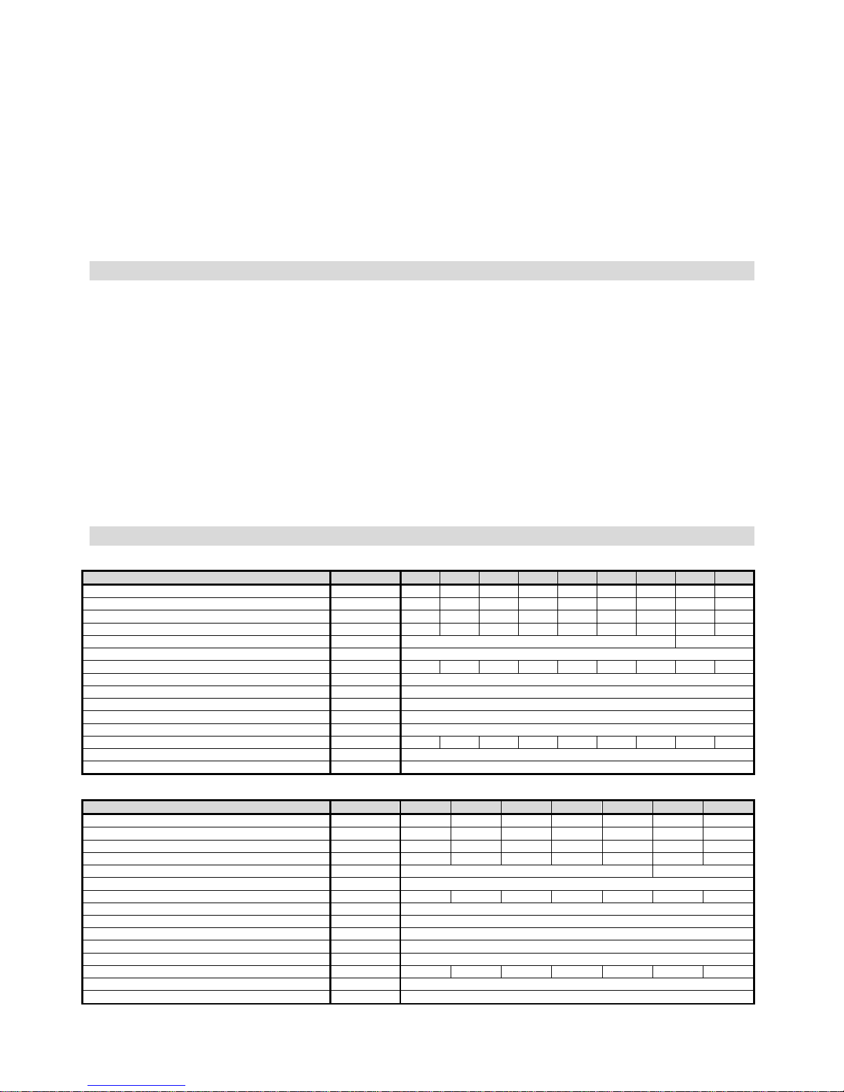
2 Technical data of the boiler
Tab. №. 1 Dimensions, technical parameters of the boiler VIADRUS U 22 C
Section number
pieces
2 3 4 5 6 7 8 9 10
Weight kg 198 218 252 282 312 347 377 417 448
Water space volume l 26,1 31,5 36,2 40,9 45,6 50,3 55,0 59,7 64,4
Firing chamber volume l 21 34 47 60 73 86 99 112 125
Firing chamber depth mm 149 244 339 434 529 624 719 814 909
Diameter of smoke socket mm 156 176
Boiler dimensions: - height x width mm 974 x 520
- depth mm 560 655 750 845 940 1035 1130 1225 1320
Water operating overpressure kPa (bar) 400 (4)
Testing water overpressure kPa (bar) 800 (8)
Hydraulic loss - See Fig. №. 1
Recommended heat water operating temperature °C 60-90
Noise level dB Not exceeding the level of 65 dB (A)
Minimum chimney draught mbar 0,12 0,14 0,16 0,18 0,20 0,22 0,24 0,26 0,28
Boiler connections - heat water DN 50
- returnable water DN 50
Tab. №. 2 Dimensions, technical parameters of the boiler VIADRUS U 22 D
Section number
pieces
4 5 6 7 8 9 10
Weight kg 250 274 304 340 370 410 441
Water space volume l 35,2 38,9 43,6 48,3 53 57,7 62,4
Firing chamber volume l 47 60 73 86 99 112 125
Firing chamber depth mm 339 434 529 624 719 814 909
Lightness of the stove - pipe mm 156 176
Boiler dimensions: - height x width mm 974 x 520
- depth mm 750 845 940 1035 1130 1225 1320
Water operating overpressure kPa (bar) 400 (4)
Testing water overpressure kPa (bar) 800 (8)
Hydraulic loss - See Fig. №. 1
Recommended heat water operating temperature °C 60-90
Noise level dB Not exceeding tle level of 65 dB (A)
Minimum chimney draught mbar 0,16 0,18 0,20 0,22 0,24 0,26 0,28
Boiler connections - heat water DN 50
- returnable water DN 50
4
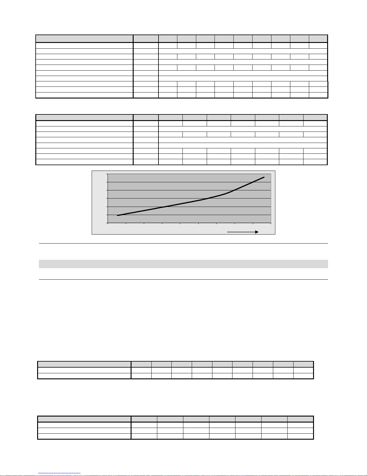
Tab. №. 3 Heat - technical parameters of the boiler at COKE and ANTHRACITE burning
granularity 30 – 60 mm heating value: 26 - 30 MJ. kg-1
Section number 2 3 4 5 6 7 8 9 10
Rated power kW 11,7 17,7 23,3 29,1 34,9 40,7 46,5 52,3 58,1
Efficiency % 75 - 80
Orientation fuel consumption – coke kg.h
-
1
1,89 2,87 3,77 4,71 5,65 6,59 7,53 8,47 9,41
Heating value – coke MJ. kg
-
1
27,8
Orientation fuel consumption – anthracite kg.h
-
1
1,98 3,0 3,95 4,93 5,92 6,9 7,88 8,87 9,85
Heating value – anthracite MJ. kg
-
1
28,31
Product of consumption temperature °C max. 280
Energy efficiency class D D C C C B B B B
Energy efficiency index 74 74 76 78 79 82 82 82 82
Season energy efficiency % 75,3 77,2 79,0 80,8 82,1 84,7 85,0 84,9 85,1
Tab. №. 4 Heat technical parameters of the boiler at WOOD burning
humidity 15 - 25 % heating value: 12 - 15 MJ. kg-1
Section number
4 5 6 7 8 9 10
Rated power kW 20 25 30 35 40 45 49
Efficiency % 75
Orientation fuel consumption kg.h
-
1
6,4 8,0 9,59 11,19 12,79 14,39 15,67
Heating value MJ. kg
-
1
15,01
Product of consumption temperature °C max. 320
Energy efficiency class B B A A+ A B A
Energy efficiency index 89 92 95 98 94 89 92
Season energy efficiency % 63,6 65,6 67,6 69,7 66,6 63,5 65,5
0
50
100
150
200
250
300
15 20 25 30 35 40 45 50 55 60
Fig. №. 1 Hydraulic loss of the boiler drum
3 Description
3.1 Construction of the boiler
The main part of the boiler is the cast iron section boiler drum made of grey cast iron according to ČSN 42 2415 or ČSN 42 2420. Pressure
parts of the boiler correspond to the demands on solidity according to CSN 07 0240 and CSN 07 0245.
The boiler drum consists of sections with the help of pressured boiler nipples and is secured with boiler screws. The sections create burning and
ash space, water space and a convective part. Heat water input and output are situated at the back part of the boiler.
The back section of the boiler has a smoky chimney – pot and a heat water flange in the upper part, and a returnable water flange with a socket
for impregnating and clearing plug. Stoker and ash door and a firebox door under them are fixed to the front section.
The whole boiler drum is isolated with a stifling, mineral isolation that reduces losses by sharing heat into the surroundings. The steel jacket is
fitted in colour with a quality comaxite paint.
At seven to ten – sectional size of the VIADRUS U 22 C boiler two tapes of medium sections are used: at the front part of the boiler the sections
are without a molding and in the back part with a molding. The molding closes the burning space and carries back the flame and product of
consumption from the back space to the front part of the boiler, i.e. by the back path in smoky draughts it is perfectly taken advantage of the
product of consumption heat.
Number of sections without and with a molding is mentioned in the following tab:
Tab. №. 5 Medium sections of the VIADRUS U 22 C boiler
Size of the
boiler
in sections
2 3 4 5 6 7 8 9 10
Medium section with a molding - 1 2 3 4 4 5 5 6
Medium section without a molding - - - - - 1 1 2 2
At the VIADRUS U 22 D boiler three types of medium sections are used: in the front part of the boiler (except the four – section size) there is a
section with a recess for easier fuel inserting to the average up to 220 mm, then sections without a molding, in the back part with a molding. The
molding closes the burning space and carries back the flame and product of consumption from the back space to the front part of the boiler, i.e.
by the back path in smoky draughts it is perfectly taken advantage of the product of consumption heat.
Tab. №. 6 Medium sections of the VIADRUS U 22 D boiler
Size of the
boiler
in sections
4 5 6 7 8 9 10
Medium section with a recess - 1 1 1 1 1 1
Medium section with a molding 2 2 3 4 5 5 6
Medium section without a molding - - - - - 1 1
Pa
Power in kW

5
Fig. №. 2 Design of the VIADRUS U 22 C boiler
– figure sump
– pot
– pot
– pot
with isolation
– clearing plug
Thermomanometer
Draught governor
Upper part of the jacket with
isolation Stoker door
Stoker door closure
Air rose
Ash door
Ash door closure
Stifling
Hanging pin Adjusting screw of the
stifling

6
Fig. №. 3 Design of the VIADRUS U 22 D boiler
Thermomanometer
Draught governor
Upper part of the jacket with
isolation
Stoker door
Stoker door closure
Air rose
Ash door Ash door closure Stifling Hanging pin Adjusting screw of the
stifling
– figure sump
– pot
– pot
– pot
ter with a
– clearing plug
7
3.2 Regulating and security elements
The smoky flap of the smoky chimney – pot regulates the climb of the product of consumption from the boiler to the chimney. It is regulated with
the handle with a rod in the upper left part of the boiler next to the stoker hole.
Stifling of the ash door regulates the inflow of the combustion air under the grate of the boiler. It is regulated by the draught governor or
manually with an adjusting screw of the stifling.
The air rose of the stoker door serves for carrying the secondary air to the burning space. To control the rose it is necessary with respect to the
higher surface temperature of the stoker door to use an instrument that is part of the delivered tools.
The cleaning cover of the smoky chimney – pot located in its bottom part serves for cleaning the embedded waste product caused by burning.
There are barriers of the smoky channel between the front and medium sections above the stoker hole of the boiler VIADRUS U 22 C. It serves
for reducing the draw – away cross - section and for a better utilization of the product of consumption at the boilers of smaller power (2 – 5
sectional). They are used with a various cross – section width according to the sizes of the boilers in conformity with this tab.:
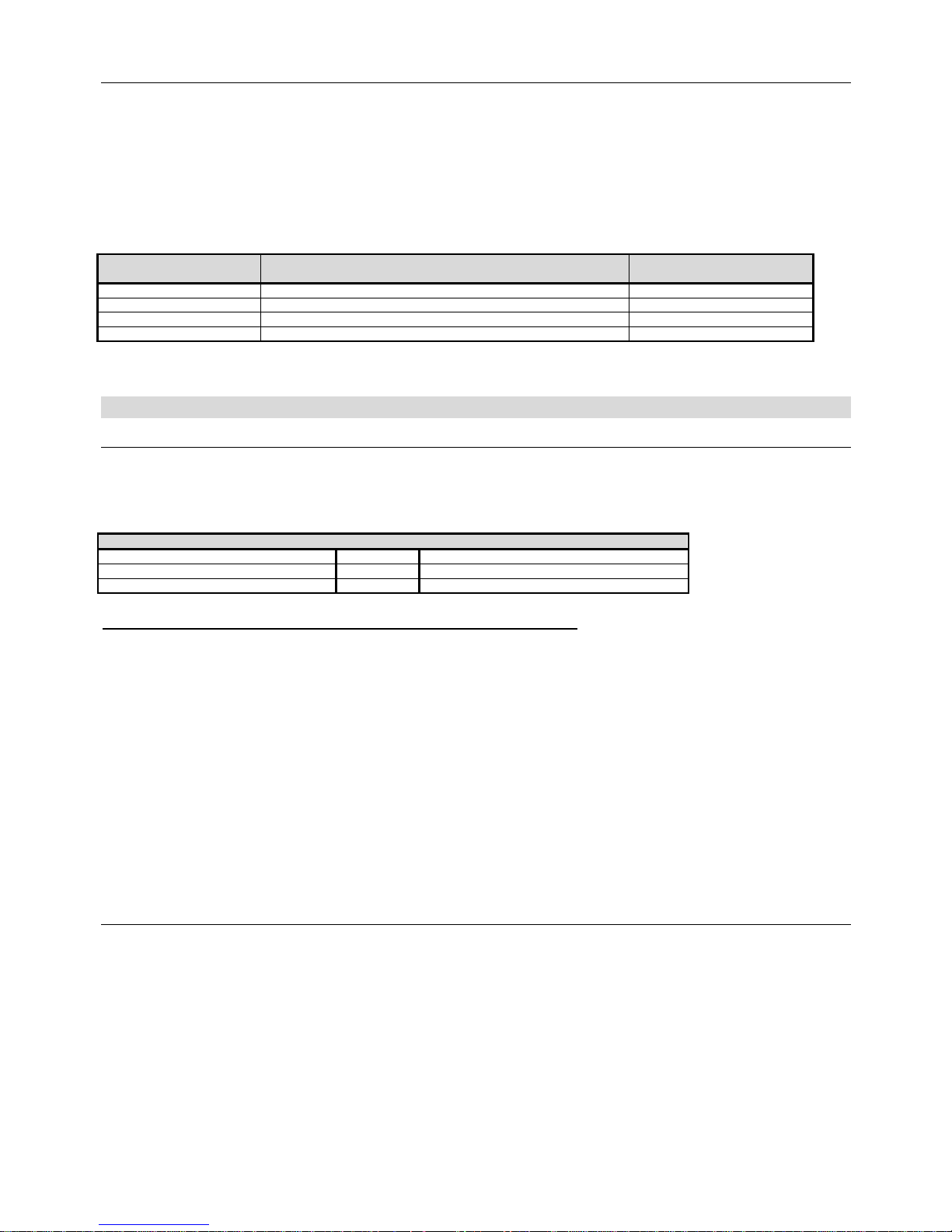
Tab. №. 7 Barriers of the smoky channel of the VIADRUS U 22 C boiler
Boiler section number
(pieces)
Cross – section of the smoky channel width (mm) Barrier number (pieces)
2 12 2
3 24 2
4 36 2
5 48 2
A thermomanometer in the control box serves as an associated device for measuring the temperature of the heat water and water pressure in
the heat system. The sump of the thermomanometer sensor is located in the upper part of the back boiler section.
4 Placing and installation
4.1 Regulations and instructions
The boiler for solid fuels can be installed by a company with a valid authorization to perform its installation and maintenance. For
installation a project in accordance with valid regulations must be executed.
The heating system must be filled with water, that meets the ČSN 07 7401 requirements, especially its harness must not exceed the
required parameters.
Tab. №. 8
Recommended values
Hardness mmol/l 1
Ca2+ mmol/l 0,3
Concentration of total Fe + Mn mg/l (0,3)*
*) recommended value
WARNING!!! The use of anti-freeze mixture is not recommended by the manufacturer.
a) to the heating system
ČSN 06 0310 Heating systems in buildings – Designing and installation
ČSN 06 0830 Heating systems in buildings – protecting device
CSN 07 0240 Warm water and low-pressure steam boilers. Basic regulations
CSN 07 0245 Warm water and low-pressure steam boilers. Warm water boilers with output up to 50 kW. Technical
requirements. Testing.
ČSN 07 7401 Water and steam for thermal energy equipments with working pressure up to 8 MPa.
b) to the chimney
ČSN 73 4201 Chimneys and flue gas ducting– designing, implementation and connection of fuel consumers.
c) regarding the fire regulations
ČSN 06 1008 Fire safety of heat installations.
EN 13501-1+A1 Fire classification of construction products and building elements – Part 1: Classification using test data from
reaction to fire tests
d) to the system of HWS heating
ČSN 06 0320 Heating systems in buildings – Hot water preparation – Designing and planning
ČSN 06 0830 Heating systems in buildings – Safety devices.
ČSN 75 5409 Water installations inside buildings.
4.2 Placing possibilities
Boiler positioning in the living space (including corridors) is prohibited!
A continuous air supply for burning and eventual ventilation must be ensured for the room where the boiler is installed.
The installation of the boiler must comply with all requirements of ČSN 06 1008.
Boiler placing with regard to fire regulations:
1. Placing on floor of flame resistant material (Pic.4)
- boiler to be put on a flame resistant backing exceeding the boiler platform over 20 mm at sides and only on the boiler drum depth.
- if the boiler is situated in a cellar we recommend to place it on a bedding of minimum 50 mm height.
2. Safety distance from the flammable materials
- when installing and operating the boiler it is necessary to keep a safety distance of 200 mm from the materials of combustibility grade
A1, A2, B and C (D);
- for easily combustible materials of combustibility grade E (F), which quickly burn and burn themselves even after removal of ignition
source (such as paper, cardboard, asphalt and tar paper, wood and wood-fiber boards, plastics, floor coverings) the safe distance has
to be doubled, i.e. to 400 mm;
- safe distance should be doubled as bulb where the grade of reaction to fire has not been proved.
8
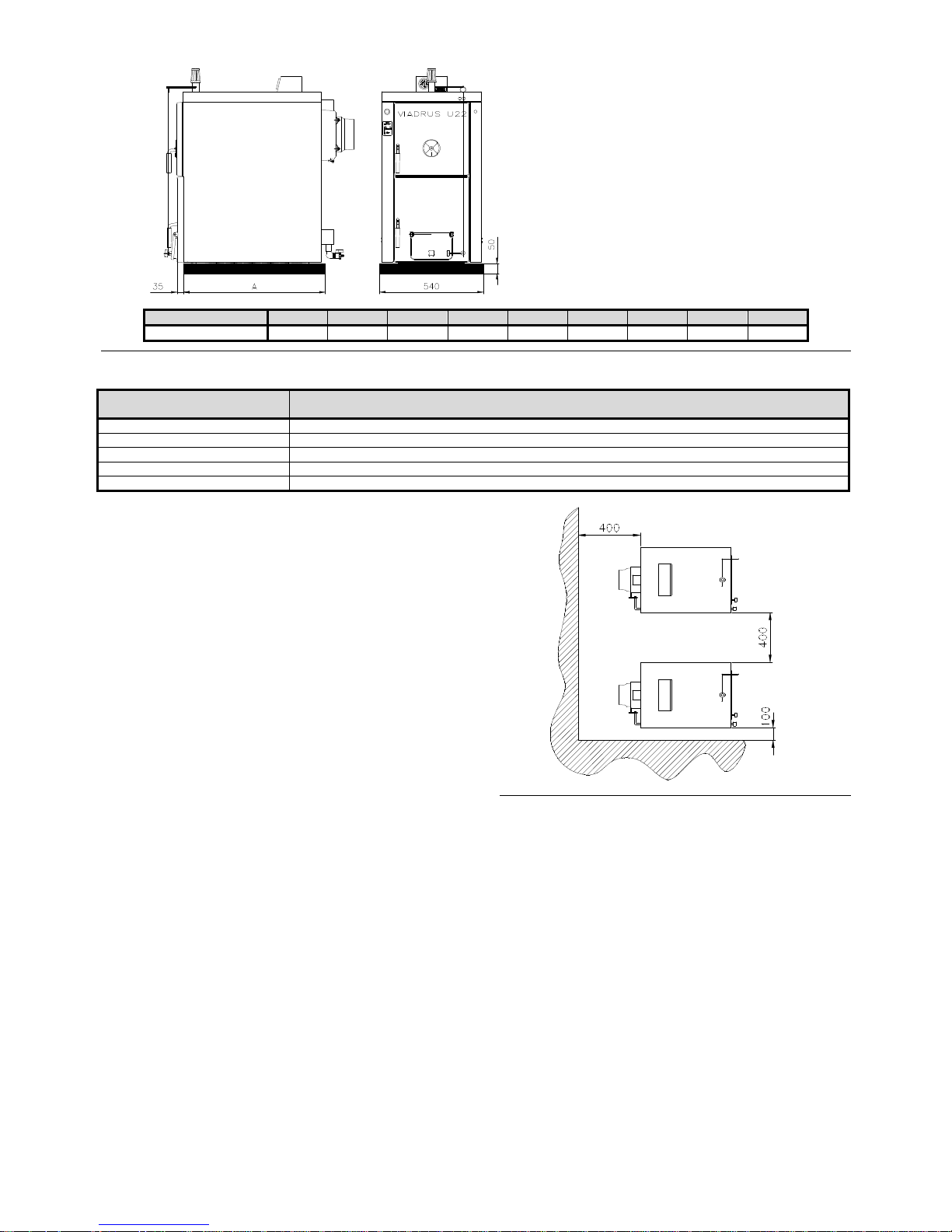
Section number
2 3 4 5 6 7 8 9 10
A [mm]
325 420 515 610 705 800 895 970 1085
Fig. №. 4 Bedding dimensions
Tab. №. 9 Grade of reaction to fire
Grade of reaction to fire
Examples of building materials and products included in the reaction to fire
(Extract from EN 13501-1 + A1)
A1
– incombustible
Granite, sandstone, concrete, bricks, ceramic tiles, mortars, fireproof plasters, …
A2
– combustible with difficulty
acumin, izumin, heraklit, lignos, boards and basalt felt, fibreglass boards,...
B
– hardly combustible
Beech and oak wood, hobrex boards, plywood, werzalit, umakart, sirkolit,...
C (D)
– medium combustible
Pinewood, larch, whitewood, chipboard and cork boards, rubber flooring,...
E (F)
– easily combustible
Asphaltboard, fibreboards, cellulose materials, polyurethane, polystyrene, polyethylene, PVC,…
The boiler placing with respect to the necessary handling
space:
- basic surroundings of AA5/AB5 according to ČSN 33 2000-1
ed. 2
- handling space of minimum 1000 mm in front of the boiler
must be maintained
- a minimum distance of 400 mm between the back part of the
boiler and the wall
- to maintain space for access to the back part of the boiler of
minimum 400 mm at least from one lateral face
- a minimum distance of 100 mm from the side wall
Fuel placing:
- it is disallowed to store fuel behind the boiler or to unload it
beside the boiler in the distance smaller than 400 mm
- it is disallowed to store fuel between two boilers in a boiler
room
- the producer recommends to keep distance of minimum 1000
mm between the boiler and fuel or to place the fuel to a
another room than that where the boiler is installed
Fig. №. 5 Boiler placing in a boiler room
9
5 Order, delivery and assembly
5.1 Order
In the order the following is needed to be specified:
1. Boiler design - VIADRUS U 22 C boiler
- VIADRUS U 22 D boiler
2. Boiler size.
3. Demands on optional accessories.
5.2 Delivery and accessories
The boiler is delivered according to the order in a manner that a complete boiler drum is located on the palette and a covered boiler jacket is
fixed on the side. The accessories are stored inside the boiler drum and is available after opening the stoker hole. The boiler is covered in the
transfer packing and must not be turned over during the transit, only a declination into sides for taking down of the boiler drum packing is
allowed.
Standard accessories for the boiler:
• cleaning tools (hook, brush with shaft, point, hanger)
• control box 1 piece
• thermomanometer 1 piece
• impregnating and clearing plug Js 1/2“ 1 piece
• draught regulator complete 1 piece
• closure Js 6/4“ 2 pieces
• rod with a control handle of the
smoky flap 1 piece
• control label of the smoky flap 1 piece
• stifling screw 1 piece
• connecting pin of the jacket 4 pieces
• fan-shaped washer 5 4 pieces
• nut M5 4 pieces
• washer 10,5 8 pieces
• nut M10 8 pieces
• flexible pins 3 x 26 1 piece
• split pin 2,5 x 32 1 piece
• washer 10,5 3 pieces
• bushings HEYCO 2 pieces
• blind flanges 6 pieces
• screws into metal C 4,8 x 13 4 pieces
• flange of heat water DN 50 1 piece
• flange of returnable water DN 50 with a socket Js 1/2“ for impregnating and clearing plug 1 piece
• well of thermostat 1 piece
• sealing φ 90 x 60 x 3 2 pieces
• operating key 1 piece
• hook 2 pieces
• socket 8 mm 2 pieces
• boiler operation and installation manual
5.3 Assembly techniques
Every heat source in an open heat system must be connected with an open expansion tank positioned at the highest point of the heat system.
The expansion tanks must be rated in the way that they can contain the changes in water volume resulting from heating and cooling.
The open expansion tanks must be equipped with non-closable bleeder and a overflow pipes. The overflow pipe must be designed in the way
that it safely drains off the maximum flow volume entering the system. This can be achieved by rating the overflow pipes by one DN higher than
that of the filling piping. The expansion tanks and their connecting pipes must be designed and positioned in the way that freezing is reliably
inhibited.
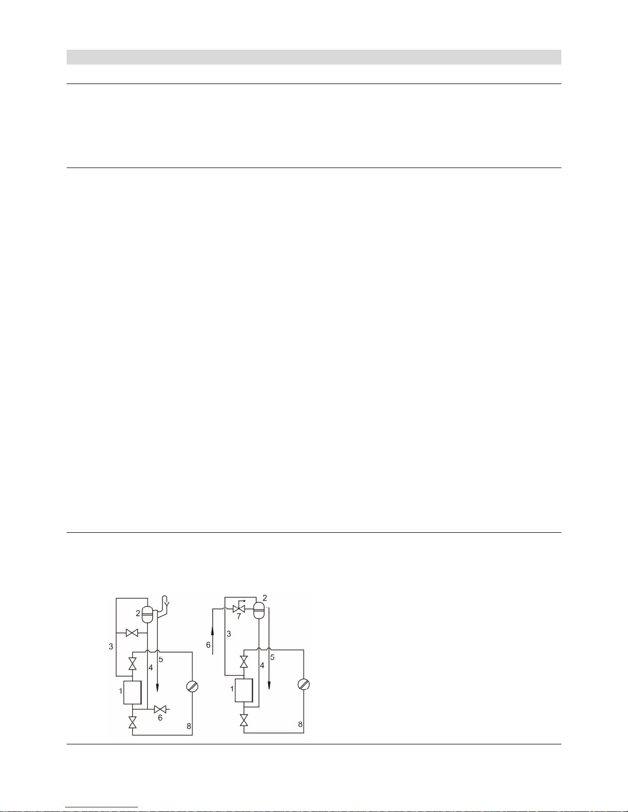
Fig. №. 6 The examples of open expansion tanks connection
1 Heat source
2 Expansion tank
3 Safety piping
4 Expansion piping
5 Overflow piping
6 Filling piping
7 Water level limiter
8 Reverse piping
 Loading...