

Viadrus K4 User Manual

VIADRUS K4
Manual for boiler operation and installation
GB_2017_24
GB_ 2015_31

Table of Contents
page
General Information
1
Produced Versions of the Boilers ............................................................................................................................................................. 3
2
Boiler Application and Benefits ................................................................................................................................................................. 3
3
Technical Data ......................................................................................................................................................................................... 4
4
Boiler Description ................................................................................................................................................................................... 15
4.1
4.2
4.3
4.4
4.5
4.6
Boiler Design ................................................................................................................................................................................... 15
Control Features .............................................................................................................................................................................. 15
4.2.1 Removing the front cover ........................................................................................................................................................... 15
Main Boiler Parts ............................................................................................................................................................................. 16
A diagram showing flue gas flow in the exchanger ........................................................................................................................... 18
Delivery and Accessory ................................................................................................................................................................... 18
Instructions before Putting into Operation ........................................................................................................................................ 18
User
5
Boiler Attendance by the User ................................................................................................................................................................ 19
5.1
5.2
5.3
5.4
5.5
5.6
5.7
6
7
8
9
Description of the Control ................................................................................................................................................................. 19
Modes of Operation ......................................................................................................................................................................... 19
Lockout condition codes................................................................................................................................................................... 21
Blocking codes ................................................................................................................................................................................. 22
Additional Functions ......................................................................................................................................................................... 23
5.5.1 LCD symbols test....................................................................................................................................................................... 23
5.5.2 Air purge function ...................................................................................................................................................................... 23
OpenTherm communication ............................................................................................................................................................. 23
5.6.1 History information ..................................................................................................................................................................... 23
Installer mode .................................................................................................................................................................................. 24
5.7.1 “tS” as Transparent Parameters mode (TSP) ............................................................................................................................. 24
5.7.2 “In” as Inquiry mode ................................................................................................................................................................... 24
5.7.3 “Hi” as History mode .................................................................................................................................................................. 25
5.7.4 “rES” as Reset of the History information ................................................................................................................................... 25
Maintenance .......................................................................................................................................................................................... 25
IMPORTANT NOTICES ......................................................................................................................................................................... 26
Instructions for Product Disposal After Its Service Life............................................................................................................................ 26
Warranty and Liability for Defects ........................................................................................................................................................... 27
Servicing
10 Placement and Installation ..................................................................................................................................................................... 28
10.1 Standards and regulations ............................................................................................................................................................... 28
10.2 Possible Placement ......................................................................................................................................................................... 29
10.3 Boiler Installation ............................................................................................................................................................................. 29
10.4 Connecting to the Heating System and Water Filling ........................................................................................................................ 31
10.5 Gas Connection ............................................................................................................................................................................... 31
10.6 Electric Power Supply Connection ................................................................................................................................................... 31
10.7 Condensate Discharge .................................................................................................................................................................... 31
10.8 Flue Gas Ducting ............................................................................................................................................................................. 31
10.9 Boiler Electrical Wiring ..................................................................................................................................................................... 32
10.9.1 Main components of boiler electrical equipment ......................................................................................................................... 32
10.9.2 Connection of the higher-level regulation and external boiler sensors ........................................................................................ 32
10.9.3 Connecting terminal ................................................................................................................................................................... 33
11 Flue Gas Ducting ................................................................................................................................................................................... 38
11.1 Flue gas ducting – examples of correct connection of flue duct and air supply ................................................................................. 39
11.2 Flue gas ducting – examples of incorrect connection of flue duct and air supply .............................................................................. 39
11.3 STARR D80 and FLEX 80 system connection ................................................................................................................................. 39
11.3.1 STARR, 2 x D 80 mm flue ducting diagram ................................................................................................................................ 40
11.3.2 FLEX, 2 x D 80 mm flue ducting diagram ................................................................................................................................... 41
11.4 LIK 60/100, 80/125 system connection ............................................................................................................................................ 42
11.4.1 Diagram for flue gas ducting of the LIK type, version 60/100 mm (max. length 5 m), or 80/125 .................................................. 43
11.5 Pressure Losses of Chimney Flue Elements in Case of VIADRUS K4 Boiler Usage ........................................................................ 44
12 Commissioning ...................................................................................................................................................................................... 44
12.1 Instructions before Putting into Operation ........................................................................................................................................ 45
12.2 Boiler Setting ................................................................................................................................................................................... 46
12.3 Conversion to a different type of fuel ................................................................................................................................................ 47
12.4 Boiler Electronics Setting ................................................................................................................................................................. 47
12.4.1 K4GXH24X - Honeywell electronics parameters set in the manufacturing factory (service parameters list neXsys S4962V3224)
12.4.2 K4GXH33X - Honeywell electronics parameters set in the manufacturing factory (service parameters list neXsys S4962V3224)
13 Servicing Inspection of the Boiler ........................................................................................................................................................... 50
.................................................................................................................................................................................................. 48
.................................................................................................................................................................................................. 49
2

General Information
X
1
Exchanger:
G:
X
Water heating:
1:
X
3
Electrical equipment:
H:
X
Output:
24:
X
Fuel: Z:
X
Cover color:
W:
Dear Customer
Thank you for your purchase of the VIADRUS K4 boiler and for your confidence in VIADRUS a.s.
To become familiar with a proper operation of your new product since the beginning, please read carefully the presented user´s manual,
especially Chapter No. 5 – Boiler Attendance by the user, Chapter No. 6 – Maintenance, and Chapter No. 7 – IMPORTANT NOTICES. We ask
you to follow the information presented below and especially to perform the prescribed annual inspections to be performed by an authorized
specialized company, which guarantees a long-term boiler operation free of failures to both your and our satisfaction.
1 Produced Versions of the Boilers
In your order specify the order specification code:
VIADRUS K4 X1X2X3X4X5X6
2
4
5
6
Conversion of the VIADRUS K4 boiler from natural gas to propane and vice-versa can be performed by a contracted service provider
only.
Chimney flue made by ALMEVA has been certified for this boiler. If you use chimney flue made by a different producer, it is necessary
to use a system with identical parameters as for the certified type of the chimney flue.
stainless Sermeta
without installed three-way valve with a pump
2: three-way valve, pump, HSW exchanger
3: with a three-way valve with a pump
Honeywell
24 kW
33: 33 kW
natural gas
P: propane
white
R: red
S: silver
B: black
2 Boiler Application and Benefits
The VIADRUS K4 condensing boiler has been designed for combustion of low pressure natural gas.
The size of the condensing boiler is suitable for heating of family houses and recreational facilities as well as for reconstruction of heat sources
in individual apartment units. The condensation heat output is 5 – 24 kW, 10 – 33 kW.
The boiler body efficiency at the 50/30 °C temperature gradient varies in a range of 101 – 105 % depending on the required output.
Boiler Benefits:
• Low gas consumption
• High combustion efficiency
• Smooth output modulation
• Easy attendance and maintenance
• The boiler enables connecting to a reservoir of hot service water heater and ensures its preferential heating
• Reliability of the regulation and safety components
• Low weight
• Equithermal boiler regulation
3
General Information
2H I2E
2H I2E
2H I2E
53, C83
-
1
-
1
-
1
3 Technical Data
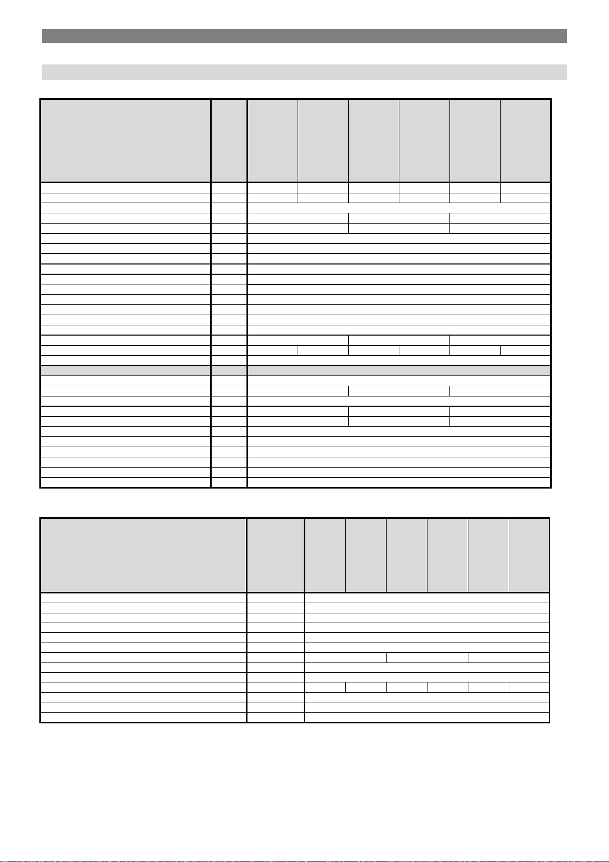
Tab. . 1 Sizes, operation temperature and electrical variables - VIADRUS K4GXH24XX
K4G1H24ZX
K4G1H24PX
K4G2H24ZX
K4G2H24PX
K4G3H24ZX
K4G3H24PX
Fuel type [-] ZP Propane ZP Propane ZP Propane
Category of appliance [-] I
Version C13,C33, C43, C
I3P I
I3P I
I3P
Weight [kg] 26 27.5 26.5
Water volume [l] 2 3 2
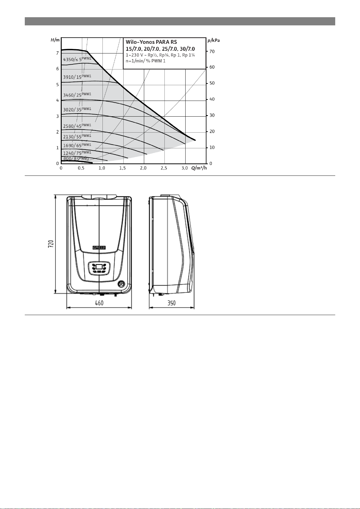
Boiler dimensions – width [mm] 460
– depth [mm] 350
– height [mm] 720
Ø of combustion air connection [mm] 80 / 100 (see fig. no 10)
Ø flue gas socket [mm] 80, 60
Working water overpressure [bar] 3
Testing water overpressure [bar] 5
Pressure loss [-] See diagram 1
Maximum permitted working temperature [°C] 85
Heating water setting range [°C] 25 - 85
Hot water setting range [°C] - 35 - 60 35 - 60
Connecting overpressure of fuel [mbar] 20 37 20 37 20 37
Noise level [dB] < 50
Boiler connection
- heating water output [Js] 3/4“
- heating water input to the heater [Js] - 1/2“ 1/2“
- return heating water input [Js] 3/4“
- return water input from the heater [Js] 1/2“ 3/4“
- system water filling inlet [Js] 1/2" - -
- condensate outlet [mm] Ø 25
- safety valve output [mm] Ø 21,2
- gas inlet [Js] 3/4“
Connecting voltage 1/N/PE 230VAC 50 Hz, TN-S
El. power input including pump [W] 110
El. covering IP 40
Tab. . 2 Thermal – technical parameters - VIADRUS K4GXH24XX
comparison conditions 15 °C and 101.325 kPa, dry gas
K4G1H24ZX
K4G1H24PX
K4G2H24ZX
Boiler output range [kW] 5 - 24
Nominal output 80/60 °C [kW] 22,2
Nominal output 50/30 °C [kW] P=24
Minimum output 50/30 °C [kW] P=5
Maximum nominal heat input [kW] Q=22.8
Minimum nominal heat input [kW] Q=4.6
DHW flow with ∆T [l.min
] - See diagram 2 Boiler efficiency at the nominal output 80/60°C [%] Up to 98
Boiler efficiency at the nominal output 50/30°C [%] Up to 105
Volume flow rate of fuel [m3.h
Mass flow rate of flue gas [kg.h
] 0.5-2.4 0.2-0.9 0.5-2.4 0.2-0.9 0.5-2.4 0.2-0.9
] 8 - 45
Nox class [-] 5
Flue gas temperature (max.) [°C] 85
K4G2H24PX
K4G3H24ZX
K4G3H24PX
4
General Information
2H I2E
2H I2E
2H I2E
53, C83
-
1
-
1
-
1
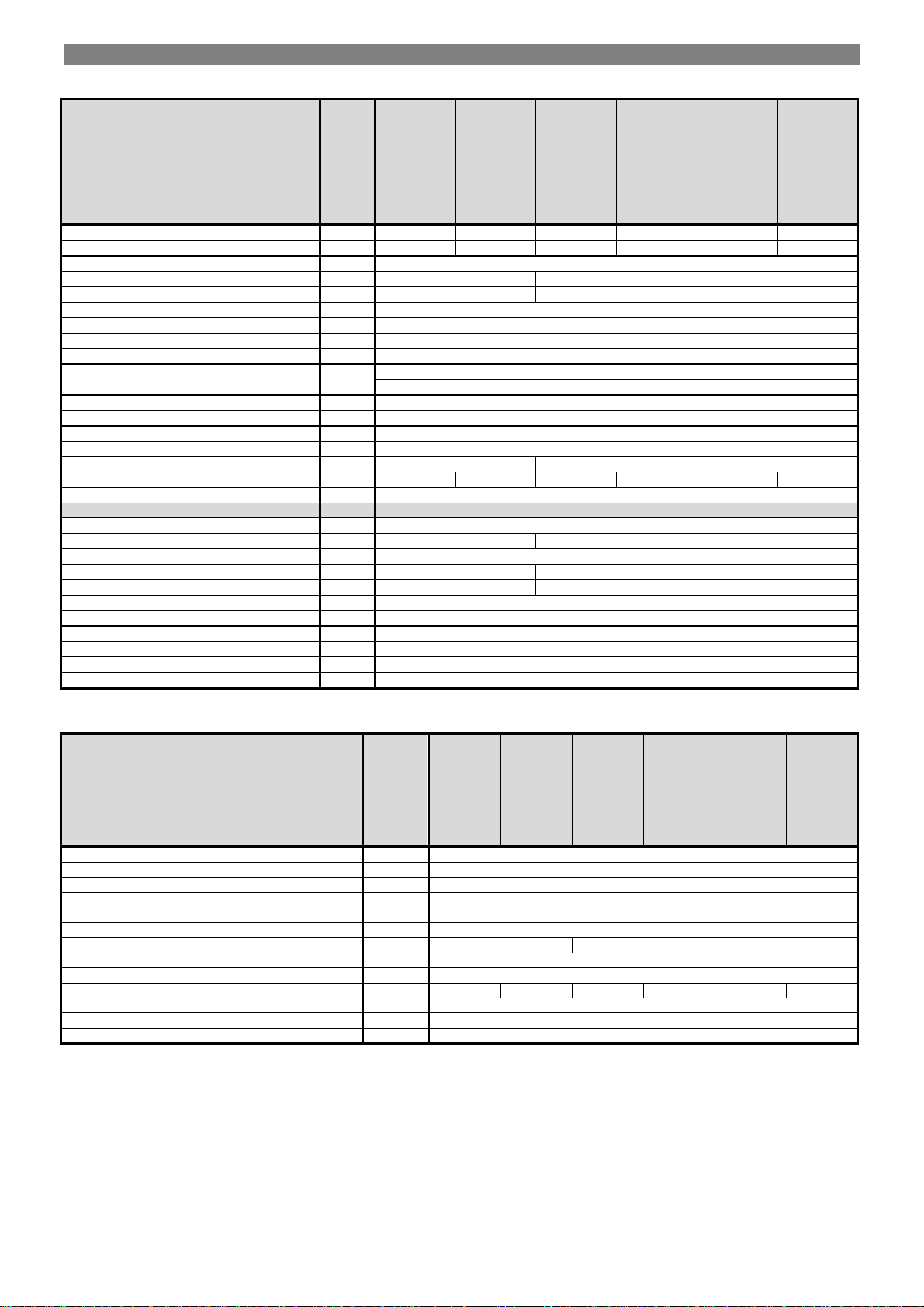
Tab. . 3 Sizes, operation temperature and electrical variables - VIADRUS K4GXH33XX
K4G1H33ZX
K4G1H33PX
K4G2H33ZX
K4G2H33PX
K4G3H33ZX
K4G3H33PX
Fuel type [-] ZP Propane ZP Propane ZP Propane
Category of appliance [-] I
Version C13,C33, C43, C
I3P I
I3P I
I3P
Weight [kg] 28 29,5 28,5
Water volume [l] 3 4 3
Boiler dimensions – width [mm] 460
– depth [mm] 350
– height [mm] 720
Ø of combustion air connection [mm] 80 / 100
Ø flue gas socket [mm] 80, 60 (see fig. no 10)
Working water overpressure [bar] 3
Testing water overpressure [bar] 5
Pressure loss [-] See diagram 1
Maximum permitted working temperature [°C] 85
Heating water setting range [°C] 25 - 85
Hot water setting range [°C] - 35 - 60 35 - 60
Connecting overpressure of fuel [mbar] 20 37 20 37 20 37
Noise level [dB] < 50
Boiler connection
- heating water output [Js] 3/4“
- heating water input to the heater [Js] - 1/2“ 1/2“
- return heating water input [Js] 3/4“
- return water input from the heater [Js] 1/2“ 3/4“
- system water filling inlet [Js] 1/2" - -
- condensate outlet [mm] Ø 25
- safety valve output [mm] Ø 21,2
- gas inlet [Js] 3/4“
Connecting voltage 1/N/PE 230VAC 50 Hz, TN-S
El. power input including pump [W] 110
El. covering IP 40
Tab. . 4 Thermal – technical parameters - VIADRUS K4GXH33XX
comparison conditions 15 °C and 101.325 kPa, dry gas
K4G1H33ZX
K4G1H33PX
K4G2H33ZX
Boiler output range [kW] 6,5 - 33
Nominal output 80/60 °C [kW] P=30,5
Nominal output 50/30 °C [kW] P=33
Minimum output 50/30 °C [kW] P=6,5
Maximum nominal heat input [kW] Q=31,4
Minimum nominal heat input [kW] Q=6,3
DHW flow with ∆T [l.min
] - See diagram 3 Boiler efficiency at the nominal output 80/60°C [%] Up to 98
Boiler efficiency at the nominal output 50/30°C [%] Up to 105
Volume flow rate of fuel [m3.h
Mass flow rate of flue gas [kg.h
] 0,68-3,3 0,28-1,28 0,68-3,3 0,28-1,28 0,68-3,3 0,28-,28
] 11 - 62
Nox class [-] 5
Flue gas temperature (max.) [°C] 85
K4G2H33PX
K4G3H33ZX
K4G3H33PX
5
General Information
Diagram no. 1 A diagram of the boiler heating circuit hydraulic loss
Fig. . 1 The main boiler dimensions
6

General Information
16,50
14,50
12,50
10,50
(kW)
Výkon kotle (kW)
8,50
6,50
4,50
2,50 3,50 4,50 5,50 6,50 7,50 8,50 9,50
24,00
K4G2H24.. Ohřev TV -T 25°C
K4G2H24.. Hot water heating - T 25 °C
Hot water flow rate (l/min)
Průtok TV (l/min)
K4G2H24.. Ohřev TV -
K4G2H24.. Hot water heating - T 30 °C
T=30°C
19,00
14,00
(kW)
Výkon kotle (kW)
9,00
4,00
2,00 3,00 4,00 5,00 6,00 7,00 8,00 9,00 1 0,00 11,00
K4G2H24.. Ohřev TV -T 35°C
K4G2H24.. Hot water heating - T 35 °C
23,00
21,00
19,00
17,00
15,00
(kW)
13,00
Výkon kotle (kW)
11,00
Hot water flow rate (l/min)
Průtok TV (l/min)
9,00
7,00
2,50 3,50 4,50 5,50 6,50 7,50 8,50 9,50
Průtok TV (l/min)
Hot water flow rate (l/min)
Graph No. 2 Dependence of boiler power on flow rate of heated hot water (version VIADRUS K4G2H24XX)
7

General Information
24,00
19,00
(kW)
14,00
Výkon kotle (kW)
9,00
4,00
3,00 5,00 7,00 9,00 11,00 13 ,00 15,00
34,00
K4G2H33.. Ohřev TV -T 35°C
K4G2H33.. Hot water heating - T 25 °C
Hot water flow rate (l/min)
Průtok TV (l/min
K4G2H33.. Ohřev TV -T 30°C
K4G2H33.. Hot water heating - T 30 °C
)
29,00
24,00
(kW)
19,00
Výkon kotle (kW)
14,00
9,00
4,00
2,00 4,00 6,00 8,00 10,00 1 2,00 14 ,00 16 ,00
Hot water flow rate (l/min)
Průtok TV (l/min)
K4G2H33.. Ohřev TV -T 35°C
34,00
29,00
24,00
19,00
(kW)
K4G2H33.. Hot water heating - T 35 °C
Výkon kotle (kW)
14,00
9,00
4,00
3,00 5,00 7,00 9,00 11,00 13,00
Průtok TV (l/min
Hot water flow rate (l/min)
)
Graph No. 3 Dependence of boiler power on flow rate of heated hot water (version VIADRUS K4G2H33XX)
8
General Information
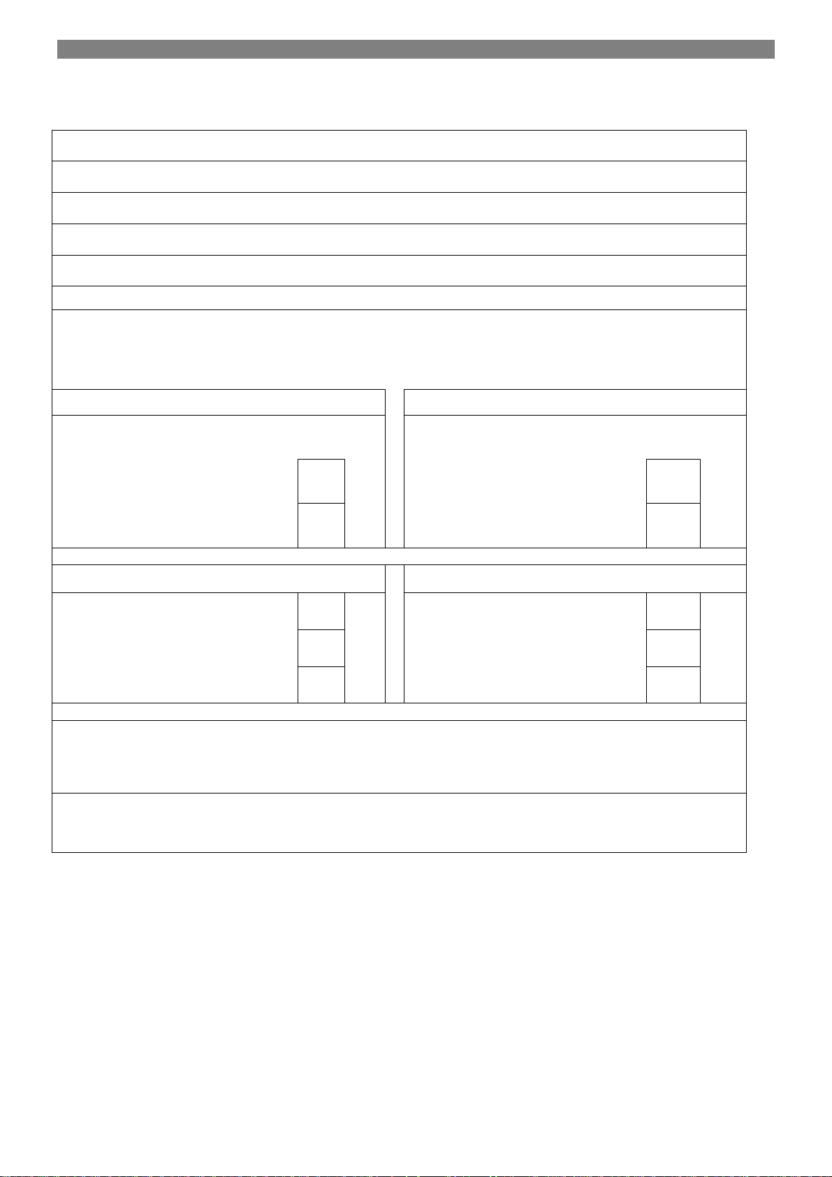
Seasonal space heating energy
Information requirements for boiler space heaters, boiler combination heaters
and cogeneration space heaters
Model(s): VIADRUS K4G1H24XX
Condensing boiler: yes
Low-temperature (**) boiler: no
B1 boiler: no
Cogeneration space heater: no If yes, equipped with a supplementary heater:
Combination heater: no
Rated heat output
Item
Symbol
Prated 24 kW
Value
For boiler space heaters and boiler combination heaters: Useful
heat output
At rated heat output and hightemperature regime (*)
At 30 % of rated heat output and
low-temperature regime (**)
P4 24 kW
P1 4 kW
Unit
efficiency
For boiler space heaters and boiler combination heaters: Useful
efficiency
At rated heat output and hightemperature regime (*)
At 30 % of rated heat output and lowtemperature regime (**)
Item
Symbol
ƞ
90 %
s
ƞ
97,53 %
4
ƞ
105,72 %
1
Value
Auxiliary electricity consumption Other items
At full load el
0,02 kW
max
Standby heat loss P
0,045 kW
stby
At part load el
0,011 kW
min
Ignition burner power consumption P
- kW
ign
In standby mode PSB 0,003 kW
Emissions of nitrogen oxides NOx 25
Contact details
VIADRUS a.s.
Bezručova 300
Bohumín
735 81
Czech Republic
Unit
mg/
kWh
(*) High-temperature regime means 60 °C return temperature at heater inlet and 80 °C feed temperature at heater outlet.
(**) Low temperature means for condensing boilers 30 °C, for low-temperature boilers 37 °C and for other heaters 50 °C return
temperature (at heater inlet).
9
General Information
Seasonal space heating energy
Information requirements for boiler space heaters, boiler combination heaters
and cogeneration space heaters
Model(s): VIADRUS K4G2H24XX
Condensing boiler: yes
Low-temperature (**) boiler: no
B1 boiler: no
Cogeneration space heater: no If yes, equipped with a supplementary heater:
Combination heater: yes
Rated heat output
Item
Symbol
Prated 24 kW
Value
For boiler space heaters and boiler combination heaters: Useful
heat output
At rated heat output and hightemperature regime (*)
At 30 % of rated heat output and
low-temperature regime (**)
P4 24 kW
P1 4 kW
Unit
efficiency
For boiler space heaters and boiler combination heaters: Useful
efficiency
At rated heat output and hightemperature regime (*)
At 30 % of rated heat output and lowtemperature regime (**)
Item
Symbol
ƞ
90 %
s
ƞ
97,53 %
4
ƞ
105,72 %
1
Value
Auxiliary electricity consumption Other items
At full load el
0,02 kW
max
Standby heat loss P
0,045 kW
stby
At part load el
0,011 kW
min
Ignition burner power consumption P
- kW
ign
In standby mode PSB 0,003 kW
Emissions of nitrogen oxides NOx 25
For combination heaters:
Unit
mg/
kWh
Declared load profile
Daily electricity consumption Q
Contact details
(*) High-temperature regime means 60 °C return temperature at heater inlet and 80 °C feed temperature at heater outlet.
(**) Low temperature means for condensing boilers 30 °C, for low-temperature boilers 37 °C and for other heaters 50 °C return
temperature (at heater inlet).
XL Water heating energy efficiency ƞwh 84 %
0,204 kWh
elec
VIADRUS a.s.
Bezručova 300
Bohumín
735 81
Czech Republic
Daily fuel consumption Q
23,215 kWh
fuel
10

General Information
Seasonal space heating energy
Information requirements for boiler space heaters, boiler combination heaters
and cogeneration space heaters
Model(s): VIADRUS K4G3H24XX
Condensing boiler: yes
Low-temperature (**) boiler: no
B1 boiler: no
Cogeneration space heater: no If yes, equipped with a supplementary heater:
Combination heater: yes
Rated heat output
Item
Symbol
Prated 24 kW
Value
For boiler space heaters and boiler combination heaters: Useful
heat output
At rated heat output and hightemperature regime (*)
At 30 % of rated heat output and
low-temperature regime (**)
P4 24 kW
P1 4 kW
Unit
efficiency
For boiler space heaters and boiler combination heaters: Useful
efficiency
At rated heat output and hightemperature regime (*)
At 30 % of rated heat output and lowtemperature regime (**)
Item
Symbol
ƞ
90 %
s
ƞ
97,53 %
4
ƞ
105,72 %
1
Value
Auxiliary electricity consumption Other items
At full load el
0,02 kW
max
Standby heat loss P
0,045 kW
stby
At part load el
0,011 kW
min
Ignition burner power consumption P
- kW
ign
In standby mode PSB 0,003 kW
Emissions of nitrogen oxides NOx 25
For combination heaters:
Unit
mg/
kWh
Declared load profile
Daily electricity consumption Q
Contact details
(*) High-temperature regime means 60 °C return temperature at heater inlet and 80 °C feed temperature at heater outlet.
(**) Low temperature means for condensing boilers 30 °C, for low-temperature boilers 37 °C and for other heaters 50 °C return
temperature (at heater inlet).
XL Water heating energy efficiency ƞwh 81 %
0,222 kWh
elec
VIADRUS a.s.
Bezručova 300
Bohumín
735 81
Czech Republic
Daily fuel consumption Q
24,301 kWh
fuel
11

General Information
Seasonal space h
eating energy
Information requirements for boiler space heaters, boiler combination heaters
and cogeneration space heaters
Model(s): VIADRUS K4G1H33XX
Condensing boiler: yes
Low-temperature (**) boiler: no
B1 boiler: no
Cogeneration space heater: no If yes, equipped with a supplementary heater:
Combination heater: no
Rated heat output
Item
Symbol
Prated 33 kW
Value
For boiler space heaters and boiler combination heaters: Useful
heat output
At rated heat output and hightemperature regime (*)
At 30 % of rated heat output and
low-temperature regime (**)
P4 30,3 kW
P1 6 kW
Unit
efficiency
For boiler space heaters and boiler combination heaters: Useful
efficiency
At rated heat output and hightemperature regime (*)
At 30 % of rated heat output and lowtemperature regime (**)
Item
Symbol
ƞ
90 %
s
ƞ
98,4 %
4
ƞ
104,8 %
1
Value
Auxiliary electricity consumption Other items
At full load el
0,11 kW
max
Standby heat loss P
0,044 kW
stby
At part load el
0,04 kW
min
Ignition burner power consumption P
- kW
ign
In standby mode PSB 0,003 kW
Emissions of nitrogen oxides NOx 26
Contact details
VIADRUS a.s.
Bezručova 300
Bohumín
735 81
Czech Republic
Unit
mg/
kWh
(*) High-temperature regime means 60 °C return temperature at heater inlet and 80 °C feed temperature at heater outlet.
(**) Low temperature means for condensing boilers 30 °C, for low-temperature boilers 37 °C and for other heaters 50 °C return
temperature (at heater inlet).
12

General Information
Seasonal space heating energy
Information requirements for boiler space heaters, boiler combination heaters
and cogeneration space heaters
Model(s): VIADRUS K4G2H33XX
Condensing boiler: yes
Low-temperature (**) boiler: no
B1 boiler: no
Cogeneration space heater: no If yes, equipped with a supplementary heater:
Combination heater: yes
Rated heat output
Item
Symbol
Prated 33 kW
Value
For boiler space heaters and boiler combination heaters: Useful
heat output
At rated heat output and hightemperature regime (*)
At 30 % of rated heat output and
low-temperature regime (**)
P4 30,3 kW
P1 6 kW
Unit
efficiency
For boiler space heaters and boiler combination heaters: Useful
efficiency
At rated heat output and hightemperature regime (*)
At 30 % of rated heat output and lowtemperature regime (**)
Item
Symbol
ƞ
90 %
s
ƞ
98,4 %
4
ƞ
104,8 %
1
Value
Auxiliary electricity consumption Other items
At full load el
0,11 kW
max
Standby heat loss P
0,044 kW
stby
At part load el
0,04 kW
min
Ignition burner power consumption P
- kW
ign
In standby mode PSB 0,003 kW
Emissions of nitrogen oxides NOx 26
For combination heaters:
Unit
mg/
kWh
Declared load profile
Daily electricity consumption Q
Contact details
(*) High-temperature regime means 60 °C return temperature at heater inlet and 80 °C feed temperature at heater outlet.
(**) Low temperature means for condensing boilers 30 °C, for low-temperature boilers 37 °C and for other heaters 50 °C return
temperature (at heater inlet).
XL Water heating energy efficiency ƞwh 86 %
0,180 kWh
elec
VIADRUS a.s.
Bezručova 300
Bohumín
735 81
Czech Republic
Daily fuel consumption Q
22,66 kWh
fuel
13
General Information
Seasonal space heating energy
Information requirements for boiler space heaters, boiler combination heaters
and cogeneration space heaters
Model(s): VIADRUS K4G3H33XX
Condensing boiler: yes
Low-temperature (**) boiler: no
B1 boiler: no
Cogeneration space heater: no If yes, equipped with a supplementary heater:
Combination heater: yes
Rated heat output
Item
Symbol
Prated 33 kW
Value
For boiler space heaters and boiler combination heaters: Useful
heat output
At rated heat output and hightemperature regime (*)
At 30 % of rated heat output and
low-temperature regime (**)
P4 30,3 kW
P1 6 kW
Unit
efficiency
For boiler space heaters and boiler combination heaters: Useful
efficiency
At rated heat output and hightemperature regime (*)
At 30 % of rated heat output and lowtemperature regime (**)
Item
Symbol
ƞ
90 %
s
ƞ
98,4 %
4
ƞ
104,8 %
1
Value
Auxiliary electricity consumption Other items
At full load el
0,11 kW
max
Standby heat loss P
0,044 kW
stby
At part load el
0,04 kW
min
Ignition burner power consumption P
- kW
ign
In standby mode PSB 0,003 kW
Emissions of nitrogen oxides NOx 26
For combination heaters:
Unit
mg/
kWh
Declared load profile
Daily electricity consumption Q
Contact details
(*) High-temperature regime means 60 °C return temperature at heater inlet and 80 °C feed temperature at heater outlet.
(**) Low temperature means for condensing boilers 30 °C, for low-temperature boilers 37 °C and for other heaters 50 °C return
temperature (at heater inlet).
XL Water heating energy efficiency ƞwh 77 %
0,190 kWh
elec
VIADRUS a.s.
Bezručova 300
Bohumín
735 81
Czech Republic
Daily fuel consumption Q
25,742 kWh
fuel
14
General Information
•
4 Boiler Description
4.1 Boiler Design
The boiler elementary structure consists in a condensing exchanger made of stainless steel pipes. It is checked for tightness by test
overpressure 5 bar. The boiler is further equipped with a premix burner. The combustion mixture is mixed in a mixer in the preset air-gas ratio
within the entire output range. Air is supplied to the mixer by a modulation fan.
The boiler is made in three versions:
VIADRUS K4G1HXXXX version designed for heating only is equipped with a circulation pump
VIADRUS K4G2HXXXX version with a circulation pump and flow type hot water (hereafter referred to as “DHW”) heater
VIADRUS K4G3HXXXX version with a circulation pump and a three-way valve ready to be used in combination with a reservoir type hot
The Honeywell automatics is an electronic control and ignition automatics designed for gas-fired central heating boilers with a modulated fan
and burner with preliminary mixing.
The combustion air inlet and the flue gas outlet may be implemented by several means as follows:
-
to the chimney,
-
through the wall,
-
through the roof (either inclined or horizontal),
-
to a joint shaft.
The boiler is an appliance in version C, i.e., a closed appliance with electronic ignition and flame ionization.
water heater
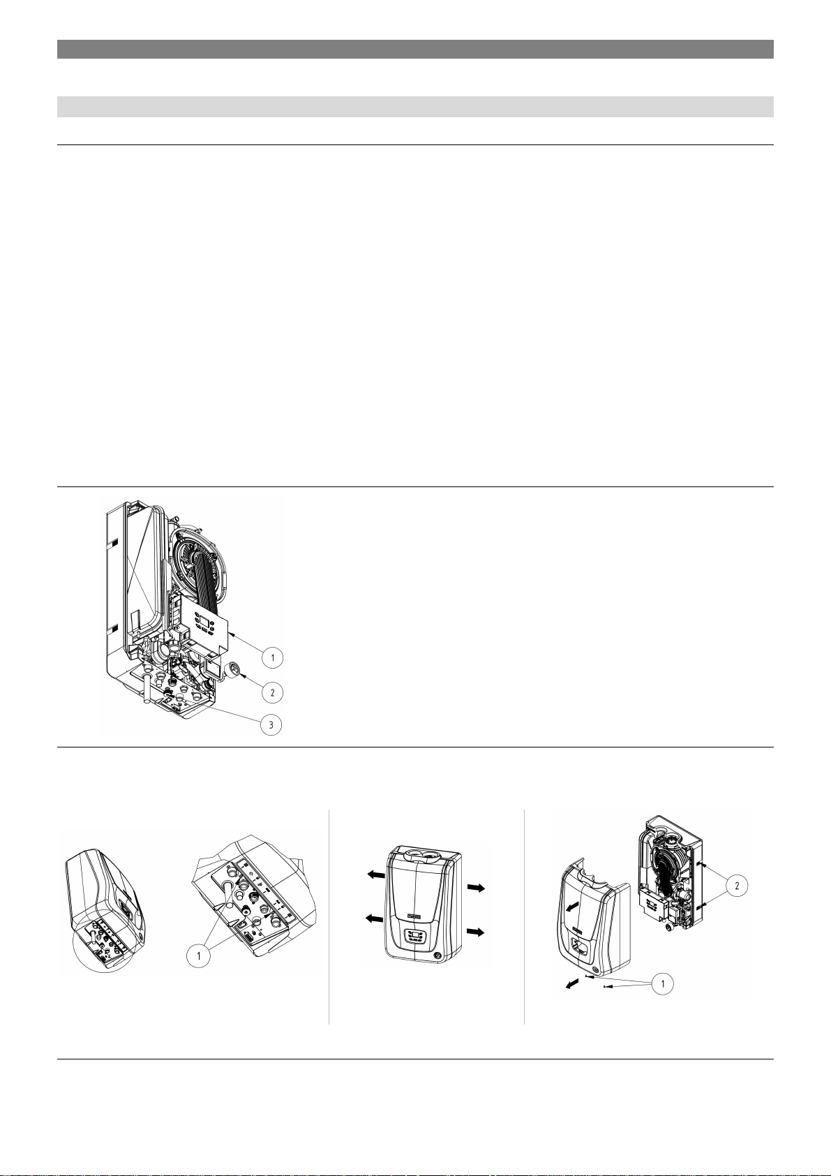
4.2 Control Features
Fig. . 2 The VIADRUS K4 boiler control panel
4.2.1 Removing the front cover
1 electronic panel with the control panel
2 pressure gauge
3 valve for adding water to the heating system
• Remove the front cover
• Remove the bolts (1)
Fig. . 3 Removing the boiler front cover
Pulling the cover side detach
the Velcro strip (2)
15
General Information
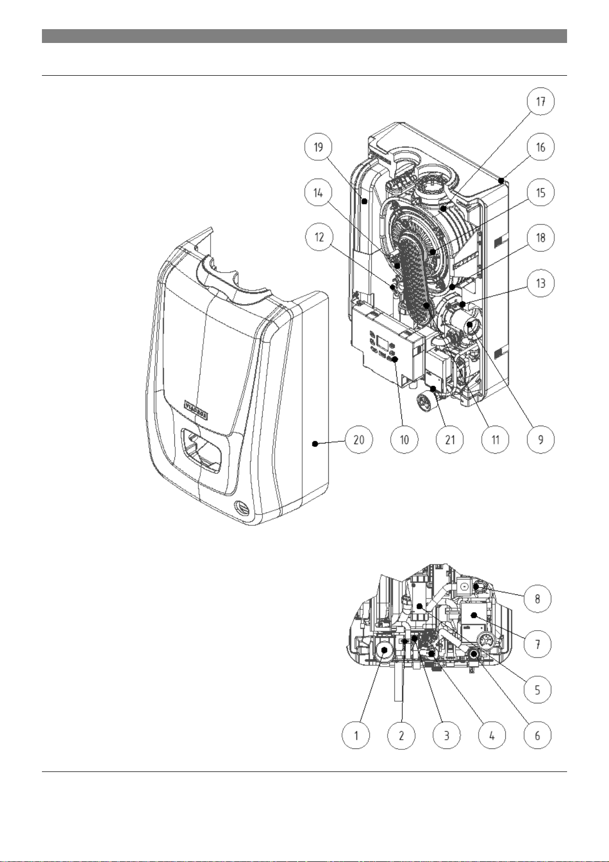
4.3 Main Boiler Parts
1 three-way valve (only for versions K4G2HXXXX and K4G3HXXXX)
2 HSW temperature sensor (only for version K4G2HXXXX)
3 HSW exchanger (only for version K4G2HXXXX)
4 gas valve
5 siphon
6 safety valve
7 circulation pump
8 gas supply pipe
9 bleeder valve
10 boiler electronics
11 burner plate
12 heating water temperature sensor
13 mixer
14 safety thermostat
15 combination electrode
16 boiler frame
17 exchanger
18 fan
19 expansion tank
20 pressure gauge
21 boiler front cover
Fig. . 4 The VIADRUS K4 boiler assembly (version shown - K4G2HXXXX)
16

General Information
1 condensing exchanger
2 input of return water to the exchanger
3 pump
4 input of return water to the pump
5 heating system (radiators)
Fig. . 5 VIADRUS K4G1HXXXX with only water heating for the system
(hydraulic diagram of the version and the sketch of the hydro-block)
1 condensing exchanger
2 input of return water to the exchanger
3 pump
4 input of return water to the pump
5 heating system (radiators)
6 output of hot water from the exchanger
Fig. . 6 VIADRUS K4G2HXXXX with a flow type heater
(hydraulic diagram of the version and the sketch of the hydro-block)
6 output of hot water from the exchanger
7 input of hot water to the radiators
8 filling valve
9 pressure relief valve
7 input of hot water to the radiators
8 three-way valve
9 flow type water heater
10 input of water to the flow type water heater
11 output of water from the flow type water heater
12 pressure relief valve
1 condensing exchanger
2 input of return water to the exchanger
3 pump
4 input of return water to the pump
5 heating system (radiators)
6 output of hot water from the exchanger
7 input of hot water to the radiators
8 three-way valve
Fig. . 7 VIADRUS K4G3HXXXX the boiler version
(hydraulic diagram of the version and the sketch of the hydro-block)
9 filling valve
10 output of hot water from the heater
11 refilling of water to the system
12 reservoir type water heater
13 relief valve of the heater
14 input of water to the heater
15 pressure relief valve
17
 Loading...