

Viadrus HERCULES U 32 Series, HERCULES U32 D, HERCULES U32 B, HERCULES U32 Operation And Installation Manual
HERCULES U 32
Manual for boiler operation and installation
GB_2017_20
GB_2015_46

Content
1
2
3
3.1
3.2
3.3
3.4
4
4.1
4.2
5
5.1
5.2
6
6.1
6.2
7
7.1
7.2
8
9
10 Instructions for the product disposal after its useful life period ................................................................................................................ 18
11 Warranty and liability for defects ............................................................................................................................................................ 19
12 Product fiche .......................................................................................................................................................................................... 20
p.
Boiler Use and Advantages ...................................................................................................................................................................... 3
Technical parameters of the boiler ........................................................................................................................................................... 3
Description ............................................................................................................................................................................................... 5
Boiler Construction............................................................................................................................................................................. 5
Regulation and safety elements ......................................................................................................................................................... 6
Device for removing excess heat ....................................................................................................................................................... 6
Equipment for heat exhausting – accumulating reservoir ................................................................................................................... 8
Location and installation ........................................................................................................................................................................... 8
Regulations and guidelines ................................................................................................................................................................ 8
Placement options ............................................................................................................................................................................. 9
Delivery and installation ......................................................................................................................................................................... 10
Delivery and accessories ................................................................................................................................................................. 10
Installation procedure ....................................................................................................................................................................... 10
5.2.1 Installation of boiler drum ........................................................................................................................................................... 10
5.2.1.1
Installation of boiler drum – after-cooling loop ................................................................................................................... 10
5.2.1.2
Installing the boiler drum – two-way safety valve DBV 1 - 02 ............................................................................................ 11
5.2.1.3
Location of the assembly of ceramic inserts, the secondary air nozzle, the inclined grate (fig. no. 15) .............................. 11
5.2.2 Shell installation ......................................................................................................................................................................... 12
5.2.3 Draught regulator ....................................................................................................................................................................... 14
5.2.4 Cleaning tool mounting .............................................................................................................................................................. 14
5.2.5 Filling the heating system with water .......................................................................................................................................... 14
Putting into operation – instructions for contractual service organization ................................................................................................ 15
Verification activities before start-up ................................................................................................................................................. 15
Putting into operation ....................................................................................................................................................................... 15
Boiler operation by user ......................................................................................................................................................................... 15
Firing ............................................................................................................................................................................................... 16
Operation ......................................................................................................................................................................................... 17
Maintenance .......................................................................................................................................................................................... 17
IMPORTANT NOTICE............................................................................................................................................................................ 18
Number of sections
5 6 7
Number of sections
5 6 7
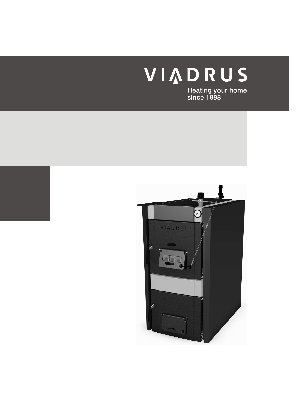
Dear Customer,
Thank you for purchasing a universal boiler HERCULES U 32 and thus showing your confidence in the company VIADRUS a.s.
For the correct way of handling your new boiler, please read the instructions for its use, especially the Chap. no. 7. – Boiler operation by user,
the Chap. no. 8 - Maintenance and the Chap. No. 9 - Important warnings. Please follow further information, ensuring trouble-free boiler
operation to both your and our satisfaction.
The boiler HERCULES U 32 is cast-iron sectional gasification boiler designed to burn:
HERCULES U32 D fuel: hard wood
HERCULES U32 B fuel: lignite
HERCULES U32 fuel: hard coal
Burning of other materials (e.g. plastic) is forbidden.
1 Boiler Use and Advantages
The boiler HERCULES U 32 meets the requirements for heating of houses, shops, etc.
The boiler is manufactured as hot water boiler with natural and forced circulation of hot water and working overpressure up to 400 kPa (4 bar).
Before dispatch it is checked for tightness with the test pressure of 800 kPa (8 bar).
The boiler is designed for heating in both closed and open heating systems.
The Boiler Advantages:
1. High service life of cast iron exchanger and all other parts due to the quality of the materials used.
2. Long-term proven design.
3. Sophisticated manufacturing technology on the automatic forming lines with consistent and approved quality of the production process (ISO
9001, ISO 14 001).
4. Combustion efficiency 86,5 - 90 %.
5. Low fuel consumption.
6. Simple operation and maintenance.
2 Technical parameters of the boiler
Tab. №. 1 Dimensions and technical parameters of the boiler
Combustion chamber volume dm3 32 39 51
Water content l 40,5 46,5
Weight kg 348 410
Combustion chamber depth mm 280 370
Flue socket diameter mm 156 156
Boiler dimensions: – height x width mm 1240 x 683 1240x683
Filling hole dimensions mm 310x236 310 x 236
Maximum water operating pressure kPa (bar) 400 (4) 400 (4)
Minimum water operating pressure kPa (bar) 50 (0,5) 50 (0,5)
Test water overpressure kPa (bar) 800 (8) 800 (8)
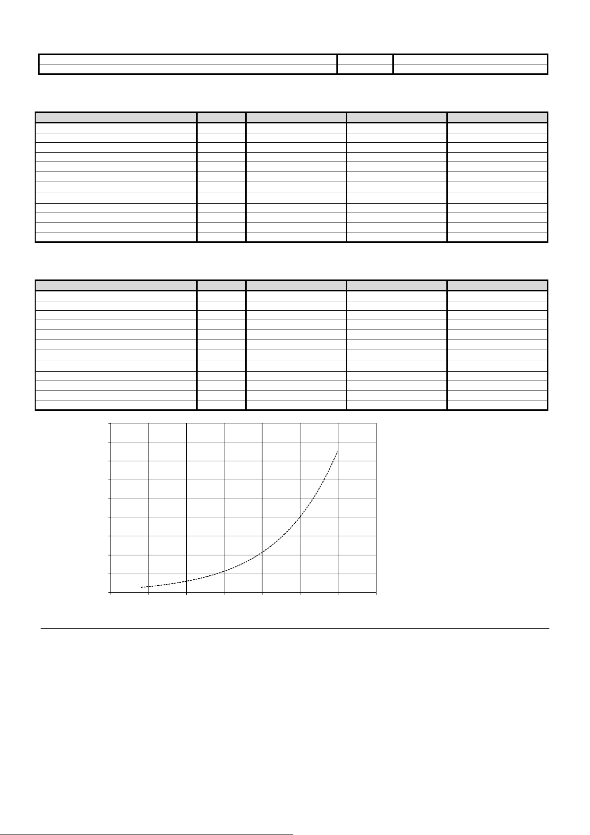
Hydraulic loss - see Fig. 1 see Fig. 1 see Fig. 1
Input water minimum temperature °C 50 50
Heating water recommended operating
temperature
Noise level dB < 65 < 65
Boiler connections: – heating water 2“ 2“
Temperature of cooling water for the device
for removing excess heat
Overpressure of cooling water for the
device for removing excess heat
Tab. №. 2 HERCULES U32 D technical parameters - fuel: hard wood
Boiler class in accordance with EN 303 – 5 - 3 3
Rated power kW 15 19
Fuel consumption kg/h 3,7 4,8
Max. fuel mass in the filling chamber kg 12 14
Flue gas temperature at rated output °C 130 - 170 130 - 170
Flue gas mass flow at rated power kg/sec 0,01 0,0137
Chimney draught
Burning time
Efficiency % 88,9 88,3
Energy efficiency class A+ A+ A+
Energy efficiency index 116 115 114
Season energy efficiency % 79 78 78
– depth L mm 881 992
°C
– return water 2“ 2“
°C 5 – 20 5 – 20 5 – 20
kPa (bar) 200 – 600 (2 - 6) 200 – 600 (2 - 6) 200 – 600 (2 - 6)
fuel moisture max. 20 % calorific power: 14 – 18 MJ. kg
mbar 0,18 0,20 0,22
hours min. 2 min. 2 min. 2
60 – 80 60 – 80
-1
52,5
472
480
156
1240x683
1103
310 x 236
400 (4)
50 (0,5)
800 (8)
50
60 – 80
< 65
2“
2“
3
22
5,5
16
130 - 170
0,015
88,0
3
Number of sections
5 6 7
Number of sections
5 6 7
Tab. №. 3 Recommended dimensions of wood blocks
Block diameter mm Ø 40 to 120
Block length mm 350
Tab. №. 4 HERCULES U32 B technical parameters - fuel: lignite
grain size 20 - 40 mm, fuel moisture max. 15 %
calorific power: 14 – 20 MJ.kg-1
Boiler class in accordance with EN 303 – 5 - 5 4
Rated power kW 14 19
Fuel consumption kg/h 2,3 3,2
Max. fuel mass in the filling chamber kg 18 21
Flue gas temperature at rated output °C 130-170 130 - 170
Flue gas mass flow at rated power kg/sec 0,008 0,0112
Chimney draught
Burning time
mbar 0,18 0,23 0,25
hours min. 4 min. 4 min. 4
Efficiency % 89,9 86,5
5
21
3,5
25
130 - 170
0,0123
90,1
Energy efficiency class B C B
Energy efficiency index 82 79 82
Season energy efficiency % 82 79 82
Tab. №. 5 HERCULES U32 technical parameters - fuel: hard coal
grain size 20 - 40 mm, fuel moisture max. 15 %
calorific power: 26 - 29 MJ.kg-1
Boiler class in accordance with EN 303 – 5 - 5 5
Rated power kW 15 21
Fuel consumption kg/h 2,1 3,1
Max. fuel mass in the filling chamber kg 18 21
Flue gas temperature at rated output °C 130-170 130 - 170
Flue gas mass flow at rated power kg/sec 0,008 0,0127
Chimney draught
Burning time
mbar 0,18 0,23 0,25
hours min. 4 min. 4 min. 4
Efficiency % 89,6 88,6
5
25
3,5
25
130 - 170
0,0133
89,4
Energy efficiency class C C C
Energy efficiency index 83 82 82
Season energy efficiency % 83 82 82
1800
1600
1400
pz (Pa)
1200
1000
800
600
400
200
0
0 0,5 1 1,5 2 2,5 3 3,5
Fig. №. 1 Hydraulic loss of the boiler drum
Qz (10-3m3.s-1)
4
Number of sections
- 5 6 7
Lenght A mm 881 991 1103
Lenght B mm 659 730 841
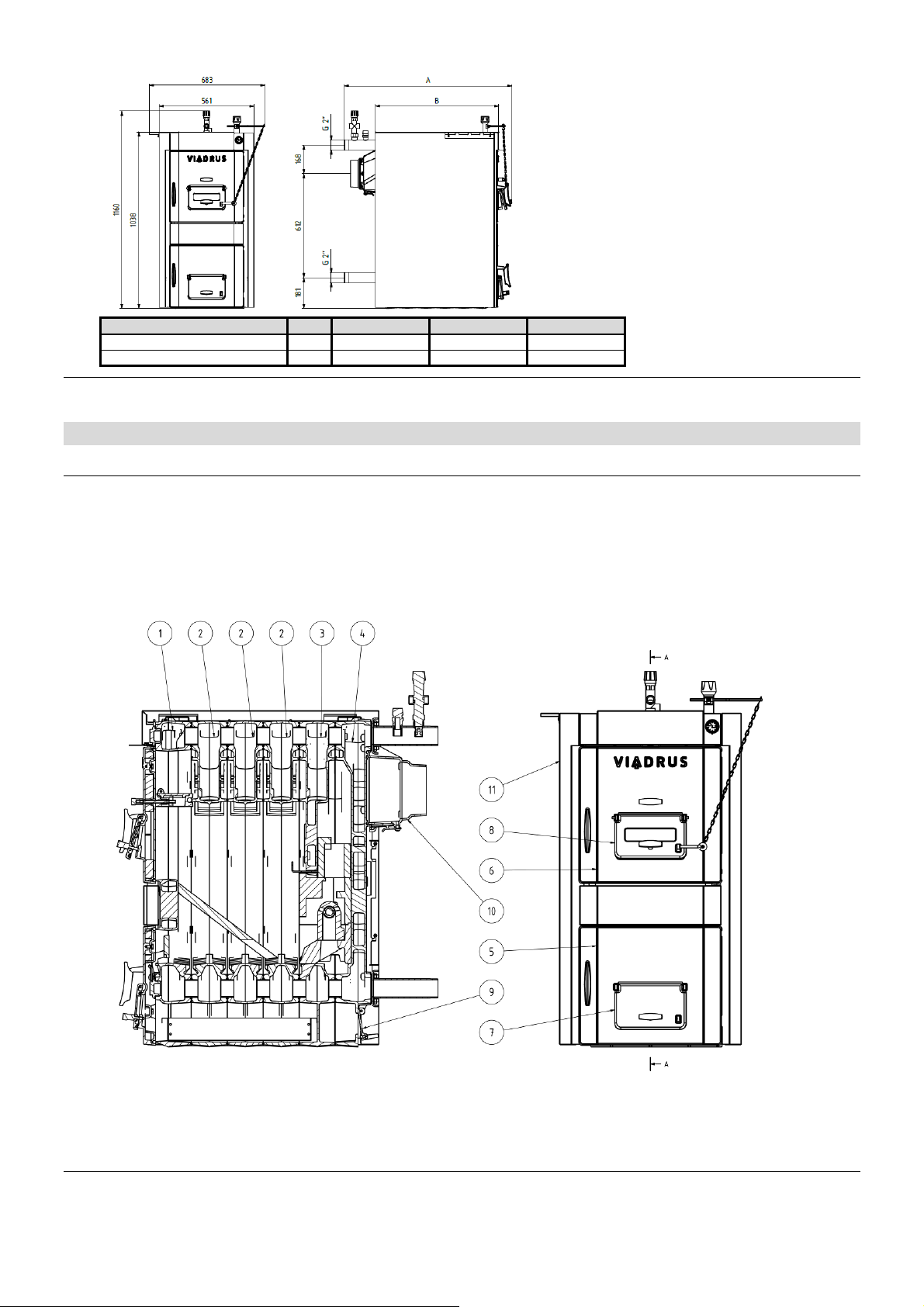
Fig. №. 2 Connection dimensions of boiler HERCULES U 32
3 Description
3.1 Boiler Construction
The main part of the boiler is cast iron sectional boiler drum made of grey cast iron according to EN 1561, quality 150.
Pressure parts of boiler correspond to strength requirements according to EN 303-5.
The boiler drum is assembled of sections by means of pressed boiler inserts with 56 mm diameter and secured by anchor bolts. Sections create
the feed space, combustion and ash space, water space and convective part of the boiler. Input and output of heating water is located in the
rear of the boiler.
Rear boiler section has the smoke adapter and heating water flange at its top, and the return water flange at the bottom. The stoking and ash
door are mounted to the front section. Inclined grate is placed to the filling space. The whole boiler drum is insulated by using a harmless
mineral insulation which reduces losses by sharing heat into the surroundings. The high-quality komaxit spray is used for boiler shell colour
treatment.
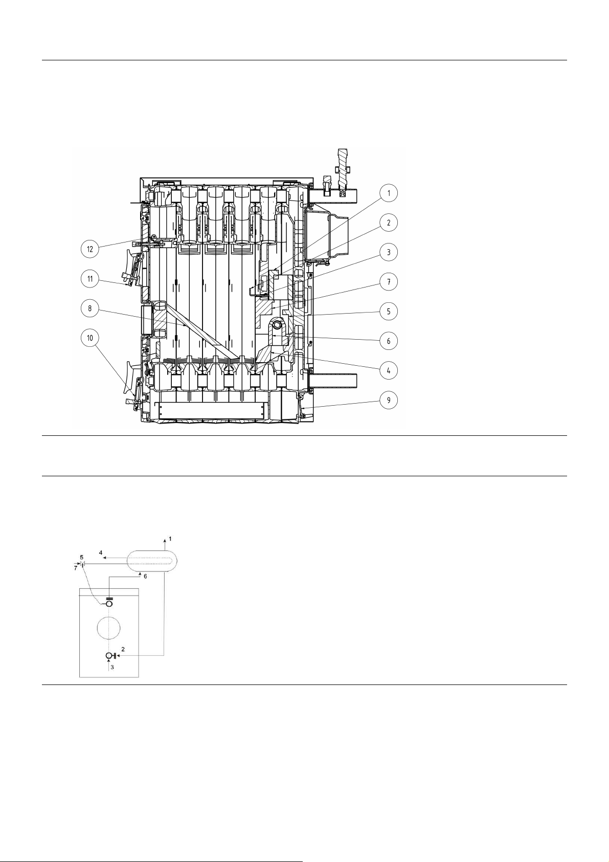
1. Front section
2. Middle section
3. Penultimate section
4. Rear section
5. Ash door
6. Stoking door
Fig. №. 3 Main part of the boiler
7. Ash door choker
8. Stoking door choker
9. Rear choker
10. Smoke adapter
11. Shell
5
3.2 Regulation and safety elements
Stoking door choker regulates the supply of primary combustion air above the fuel. It is operated by the draught regulator or manually by the
setting screw of the choker.
The ash door choker regulates the supply of secondary combustion air under the boiler grate. It is operated manually by the setting screw of the
choker.
For the tertiary air inlet, the choker in the lower rear part of the boiler is used. It is controlled with help of an adjusting screw, but it is adjusted to
the ideal position in the production plant.
For detecting the heating water temperature and water pressure in the heating system, the associated device - thermomanometer is used.
Thermomanometer sensor well is located in the upper part of the front boiler section.
1. Upper ceramic liner
2. Locking pin for the upper lining
3. Hole for the locking pin
4. Lower ceramic liner
5. Middle ceramic liner - rear part
6. Tertiary air inlet nozzle
7. Middle ceramic liner - front
part
8. Inclined grate
9. Tertiary air choker
10. Secondary air choker
11. Primary air choker
12. Shorting flap
Fig. №. 4 Assembly of the boiler HERCULES U 32
3.3 Device for removing excess heat
After-cooling loop or two-way safety valve DBV 1 - 02 serve to remove excess heat in the event that the water temperature in the
boiler exceeds 95 °C. After-cooling loop is connected to the flange of the boiler according to Fig. 5, two-way safety valve according to
Fig. 7).
In case of the boiler overheating (outlet water temperature is higher than 95 °C), thermostatic valve switches and the excess heat is removed by
the after-cooling loop.
1. Heating water outlet into the system 2”
2. Return water inlet from the after-cooling loop 1 1/2 “
3. Return water inlet to the boiler from the system 2”
4. Cooling water outlet
5. Thermostatic valve TS 130 (STS 20)
6. Heating water outlet from the boiler 2”
Fig. №. 5 Hydraulic diagram of after- cooling loop connection
If the system is equipped with the two-way safety valve DBV 1 - 02 and the boiler becomes overheated (outlet water temperature is higher than
95 ° C), the two-way safety valve creates cold water circuit until the time the temperature drops below the limit temperature. At this moment, the
discharge cooling equipment and the cold water inlet for the system refilling are simultaneously closed.
7. Cooling water inlet
6
A - cold water inlet
B - output to the boiler
C - output to the drain
D - input from the boiler
Fig. №. 6 Two way safety valve DBV 1 - 02
In the system, it is necessary to install a safety valve with max. overpressure of 400 kPa (4 bar), which dimensions must correspond
to the boiler nominal output. The safety valve must be installed immediately behind the boiler. Shut-off valve must be installed
between the safety valve and the boiler. For further questions please contact our contractual installation companies and service
organizations.
Specifications of the two-way safety valve DBV 1 - 02 (from Regulus)
Opening temperature (limit): 100 °C (+0° - 5 °C)
Maximum temperature: 120 °C
Maximum pressure on the boiler side: 400 kPa (4 bar)
The maximum pressure on the water side: 600 kPa (6 bar)
Nominal flow at p 100 kPa (1 bar): 1.9 m3/h
Use
Two-way safety valve DBV 1 - 02 is designed for central heating boilers protection against overheating. In the valve drum, the discharge and
refill valves are controlled by thermostatic element. When achieving the limit temperature the discharge and refill valve open simultaneously,
which means that cold water flows into the boiler while hot water is drained from the boiler. When the temperature drops below the limit, the
discharge and filling valves are closed simultaneously.
ATTENTION! Do not replace the safety valve.
In case of reaction of the two-way safety valve, when there could be refilled water that does not conform to CSN 07 7401, it is
necessary to adjust water in the system so that it again conforms to this standard.
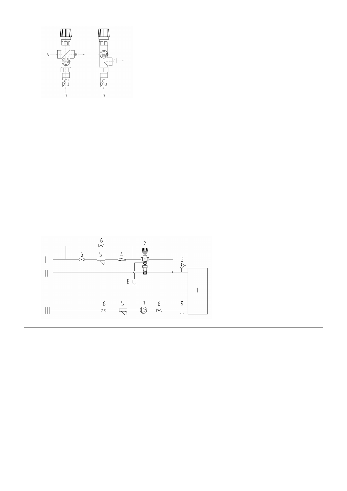
1. Boiler
2. Two-way safety valve DBV 1 - 02
3. Safety valve
4. Reducing valve
5. Filter
6. Ball valve
7. Pump
8. Excess heat removal
9. Discharge valve
I – Cold water inlet
II – Heating water outlet
III – Return water inlet
Fig. №. 7 Recommended diagram of the two-way safety valve DBV 1 - 02 connection
Installation
Installation may only be performed by a qualified person. For proper operation of the thermostatic two-way safety valve it is necessary to comply
with the prescribed conditions for its installation and respect the flow directions indicated on its body. The safety valve is always mounted in the
output pipe of the boiler or directly on the boiler in its upper part where the heated water leaves boiler and is transported into the heating system.
When installing the valve, it is necessary to check whether the use of the 3/4“ socket, which can be both in the pipeline and on the boiler,
ensures complete immersion of the valve thermostatic element after the valve installation. After mounting into the socket, at the point "C" (Fig.
6), the discharge pipe is connected through which the hot water from the boiler will flow to drain. At the point "A" (Fig. 6), the supply of cooling
water is connected (Fig. 7), which ensures cooling the boiler down after the valve putting into operation. At the cooling water inlet, a filter to
remove mechanical impurities must be installed. At the point "B" (Fig. 6) there is connected the pipeline, which according to Fig. 7 leads to the
return line of the heating system near the boiler.
Regular maintenance
1x per year, turn the safety valve head to remove possible contaminants seated in it. Clean the filter at the cooling water inlet.
In case of using an open expansion tank, the safety device against overheating is not necessary.
Every heat source in an open heating system must be connected with the open expansion tank positioned located at the highest point of the
heating system. The expansion tanks must be designed to accommodate changes in water volume resulting from heating and cooling.
The open expansion tanks must be equipped with non-closable vent and overflow pipes. The overflow pipe must be designed to safely drain the
maximum flow volume entering the system. This can be achieved by rating the overflow pipes by one DN higher than the filling pipe. The
expansion tanks and their connecting pipes must be designed and positioned so as to reliably prevent them from freezing.
7

Recommended values
1. Heat source
2. Expansion tank
3. Safety valve
4. Expansion pipe
5. Overflow pipe
6. Filling pipe
7. Water level limiter
8. Return pipe
Fig. №. 8 Examples of the open expansion tanks connection
3.4 Equipment for heat exhausting – accumulating reservoir
The boiler has to be operated with an accumulating reservoir.
Calculation of the smallest capacity of the accumulating heat exchanger,
Vsp = 15Tb x QN (1-0,3 x (QH/Q
min
))
where:
Vsp accumulating reservoir capacity in liters
QN nominal heat power in kW
Tb combustion time in hours
QH buildings’ heat load in kW
Q
smallest heat power in kW
min
The sizes of the accumulating reservoir have to be determined on the basis of the boiler power and the used fuel. The biggest capacity has to
taken into consideration, whereas the minimum used capacity of the reservoir has to be 300 l.
In case that the reservoir is fully charged, it is necessary to shut down the boiler and heat up by heat from the accumulating reservoir. After the
heat is spent in the reservoir, put the boiler into operation again. The accumulating reservoir enables provision of heat comfort and at the same
time the boiler operation.
ATTENTION! Failure of it will cause extreme pollution of the boiler drum.
Hydraulic schemes of the boilers with an accumulating reservoir are at disposal in the project materials of Viadrus at www.viadrus.cz.
4 Location and installation
4.1 Regulations and guidelines
The solid fuel boiler may be installed by a company holding a valid certification for its installation and maintenance. For the installation, a project
must be elaborated in accordance with applicable regulations. Before the boiler installation to an older heating system, the installation company
must flush (clean) the whole system. The heating system must be filled with water that meets the requirements of CSN 07 7401 and
especially its hardness must not exceed the required parameters.
Tab. №. 6
Hardness mmol/l 1
Ca2+ mmol/l 0.3
concentration of total Fe + Mn mg/l (0.3)*
*) recommended value
ATTENTION!!! The manufacturer does not recommend to use antifreeze.
In case of reaction of the two-way safety valve, when there could be refilled water that does not conform to CSN 077401, it is
necessary to adjust water in the system so that it again conforms to this standard.
a) to the heating system
CSN 06 0310 Heating systems in buildings – Design and installation.
CSN 06 0830 Heating systems in buildings – Safety devices.
CSN 07 7401 Water and steam for thermal energy equipments with working pressure up to 8 MPa.
EN 303-5 Boilers for central heating – Part 5: Boilers for central heating for solid fuels, manually and automatically
b) on the chimney
CSN 73 4201 Chimneys and flues – Design, implementation and connection of fuel consumers.
c) regarding the fire regulations
CSN 06 1008 Fire safety of heat installations.
EN 13501-1 + A1 Fire classification of construction products and building structures – Part 1: Classification using data from
d) to the system for the HW heating
CSN 06 0320 Heating systems in buildings - Hot water preparation - Design and projection.
CSN 06 0830 Heating systems in buildings – Safety devices.
CSN 75 5409 Internal water piping.
stocked, with nominal heat output of up to 500 kW – Terminology, requirements, testing and marking.
reaction to fire tests.
8
Number of sections
- 5 6 7
Examples of building materials and products classified to the fire reaction class
A1
A2
B
C (D)
E (F)
4.2 Placement options
Placement of the boilers in living areas (including halls) is prohibited!
Steady supply of air for combustion and ventilation must be ensured to the room where the boiler is installed.
When installing and using the boiler, all requirements of CSN 06 1008 must be complied with.
Boilers in the central heating system have to be connected to a separate venting unit. The chimney with a correct draught is the basic
presumption for correct function of the boiler. It influence both the boiler power and its effectiveness. A flue-gas ducting from the
boiler to the venting unit has to be as short as possible, preferably without elbows with a slope from the boiler upwards. The chimney
has to have a prescribed draught (according to the boiler size – see the manual). It has to be well-tightened and insulated to avoid
condensation of water vapor and tar.
Placement of the boiler regarding the fire regulations:
When installing the boiler, we recommend to use original cast iron basement (see Fig. 10) supplied by the manufacturer. When installing the
boiler without the basement, it is necessary to comply with the conditions set out in the point 1.
1. Placement on the floor made of incombustible material (Fig. 9):
− place the boiler on a fireproof base exceeding the boiler dimensions only by the boiler drum depth and on the sides by 20 mm;
− if the boiler is installed in a cellar, we recommend to install it on a substructure at least 50 mm high;
− the boiler must be placed in the centre of the basement.
2. Safe distance from flammable materials
− when installing and operating the boiler it is necessary to keep the safe distance of 200 mm from flammable materials with combustibility
grade A1, A2, B and C (D);
− for easily flammable materials with combustibility grade E (F), which burn quickly and by themselves also after the ignition source
removal (e.g. paper, cardboard, asphalt and tar boards, wood and fibreboards, plastics, flooring materials), the safe distance is doubled,
that is 400 mm;
− the safe distance is to be doubled also when the fire reaction class is not proven.
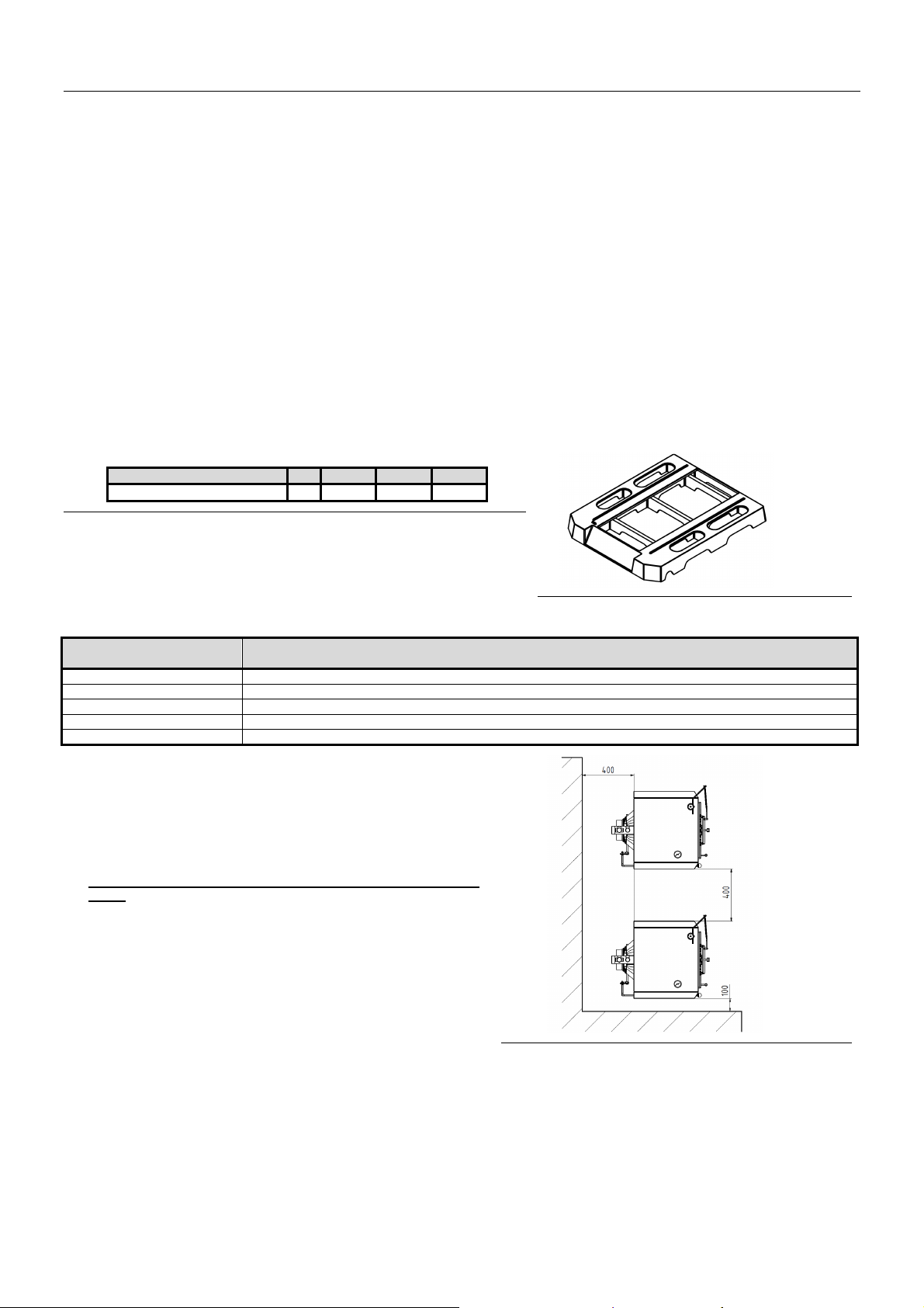
Lenght L
mm 659 728 841
Fig. №. 9 Substructure dimensions
Tab. №. 7 Fire reaction class
Fire reaction class
– incombustible
– combustible with difficulty
– hardly combustible
– medium combustible
– easily combustible
granite, sandstone, concrete, bricks, ceramic tiles, mortars, fire plasters, ...
acumin, izumin, heraklith, lignos, boards and basalt felt, fibreglass boards, ...
beech and oak wood, hobrex boards, plywood, werzalit, gypsum plasterboard , sirkolit,...
pinewood, larch, whitewood, chipboard and cork boards, rubber flooring,...
asphalt board, fibreboards, cellulose materials, polyurethane, polystyrene, polyethylene, PVC,…
(a choice from EN 13501-1+A1)
Boiler positioning with regard to the necessary handling space:
− basic environment AA5/AB5 according to ČSN 33 2000-1 ed. 2;
− min. 1000 mm handling space must be left in front of the boiler;
− minimum distance between the boiler rear side and wall is 400 mm;
− at least from one side part, keep the access area to the rear boiler part
of 400 mm.
Placing of fuel:
− dry fuel has to be used in order to ensure its proper burning in the
boiler. Fuel stored in cellar or at least sheltered is recommended by the
manufacturer;
− it is prohibited to store the fuel behind the boiler or next to the boiler in
the distance shorter than 400 mm;
− it is prohibited to store the fuel between two boilers in the boiler room;
− the manufacturer recommends to keep the distance between the boiler
and the fuel min. 1000 mm or store the fuel in a different room than the
boiler is installed.
Fig. №. 10 Cast iron basement of the boiler
Fig. №. 11 Boilers positioning in boiler room
9

5 Delivery and installation
5.1 Delivery and accessories
The boiler is supplied according to the order so that the complete boiler drum is placed on the palette. The boiler shell is packed separately.
Accessories are stored inside the boiler drum, accessible by opening the stoking door. The boiler is packed in a shipping container and must not
be tilted during transport.
Standard boiler delivery:
• Boiler on the palette
- heating water flange with thread 2 pc
- return water flange with a distribution pipe 1 pc - only for 7 sect. version
- sealing φ 90 x 60 x 3 2 pc
- washer 10.5 8 pc
- nut M10 8 pc
- fill and drain tap Js 1/2“ 1 pc
- complete draught regulator 1 pc
- blind plug Js 6/4“ 1 pc
- sealing φ 60 x 48 x 2 1 pc
- capillary spring 1 pc
- wave spring 1 pc
• lining of the combustion changer
- lower ceramic liner (box 4) 1 pc
- middle ceramic liner - rear part (box 3) 1 pc
- middle ceramic liner - front part (box 5) 1 pc
- upper ceramic liner (box 6) 1 pc
- tertiary air inlet nozzle (box 2) 1 pc
• pin for the upper lining or Allen wrench 4 1 pc
• inclined grate 1 pc
• shell including insulation and ash-pan
- reduced bracket 2 pc
- washer 10.5 4 pc
- nut M10 4 pc
- spring clamp 4 pc
- screw M5 x 12 10 pc
- connecting pin 4 pc
- thermomanometer 1 pc
- screw M8 x 12 4 pc
• cleaning tools
- hook 1 pc
- brush with handle 1pc
- spike 1 pc
- cleaning tool holder 1pc
• handling key 1pc
• refractory adhesive 50 ml to back the nozzle 1pc
• sales and technical documentation
Additional equipment (not included into the delivery):
• Cast iron boiler basement 5 sections (ord. code 17659)
• Cast iron boiler basement 6 sections (ord. code 17751)
• Cast iron boiler basement 7 sections (ord. code 18569)
Necessary accessories (not included into the delivery):
• After-cooling loop (1 pc) inlc. the flange of the two-way safety valve DBV 1 - 02 incl. siseal (10 g).
This equipment may not be used in case of open heating system.
• Thermostatic valve TS 130 (STS 20) – TV 95°C – can be bought in warehouses (only in case of delivery with the after-cooling loop)
• Safety valve 1 pc
At the customer's request (not included into the delivery):
• Filter 3/4“ (for the boiler with the two-way safety valve DBV 1 - 02)
The boiler equipment ordered as "additional equipment, necessary accessories and at the customer's request" is not included in the
basic price of the boiler.
5.2 Installation procedure
5.2.1 Installation of boiler drum
5.2.1.1 Installation of boiler drum – after-cooling loop
1. Set the boiler drum on the basement or substructure.
2. Pre-weld the heating water flange of the after-cooling loop on the after-cooling loop weldment (according to the boiler room dispositions),
insert the seating Ø 90 x 60 x 3 between the flange and the boiler, then mount the weldment by means of 4 nuts M 10 and 4 washers 10.5
to the boiler. Connect the upper heating water outlet and the heating system by welding.
3. Connect the lower outlet from the after-cooling loop to the boiler by welding the 1 1/2“ pipe to the outlet of the return water (return water
flange).
10
 Loading...