

Viadrus HERCULES U28 Operation And Installation Manual

VIADRUS HERCULES U28
M
anual for boiler operation and installation
GB_2015_21
GB_2016_48

2
Table of contents
page
1 Technical information ............................................................................................................................................ 3
1.1 Usage ............................................................................................................................................................. 3
1.2 Boiler advantages ........................................................................................................................................... 3
1.3 Boiler technical data ....................................................................................................................................... 4
1.4 Basic boiler dimensions .................................................................................................................................. 5
2 Assembly manual .................................................................................................................................................. 7
2.1 Boiler construction .......................................................................................................................................... 7
2.2 Rules and directives ....................................................................................................................................... 7
2.3 Positioning possibilities .................................................................................................................................. 8
2.4 Delivery and accessories ............................................................................................................................. 10
2.5 Assembly technique ..................................................................................................................................... 12
2.5.1 Installation of the boiler body ................................................................................................................ 12
2.5.2 Mounting of Covers ............................................................................................................................... 12
2.5.3 Way of Positioning of Side Grate in Boiler ............................................................................................ 16
2.5.4 Change of Opening Direction of Stocking Door .................................................................................... 18
2.5.5 Assembly tools for brush ....................................................................................................................... 18
2.5.6 Filling the heating system with water .................................................................................................... 19
2.6 Boiler commissioning ................................................................................................................................... 19
2.6.1 Verification activities before commissioning ......................................................................................... 19
2.6.2 Boiler commissioning ............................................................................................................................ 19
2.7 Control and safety elements ........................................................................................................................ 19
2.8 Equipment for surplus heat withdrawal ........................................................................................................ 21
2.9 Equipment for heat exhausting – accumulating reservoir ............................................................................ 23
3 Manual for operation ............................................................................................................................................ 23
3.1 Boiler operation by user ............................................................................................................................... 23
3.2 Firing ............................................................................................................................................................. 24
3.3 Operation ...................................................................................................................................................... 25
3.4 Boiler cleaning - maintenance ...................................................................................................................... 26
3.5 IMPORTANT NOTICE .................................................................................................................................. 27
4 Instruction for product disposal after its service life ............................................................................................ 28
5 Guarantee and the liability for defects ................................................................................................................. 29
3
Dear customer,
we thank you that you have bought VIADRUS HERCULES U28 universal boiler, thus having shown your
confidence in VIADRUS a.s.
For you to get used to a correct way of handling your new product from the beginning please read at first this
manual for its usage (first of all the chapter no. 3.1 – Boiler operation by user, chapter no. 3.4 – Boiler cleaning maintenance and chapter no. 3.5 – IMPORTANT NOTICE). Please follow the stated information whereby a longlife
and trouble-free boiler operation will be guaranteed for both your and our satisfaction.
1 Technical information
VIADRUS HERCULES U28 is cast-iron low-pressure boiler designed for combustion of solid fuels – light coal and
hard coal. As a complement fuel it is possible to use wood.
Combustion of other materials, like plastics is impermissible.
1.1 Usage
The VIADRUS HERCULES U28 boiler complies with the requirements on heating up family houses, shops,
schools etc.
The boiler is manufactured as a hot-water boiler with both natural and forced heating water circulation and working
overpressure up to 400 kPa (4 bar). Before dispatch the boiler is tested for tightness by applying
800 kPa (8 bar) testing overpressure.
The boiler is designed for heating both closed and open heating systems.
1.2 Boiler advantages
1. Long lifetime of the cast-iron heat exchange and all other parts with regard to the quality of used materials.
2. Long-term verified construction.
3. Sophisticated manufacturing technology on the automatic forming lines with a constant and verified quality of
the manufacturing process (ISO 9001, ISO 14 001).
4. Combustion efficiency 82 %.
5. Easy operation and maintenance.
6. Output graduation according to the sections number.
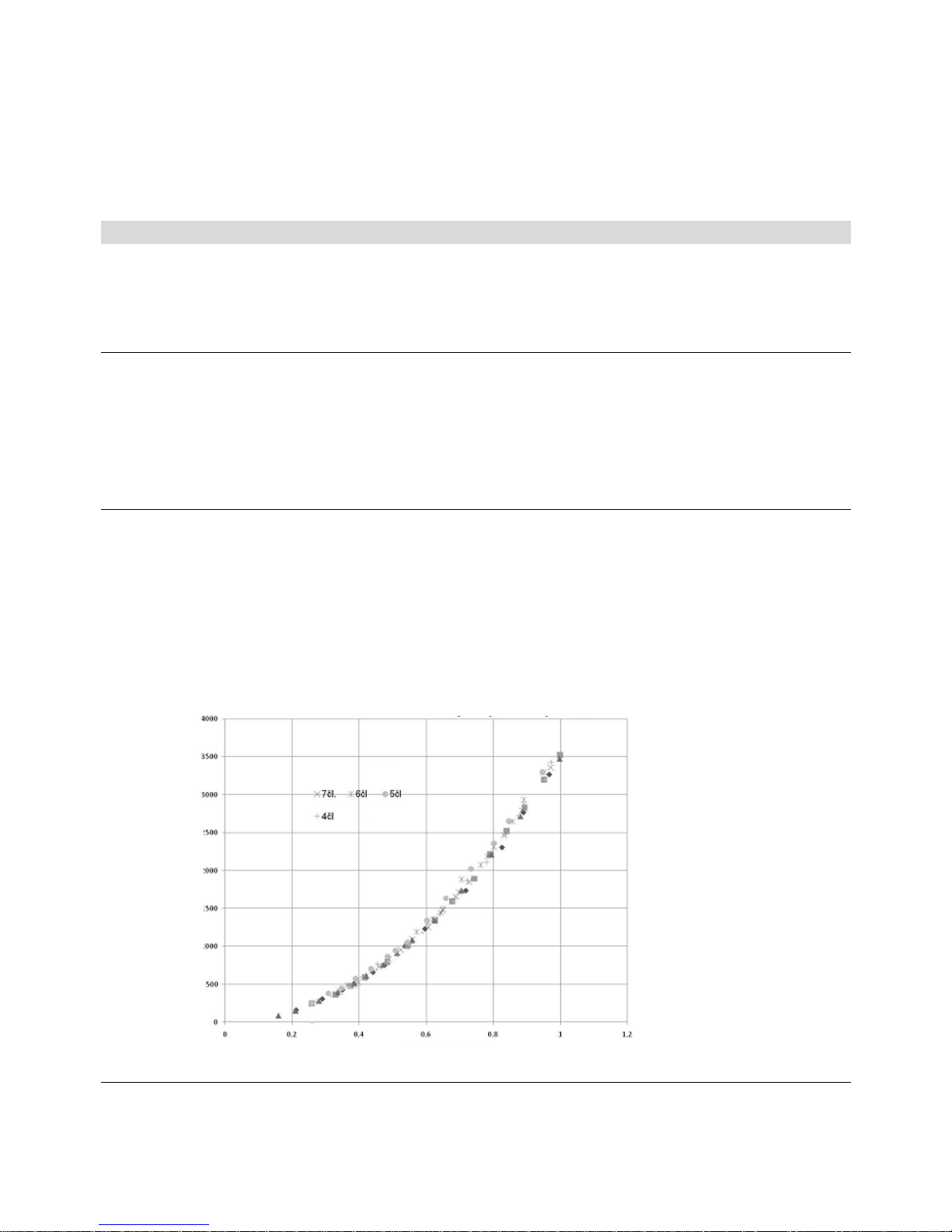
Fig. №. 1 Hydraulic loss of boiler drum
Pressure loss independence on p
z
–
Q flow rate
Flow rate Q (10
-
3 m3.s-
1
)
Pressure loss Pz (Pa)
Čl. = sections

4
1.3 Boiler technical data
Tab. №. 1 Dimensions, technical data
Number of section
s pc 4 5 6 7
Boiler class according to EN 303 - 5 - 3
Combustion chamber volume l 45,6 61,9 78,2 94,9
Water space volume l 52,6 62 71,7 81,3
Weight kg 364 437 510 583
Combustion chamber depth mm 311 422 533 644
Diameter of smoke socket mm 156
Boiler dimensions: height x width mm 1165 x 695
depth L mm 831 942 1053 1164
Filling opening dimensions mm 318 x 265
Maximum working water overpressure kPa
(bar)
400
(4)
Minimum working water overpressure kPa
(bar)
50
(0,5)
Testing water overpressure kPa
(bar)
800
(8)
Boiler hydraulic loss - See Fig. no. 1
Minimum output water temperature °C 60
Control range of water temperature °C 60 – 85
Noise level
dB Does not exceed the level 65 dB (A)
Boiler connections – heating water “ 1 1/2
– return water “ 1 1/2
Cooling water temperature for equipment for
surplus heat withdaral
°C 5 – 20
Cooling water overpressure for equipment
for surplus heat withdaral
kPa
(bar)
200 – 600
(2 - 6)
Tab. №. 2 Technical data – hard coal as fuel
Granularity 20 – 40 mm, fuel moisture max. 15 %
Calorific value of fuel: 14 – 20 MJ.kg-1
Number of sections
pc 4 5 6 7
Nominal heat output kW 19 25 30 35
Fuel consumption at nominal heat output kg.h
-
1
3,7 4,7 5,8 6,8
Fuel efficiency MJ.kg
-
1
19,68
Burning time at nominal output hour 4
Flue gases temperature at nominal heat
output
°C 232 – 288
Flue gases mass flow rate at nominal output kg.s
-
1
0,0156 0,0205 0,0254 0,0303
Efficiency % 80 79 79,5 78,5
Required chimney draught mbar 0,16 0,2 0,25 0,30
Tab. №. 3 Technical parameters – hard coal as fuel
Granularity 20 – 40 mm, fuel moisture max. 15 %
Calorific value of fuel: 26 - 29 MJ.kg
-1
Number of sections
pc 4 5 6 7
Nominal heat output kW 20 27 35 44
Fuel consumption at nominal heat output kg.h
-
1
3,15 4,2 5,4 6,5
Fuel efficiency MJ.kg
-
1
24,2
Burning time at nominal output hour 4
Flue gases temperature at nominal heat
output
°C 243 – 295
Flue gases mass flow rate at nominal output kg.s
-
1
0,0196 0,0251 0,0306 0,0361
Efficiency % 78,4 79,5 81 82,8
Required chimney draught mbar 0,2 0,23 0,27 0,3

5
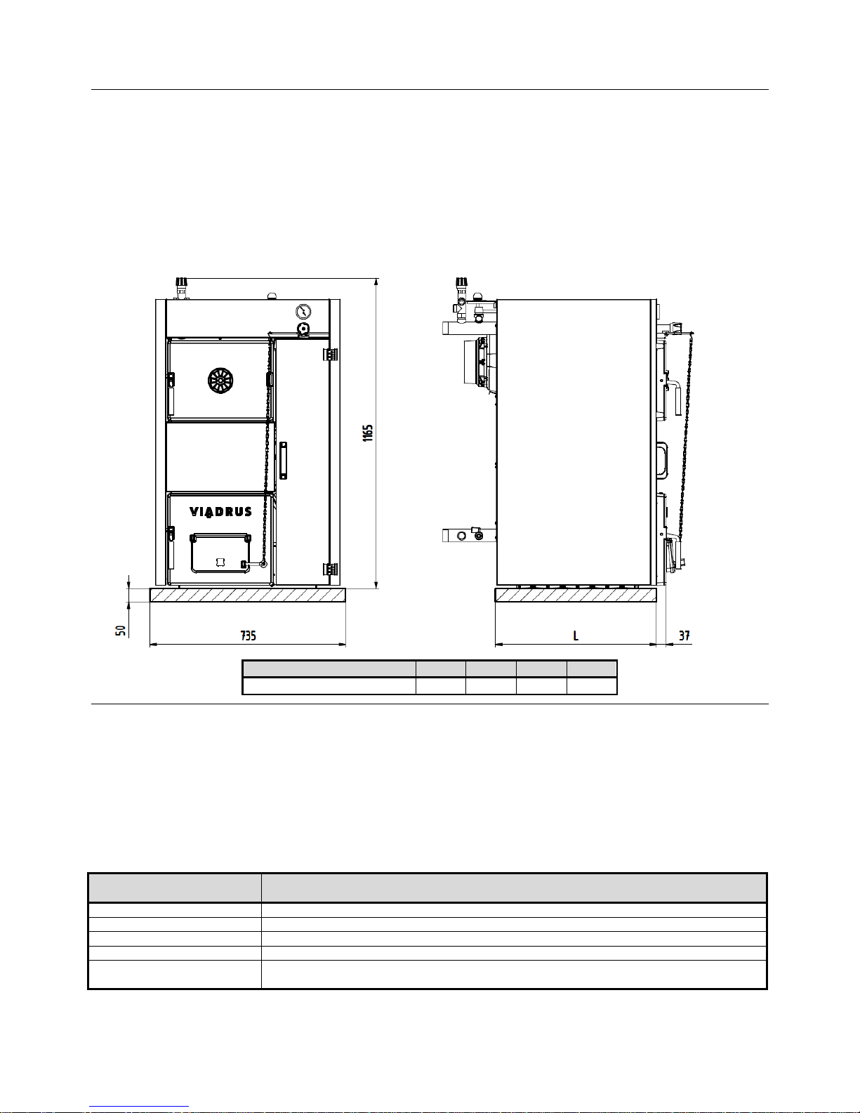
1.4 Basic boiler dimensions
4 5 6 7
L
mm 492 603 714 825
L1
mm 831 942 1053 1164
D
mm 156
Fig. №. 2 Basic boiler dimensions
6
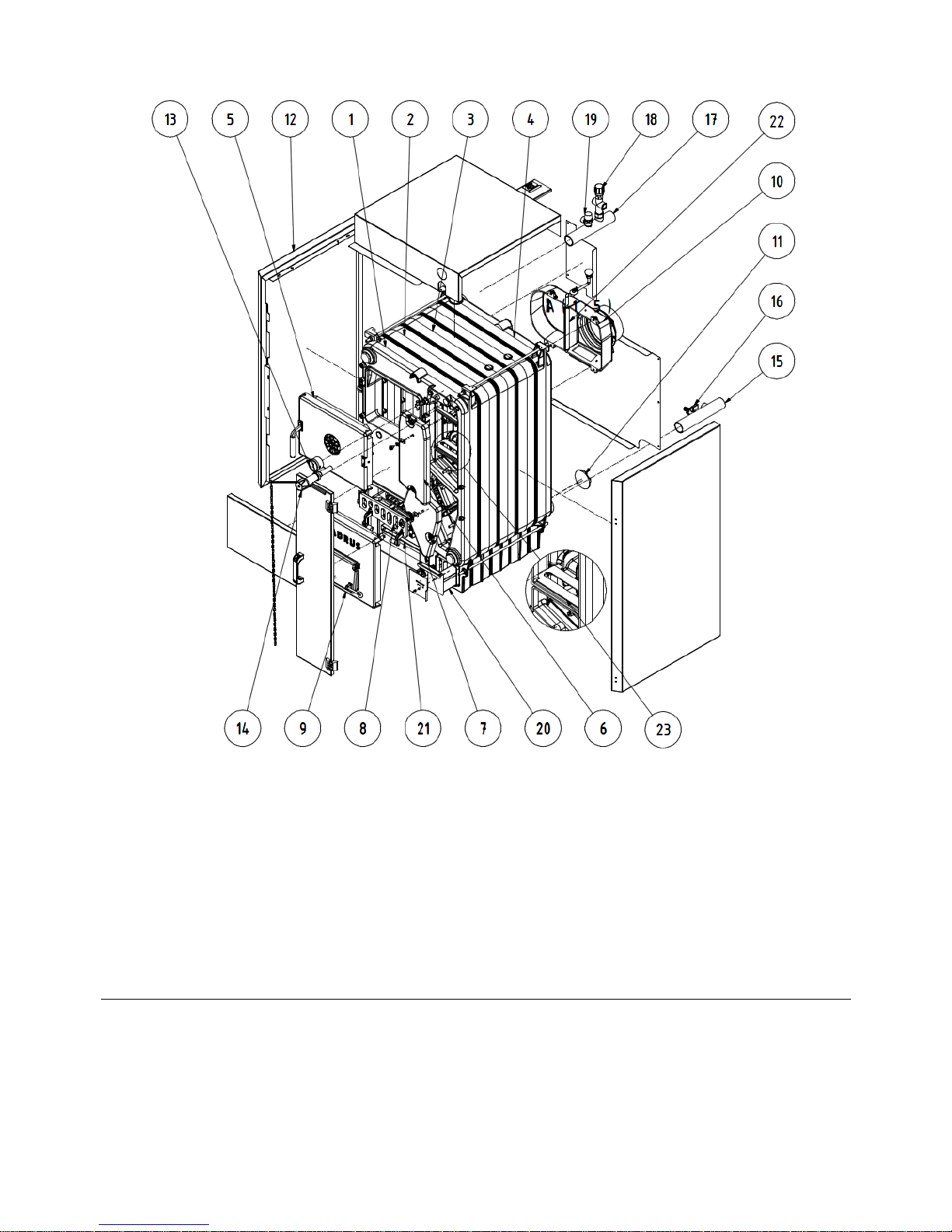
1 Front cell
2 Center cell
3 Middle section without lower bar
4 Rear cell
5 Feeding gate (with the rosette of primary air)
6 Cleaning cover -upper
7 Cleaning cover - lower
8 Dump grate
9 Ash gate (with a suffocating throttle of secondary air)
10 Smoke extension piece
11 Air rosette (tertiary air)
12 Boiler case (complete)
13 Thermo-manometer
14 Draught regulator
15 Pipe of output water
16 Filling and cock
17 Pipe of input water
18 Two-way safety cock DBV 1 - 02
19 Safety valve
20 Small ash pan with a movable cover
(tertiary air)
21 Ash pan
22 Partition of the smoke adapter
23 Partition of the flue gases area
Fig. №. 3 Basic boiler parts
7
2 Assembly manual
2.1 Boiler construction
The main boiler part is the cast-iron sectional boiler drum made of the grey cast-iron according to EN 1561,
quality 150.
The pressure parts meet the strenght demands according to EN 303- 5.
The boiler drum is assembled of sections by means of pressed boiler nipples with 56 mm diameter and secured by
anchor bolts. The boiler sections create the feed space, combustion and ash space, water space and convectional
space. The heating water input and output is situated at the rear boiler part.
There is placed the smoke adapter and heating water connection at the upper part of rear boiler section and the
return water connection at the bottom part. The water connection is possible to connect by means of thread pipes.
The stoking door, ash door and 2 cleaning covers are connected to the front boiler section. Under the ash pan door
there is installed the tilting grate.
The whole boiler drum is insulated by the health harmless mineral insulation, which reduces the losses caused by
heat transmission into the environment. The boiler sell is coloured by a good quality comaxit spray.
2.2 Rules and directives
The solid fuel boiler can be installed by the company holding a valid certification for its installation and
maintenance. There must be made lay-out according to the valid rules for the boiler installation. Before the boiler
installation to the older heating system the installation company must make the flush (cleaning) of the whole
heating system. The heating system must be filled with water meeting the requirements ČSN 07 7401,
especially its hardness must not exceed the required parameters.
Tab. №. 4
Recommended values
hardness mmol/l 1
Ca2+ mmol/l 0,3
Concentration of whole Fe + Mn mg/l (0,3)*
*) recommended value
WARNING!!! The use of anti-freeze mixture is not recommended by the manufacturer.
In case of two way safety vent reaction, when there is a possibility of boiler having been filled with the
water, which does not meet the ČSN 077401 requirements it is necessary to change the water in the
heating system so that it meets the ČSN 077401 requirements again.
a) to the heating system
ČSN 06 0310 Heating systems in buildings – Designing and installation
ČSN 06 0830 Heating systems in buildings – protecting device
ČSN 07 7401 Water and steam for thermal energy equipments with working pressure up to 8 MPa.
EN 303-5 Boilers for central heating – Part 5: Solid fuel boilers for central heating with manual or
automatic feed and max. 500 kW nominal thermal output: terminology, requirements,
testing and marking.
b) to the chimney
ČSN 73 4201 Chimneys and flue gas ducting– designing, implementation and connection of fuel
consumers.
c) regarding the fire regulations
ČSN 06 1008 Fire safety of heat installations.
EN 13501-1 +A1 Fire classification of construction products and building elements – Part 1: Classification
using test data from reaction to fire tests
d) to the system of HWS heating
ČSN 06 0320 Heating systems in buildings – Hot water preparation – Designing and planning
ČSN 06 0830 Heating systems in buildings – Safety devices.
ČSN 75 5409 Water installations inside buildings.
8
2.3 Positioning possibilities
Boiler positioning in the living space (including corridors) is prohibited!
The installation of the boiler must comply with all requirements of ČSN 06 1008.
Permanent access of air must be ensured in the room where the boiler will be installed and operated.
Boiler positioning with regard to the fire regulations:
1. The boiler can be installed on a fire-proof floor (Fig. no. 4):
− Place the boiler on fire-proof base exceeding the boiler platform by 20 mm on sides and only up to the
boiler drum depth.
− If the boiler is positioned in a cellar, we recommend installing it on a retaining wall minimum 50 mm hight.
− Install the boiler in the middle of the retaining wall.
Quantity
of sections
4 5 6 7
L [mm]
494 605 716 827
Fig. №. 4 Boiler base dimensions
2. A safe distance from the combustible materials:
− when installing and operating the boiler it is necessary to keep a safety distance of 200 mm from the
materials of combustibility grade A1, A2, B and C (D);
− for easily combustible materials of combustibility grade E (F), which quickly burn and burn themselves even
after removal of ignition source (such as paper, cardboard, asphalt and tar paper, wood and wood-fiber
boards, plastics, floor coverings) the safe distance has to be doubled, i.e. to 400 mm;
− safe distance should be doubled as bulb where the grade of reaction to fire has not been proved.
Tab. №. 5 Grade of reaction to fire
Grade of reaction to fire
Examples of building materials and pro
ducts included in the reaction to fire
(Extract from EN 13501-1 + A1)
A1
– incombustible
Granite, sandstone, concrete, bricks, ceramic tiles, mortars, fireproof plasters, …
A2
– combustible with difficulty
acumin, izumin, heraklit, lignos, boards and basalt felt, fibreglass boards,...
B
– hardly combustible
Beech and oak wood, hobrex boards, plywood, werzalit, umakart, sirkolit,...
C (D)
– medium combustible
Pinewood, larch, whitewood, chipboard and cork boards, rubber flooring,...
E (F) – easily combustible
Asphaltboard, fibreboards, cellulose materials, polyurethane, polystyrene, polyethylene,
PVC,…

9
Boiler positioning with regard to the necessary handling space:
• Basic environment AA5/AB5 according to ČSN 33 2000-1 ed. 2.
• In front of the boiler there must be left a minimum handling area of 1000 mm.
• The minimum distance between the rear part of boiler and the wall 400 mm.
• At least from one side part keep the access area to the back boiler part of minimum 400 mm.
• Minimal distance from the wall at the left side of boiler is 100 mm. In a case of modification with left opening of
the door, the distance from the wall must be bigger because of door opening in sufficient action range.
Fig. №. 5 Modifications of stocking door opening
Fuel positioning:
• It is interdicted to store the fuel behind the boiler or next to the boiler within a distance smaller than 400 mm.
• It is interdicted to store the fuel between two boilers in the boiler-room.
• The producer recommends to keep the distance between the boiler and fuel min. 1000 mm or to store the fuel
in a different room that where the boiler is installed.
The selection of the right boiler size
The selection of the right boiler size, it means the
heating output, is very important condition for
economic operation and the right boiler function. The
boiler must be selected so that the heating output
conforms to the heating loss of the object. The
nominal output of the boiler is counted according to
the valid rules for outside temperature –12 °C, -15 °C
and –18 °C. The boiler selection with too high heating
output (overrating) results in tarring and ratting of
boiler. It is not useful to use the boiler with higher
output than the heating loss of the boject.
Chimney draught
The chimney with the right chimney draught is the
fundamental prerequisite for the right boiler function. It
influences the boiler output as well as its efficiency.
The boiler can be connected to the venting unit with
the sufficient chimney draught, see. Chapter no. 1.3.
and if the revision by the certified organization is
made.
Fig. №. 6 Positioning of Boilers in Boiler
Room

10
2.4 Delivery and accessories
The boiler is packed in a transport package and must not be tilted over during the transport. The accessories are
put inside the boiler drum, accessible by opening the stoking door.
Standard Boiler Delivery:
•
Boiler with appropriate number of sections on a pallete
•
Cover with insulation including an ash pan, a bracket of cleaning tools – type 2, cover of a movable and small
ash pan of the appropriate size
•
Heating and return water tubes G 1 1/2" 2 pcs
•
Side grate -4 sections 4 sections - 1 pc, 6 sections - 1 pc
•
Side grate -5 sections 5 sections - 1 pc, 7 sections - 1 pc
•
Side grate -additional 6 sections - 1 pc, 7 sections - 1 pc
•
Cleaning tools - handle 1 pc
•
A packet
•
A production label
•
Commercial and technical documents
Packet Accessories:
•
Door hinges 2 pcs
•
A handle 503a - 514 1 pc
•
A magnetic element - flat 1 pc
•
Brush 1 pc
•
Stabbler 1 pc
•
Jointing material for covers:
- Butterfly nut M4 1 pc
- Nut M5 1 pc
- Nut M6 2 pc
- Nut M8 1 pc
- Washers 4,3 9 pcs
- Washers 5,3 4 pcs
- Washers 6,4 2 pcs
- Large-area washers 6,4 2 pcs
- Washers 8,4 2 pcs
- Connecting pins 8 pcs
- Screws M4 x 6 9 pcs
- Screws M5 x10 6 pcs
- Screws M6 x 35 2 pcs
- Screws M8 x 12 1 pcs
- Screws ST 4,8 x 13 11 pcs
- Spring leave retainers 8 pcs
•
A pull rod of smoke control 1 pc
•
Jointing material for the pull rod of smoke control:
- Cotter pins 2,5 x 20 2 pcs
- A nut M10 1 pc
- Washers 10,5 2 pcs
- A plastic ball M10 1 pc
•
A thermomanometer 1 pc
•
A screw of suffocating throttle 1 pc
•
A special hook 1 pc
•
A socket spanner with a handle, hexagonal 902-13 1 pc
•
Filling and discharging cock Js 1/2“ 1 pc
•
Draught regulator - complete 1 pc
•
Plug Js 1 1/2“- blind 1 pc
•
Under plug sealing 1 pc
•
Stick-on label – position of a partition of smoke extension 1 pc
•
Screws M5x10 2 pc
•
Nust M10 5 pc
•
Washers 10,5 6 pc
•
Washers 5,3 2 pc
 Loading...