

Viadrus HERCULES U 22 Operation And Installation Manual

VIADRUS HERCULES U 22 P/N
M
anual for boiler operation and installation
GB_2014_36

2
Table of contents:
page
1. Manufactured boiler variants ......................................................................................................................3
2. Boiler use and advantages ........................................................................................................................3
3. Technical data of boilers ............................................................................................................................4
4. Description .................................................................................................................................................5
4.1 Boiler construction ..............................................................................................................................5
4.2 Control, safety and regulation elements .............................................................................................7
4.3 Boilers wiring diagrams ......................................................................................................................7
5. Positioning and installation ........................................................................................................................9
5.1 Regulations and quidelines ................................................................................................................9
5.2 Positioning possibilities ................................................................................................................... 10
6. Delivery and assembly ............................................................................................................................ 12
6.1 Delivery and accessories ................................................................................................................ 12
6.2 Assembly procedure ........................................................................................................................ 13
7. Commissioning........................................................................................................................................ 16
7.1 Verification before commissioning................................................................................................... 16
7.2 Boilers commissioning ..................................................................................................................... 16
7.3 Boiler conversion from “gaseous or liquid fuels“ to the „solid fuels“ and vice versa ....................... 16
8. Boiler operation by the user .................................................................................................................... 17
9. Maintenance ............................................................................................................................................ 18
10. Defects and their elimination ............................................................................................................... 18
11. IMPORTANT WARNINGS ................................................................................................................... 19
12. Instructions for product disposal after its service life ........................................................................... 20
13. Guarantee and liability for defects ....................................................................................................... 20
3
Dear customer,
We thank you that you have bought the VIADRUS HERCULES U 22 universal boiler thus having
shown your confidence in VIADRUS a.s.
For you to get used to a correct way of handling your new product from the beginning please read at
first this manual for its usage (first of all the chapter no. 8 – Boiler operation by user, chapter no. 9 –
Maintenance and chapter no. 11 – Important warnings). Please follow the undermentioned
information and especially those regarding the prescribed annual controls to be done by an
authorized specialised firm, whereby a long-time and trouble-free boiler operation will be guaranteed
to both your and our satisfaction.
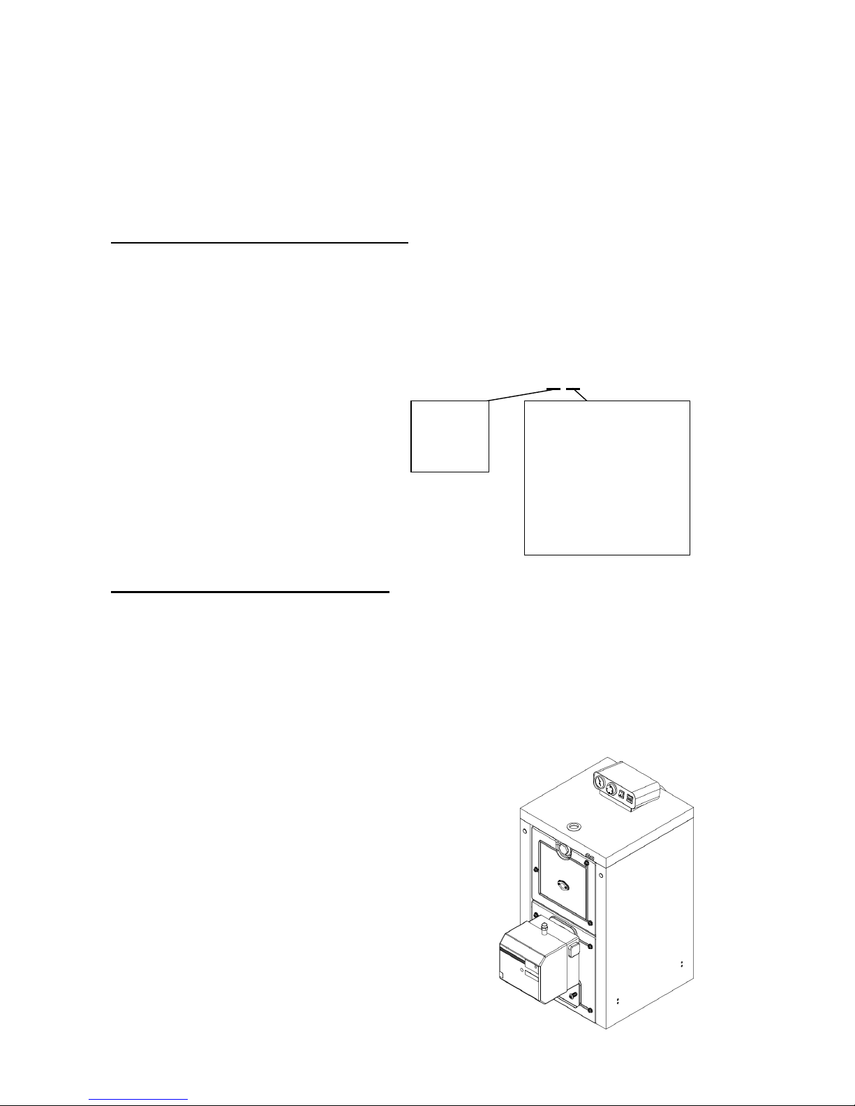
1. Manufactured boiler variants
VIADRUS HERCULES U 22 boiler is a universal cast-iron sectional low-pressure boiler designated for
combustion of:
- Gaseous fuels (natural gas) and its brand name is VIADRUS HERCULES U 22 P
- Liquid fuels (fuel oil extra light – TOEL) and its brand name is VIADRUS HERCULES U 22 N
In the purchase order you must specify the following data:
Purchase order specification code
VIADRUS HERCULES U 22 X X
2. Boiler use and advantages
The boiler design you have received is designated for combustion of gaseous fuels and its brand name is
VIADRUS HERCULES U 22 P and for combustion of liquids fuels and its brand name is VIADRUS
HERCULES U 22 N. The three-sectional size is suitable for heat sources reconstruction in smaller houses
and leisure amenities. Bigger sizes comply with demands on heating the houses, shops, schools etc.
The boiler is only made as a warm-water unit with natural and forced heating water circulation and working
overpressure up to 400 kPa (4 bar). Before despatch the boiler is tested for tightness by applying 800 kPa
(8 bar) test pressure; it stands the insulation and contact resistance tests.
Boiler advantages:
1. A long service life of cast-iron exchanger and
all other parts with regard to the quality of
used materials.
2. Efficiency of gas combustion 89 %.
3. The reliability of regulation and security
elements.
4. Simple operation and maintenance.
5. Low demand on chimney draught..
6. Graduation of output by the number of
sections.
7. Possibility to convert the solid fuels boiler to
gaseous or liquid fuels boilers or vice-versa.
Fuel:
P: gas
N: oil
Number of sections
:
3: 3 sectional design
4: 4 sectional design
5: 5 sectional design
6: 6 sectional design
7: 7 sectional design
8: 8 sectional design
9: 9 sectional design
0: 10 sectional design
4
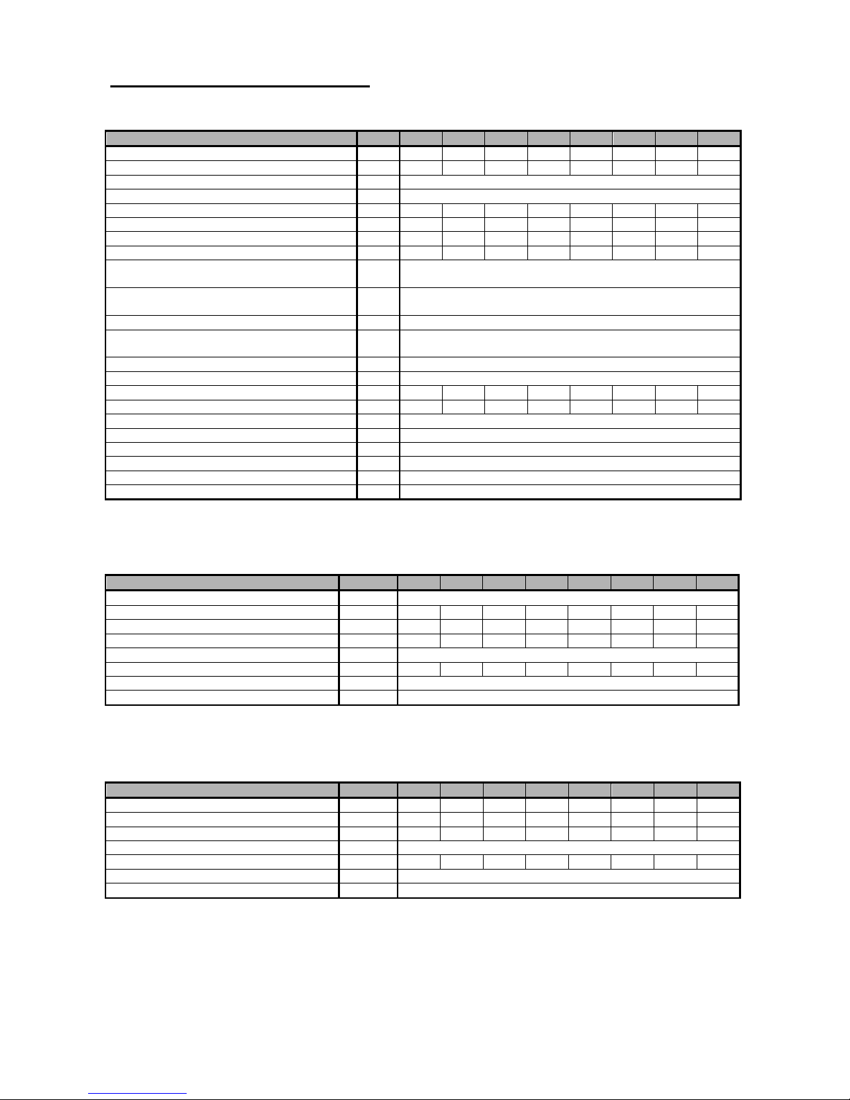
3. Technical data of boilers
Tab. no. 1 Dimensions, technical parameters and electric values of boiler
Fuel efficiency: natural gas 33,99 MJ/kg fuel oil extra light (TOEL) 42,7 MJ/kg
Number of sections
pc 3 4 5 6 7 8 9 10
Weight kg 218 252 282 312 347 377 417 448
Water space volume l 31,5 36,2 40,9 45,6 50,3 55,0 59,7 64,4
Diameter of smoke socket mm 156
Boiler dimensions: - height incl. OS 03 x width mm 1008 x 520
- depth L mm 434 530 626 722 818 914 1010 1106
Volume: - of combustion chamber m3 0,037 0,046 0,058 0,069 0,080 0,092 0,104 0,115
- of fume ducts m3 0,028 0,063 0,08 0,097 0,114 0,131 0,148 0,165
Combustion gas volume m3 0,065 0,109 0,138 0,166 0,194 0,223 0,252 0,280
Water working overpressure kPa
(bar)
400
(4)
Water test overpressure kPa
(bar)
800
(8)
Pressure loss - see.Fig.. no. 1
Recommended heating water operating
temperature
°C 60 – 80
Noise level dB Does not exceed the level 65 dB (A)
Chimney draught mbar Min. 0,05
Tensile loss mbar 0,17 0,21 0,24 0,28 0,31 0,36 0,39 0,43
Overpressure in the combustion chamber mbar 0,01 0,03 0,05 0,08 0,11 0,14 0,17 0,2
Boiler connections – heating water DN 50
– return water DN 50
Connecting voltage 1/N/PE 230 V AC 50 Hz TN - S
Electric input kW Max. 0,1
Electric coverage IP 40
Environment basic AA5/AB5 ČSN 33 2000-1 ed. 2
The values independent on the type of used central burner are shown in burner documentation.
Tab. no. 2 Thermal-technical parameters of boiler designated for natural gas combustion
(Fuel efficiency 33,99 MJ.m-3, air temperature 15 °C and bar. air pressure 1013,25 mbar)
Number of sections
pc 3 4 5 6 7 8 9 10
Appliance category I 2H
Output kW 17,7 23,3 29,1 34,9 40,7 46,5 52,3 58,1
Input kW 20.11 26.5 33 39,6 46,5 52,8 59,4 66
Standby loss kW 0,23 0,26 0,30 0,33 0,36 0,39 0,42 0,44
Efficiency % 89
Combustion products weight 9,5% CO2 kg.hod
-1
33,5 44,1 55,2 66,1 77,2 88,2 99,2 110
Combustion products temperature °C Max. 240
Fuel connecting overpressure mbar 18
Tab. no. 3 Thermal-technical parameters of boiler designated for combustion of fuel oil extra light
(TOEL)
(Fuel efficiency 42,7 MJ.kg-1, air temperature 15 °C and bar. air pressure 1013,25 mbar)
Number of sections
pc 3 4 5 6 7 8 9 10
Output kW 17,7 23,3 29,1 34,9 40,7 46,5 52,3 58,1
Input kW 19.9 26.1 32,7 39,2 45,7 52,2 58,8 65,3
Standby loss kW 0,23 0,26 0,30 0,33 0,36 0,39 0,42 0,44
Efficiency % 89
Combustion products weight 13% CO2 kg.hod
-1
30,2 39,6 49,7 59,6 69,4 79,3 89,3 99,2
Combustion products temperature °C Max. 240
Fuel connecting overpressure mbar According to the boiler manufacturer ´s recommendation

5
0
50
100
150
200
250
300
15 20 25 30 35 40 45 50 55 60
Fig. no. 1 Pressure loss
Number of sections
3 4 5 6 7 8 9 10
L (mm)
434 530 626 722 818 914 1010 1106
Fig. no. 2 Boiler main dimensions
4. Description
4.1 Boiler construction
The main part of boiler is the cast-iron sectional boiler drum made of grey cast iron according to
ČSN 42 2415 or ČSN 42 2420.
The pressure parts of the boiler correspond to the strength requirements according to EN 297, EN 303-1,
EN 303-2.
VIADRUS HERCULES U 22 boiler has a cast-iron closed overpressure combustion chamber. This is a boiler
with three draughts.
The boiler drum is assembled of sections by means of forced on insertions and tightened with the anchor
bolts. The sections create the combustion space, the water space and the convective part. Heating water
input and output are situated in the rear part of boiler.
The rear section of boiler in its upper part has a smoke extension and a heating water flange, in the lower
part a return water flange with a mouthpiece for draining and filling taps.
To the front section there are mounted closing plates serving for an easy boiler maintenance. The lower
closing plate is prepared for the pressure burner assembly.
For a better utilization of heat contained in combustion products there is installed a partition separating the
combustion products flow in the boiler drum. In the rear part of boiler there is placed a fireclay shaped piece
for protection of boiler drum against unwanted thermal effects. In case of 7-10 sectional version there are
used two kinds of central sections: in the front part of the boiler the sections are without the strip, in the rear
part of boiler they are with the strip. The strip closes the combustion chamber and returns the flame and
combustion products from the rear space into the front part it means through a return way in smoke draughts
the combustion products temperature is perfectly utilized.
Numbers of sections without a strip and with a strip are shown in table as follows:
Pressure loss
Pa
Output in kW

6
Tab. no. 4 Central sections of boilers
Boiler size in number of sections
2 3 4 5 6 7 8 9 10
Central section with a strip - 1 2 3 4 4 5 5 6
Central section without a strip - - - - - 1 1 2 2
1. Boiler drum
2. Rear Fire-clay shaped piece
3. Combustion section partition
4. Fire-clay fillet 166
5. Combustion space partition right
6. Combustion space partition left
7. Closing plate - upper
8. Closing plate –lower
9. Smoke extension
10. Sealing
11. Heating water flange
12. Return water flange
13. Filling and draining tap
14. Well G ½“
15. Check valve for the manometer
16. Boiler shell with insulation
17. Closing lid
18. Plug
19. Clip MEOS
20. Control box OS 03
Fig. No. 3 Diagram of boilers
In the upper part of the rear section there is installed a clack-valve of thermo-manometer and a reservoir for
thermostat and thermometer sensors. In the lower part of smoke extension there is installed a cleaning
cover. The explosive flap belongs to the lower closing plate. The burner connection to fuel supply and
refilling is done according to the instructions stated in burner documentation.
The whole boiler drum is insulated with health harmless insulation which reduces losses related to heat
transfer into environment.
7
The boiler steel shell surface is painted by using a good quality coloured comaxite paint.
Tab. no. 5 Combustion space partitions
number of sections
3 4 5 6 7 8 9 10
Combustion section partition - 1 1 2 2 3 3 3
Tab. no. 6 Fire-clay lining
number of s
ections
3 4 5 6 7 8 9 10
Rear Fire-clay shaped piece 1 1 1 1 1 1 1 1
Fire-clay shaped piece of covering
plate
1 1 1 1 1 1 1 1
Fire-clay fillet 160 x 123 x 20 - - 2 - - 2 - Fire-clay fillet 83 x 12 x 20 - 2 - - 2 - - 2
Fire-clay fillet 250 x 123 x 20 - - - 2 2 2 4 4
4.2 Control, safety and regulation elements
All regulation and safety elements are situated in OS 03 control electric box.
The thermomanometer, a compound gauge serves for outlet water temperature and water pressure in
system determination, the thermostat serves for setting the heating water outlet temperature, the main switch
serves for switching on the boiler to get started. The burner defect is signalled by lighting up the LED called
“burner fault”. Boiler overheating above the safe limit 90 °C is signalled by lighting up the LED called
„overheated“ a at the same time the safety thermostat is blocked (if the boiler burner switches off).
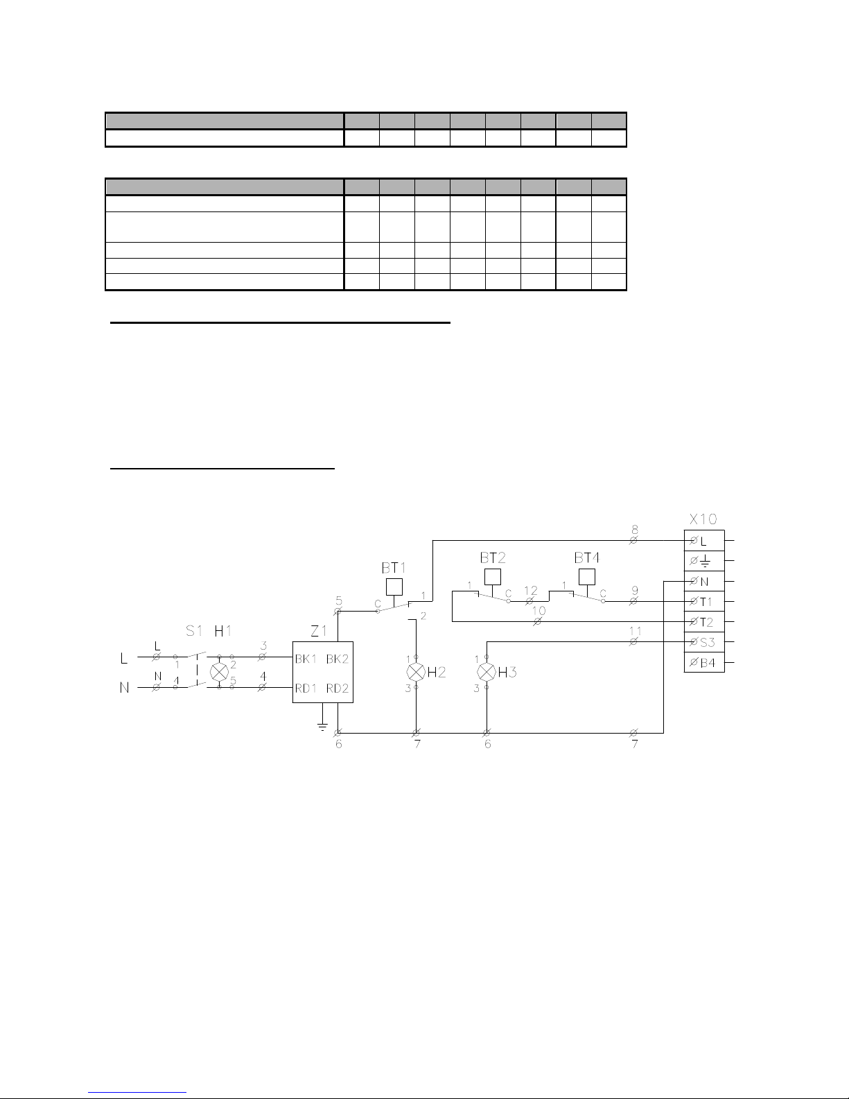
4.3 Boilers wiring diagrams
ϑ
ϑ ϑ
LEGEND:
S1 MAIN SWITCH
H1 „ON“ SIGNALLING
Z1 SUPPRESSION COMPONENT
BT1 SAFETY THERMOSTAT
H2 BT1 SIGNALLING
BT2 SERVICE THERMOSTAT
BT4 ROOM THERMOSTAT (BOILER OUTSIDE CONTROL)
H3 BURNER DEFECT SIGNALLING
X1 TERMINAL BOARD
X10 BOILER CONNECTOR
Fig.no. 4 Elementary wiring diagram of with OS 03 box

8
ϑ
ϑ
LEGEND:
S1 MAIN SWITCH
H1 „ON“ SIGNALLING
Z1 SUPPRESSION COMPONENT
BT1 SAFETY THERMOSTAT
H2 BT1 SIGNALLING
BT2 SERVICE THERMOSTAT
BT4 ROOM THERMOSTAT (BOILER OUTSIDE CONTROL)
H3 BURNER DEFECT SIGNALLING
X1 TERMINAL BOARD
X10 BOILER CONNECTOR
Fig.no. 5 Elementary wiring diagram of with OS 03 boxes
BOX
OUTSIDE CONTROL (OUTSIDE CONTROL)
(OUTSIDE CONTROL)
 Loading...