

Viadrus G 90 Operation And Installation

Hercules U26
Návod k obsluze
VIADRUS G 90
MANUAL FOR BOILER OPERATION
AND INSTALLATION

2
Table of contents: page
1. Purchase order and accessories ...............................................................................................................3
1.1 Purchase order ..................................................................................................................................3
1.2 Delivery a accessories ......................................................................................................................3
2. Boiler usage and advantages ....................................................................................................................4
3. Boiler technical data ...................................................................................................................................4
4. Description .................................................................................................................................................6
4.1 Boiler construction .............................................................................................................................6
4.2 The boiler assembly ..........................................................................................................................6
5. Regulation ..................................................................................................................................................9
5.1 Control, security and regulating elements. ........................................................................................9
5.2 Electrical diagrams ......................................................................................................................... 13
6. Positioning and installation ..................................................................................................................... 22
6.1 Regulations and guidelines ............................................................................................................ 22
6.2 Positioning possibilities .................................................................................................................. 23
6.3 Connection to the hydraulic system ............................................................................................... 24
7. Commissioning – instructions for a contracting service organization ..................................................... 25
7.1 Checking activity before commissioning ........................................................................................ 25
7.2 Commissioning ............................................................................................................................... 25
7.3 Setting and regulation of the boiler heat output ............................................................................. 25
7.3.1 Setting and regulation of the boiler heat output for 8 sectional boiler size ................................ 25
7.3.2 Heat output setting and adjusting at the boiler equipped with Honeywell electromagnetic gas
valves for the sizes with 10, 12 and 15 sections: ...................................................................... 26
7.3.3 Heat output setting and adjusting at the boiler equipped with Honeywell electromagnetic gas
valves for the sizes with 10, 12 and 15 sections: ...................................................................... 27
8. Boiler service by user .............................................................................................................................. 29
9. IMPORTANT WARNINGS ...................................................................................................................... 30
10. Maintenance ....................................................................................................................................... 31
11. Defects and their elimination .............................................................................................................. 32
12. Instructions for product disposal after its service life. ......................................................................... 33
13. Guarantee and responsibility for the faults ......................................................................................... 33

3
Dear customer,
thank you for having purchased VIADRUS G 90, the gas boiler thus having shown your confidence in
VIADRUS a.s.
In order to get used to the correct way of using your new product from the very beginning please
read carefully this service instruction (first of all the chapter no. 8 – Boiler service by user and
chapter no. 9 – Important warnings). Please observe the below stated information specially those
regarding the prescribed annual inspections carried out by an authorized professional firm providing
the guarantee for a long-term failure-free boiler operation both to your and our satisfaction.
1. Purchase order and accessories
1.1 Purchase order
In the purchase order it is necessary to specify:
1. The boiler size and the required regulation (according to the o
rder specification code)
In the purchase order it is necessary to specify the data according to the order specification code.
In case of a delivery in the composed state it is necessary to specify the execution of the right (when
looking at the electric panel the smoke flue is situated on the right) or left (when looking at the electric
panel the smoke flue is situated on the left).
2. Number and types of sensors: - outside temperature sensor QAC 31
- submersible temperature sensor QAZ 21 (can also be used for HWS
heating)
- surface temperature sensor QAD 21
3. Space instrument type: - indoor sensor QAA 70
- indoor sensor QAA 50
1.2 Delivery a accessories
Delivery
VIADRUS G 90 boiler is delivered on a pallet equipped with a cardboard package and as a standard in a
composed state equipped only with a network module. At request a delivery in a decomposed state is
possible.
The accessories delivered at request are not included in the boiler basic price:
- regulation A1 - A4 (according to the o
rder specification code) including 1 pc submersible sensor QAZ 21
- electromagnetic gas valve (according to the order specification code)
- ordered number of necessary types of sensors (see chapter no. 1.1)
- ordered type of space instrument (see chapter no. 1.1)
Order specification code (type designation)
G 90
X X X X X
Regulation:
0 – Standard delivery: electric panel equipped with only a network module, thermomanometer and blind flanges
6 – Regulation A1: 1 pc regulator RVA 43.222 set of connectors SVA 43.222, terminal board WAGO 63 with
a conductor bundle 43, submersible sensor B2 (type QAZ 21).
7 - Regulation A2: 1 pc regulator RVA 43.222, 1 pc regulator RVA 46.531, set of connectors SVA 43.222
a SVA 46.531, terminal board WAGO 46 with a conductor bundle 46, submersible sensor
B2 (type QAZ 21).
8 - Regulation A3: 1 pc regulator RVA 63.280, set of connectors SVA 63.280, terminal board WAGO 63 with
a conductor bundle 63, submersible sensor B2 (type QAZ 21), outside sensor B9
(type QAC 31).
9 - Regulation A4: 1 pc regulator RVA 33.121, set of connectors SVA 33.121, terminal board WAGO 33 with
a conductor bundle 33, submersible sensor B2 (type QAZ 21)
Regulation is delivered in a separate package. The regulators must be connected to the electric panel in place of the
boiler installation.
At the regulation A2 in case of the only one pump circuit required there isn’t necessary to order a mixing circuit
RVA 46.531 incl. the accesso
ries.
Number of sections:
8: 8 sections
10: 10 sections
12: 12 sections
15: 15
section
s
Way of delivery:
S: composed state
R: decomposed state
Gas valve:
H: HONEYWELL
D: DUNGS
Fuel:
Z: natural gas
4
2. Boiler usage and advantages
Cast-iron sectional gas boiler VIADRUS G 90 is equipped with law-emission atmospheric burner and is
intended for burning pf low-pressure natural gas. The boiler is made in B
11BS
design it means it is equipped
with combustion gases reflux fuse. It is suitable first of all for heating the middle–sized and bigger premises.
The use of gas valves with an automatic control and watch of the gas cap tightness at the burner makes it
possible to install the boilers in the boiler rooms of categories I and II. The boiler is only made as the hotwater boiler with a forced circulation and work overpressure up to 400 kPa (4 bar). Before the dispatch the
boiler is tested for tightness by 800 kPa (8 bar) testing overpressure.
Boiler advantages:
1. High service life of the cast-iron boiler drum.
2. Simple operation and maintenance.
3. Reliable security and control elements
4. Gas combustion efficiency 92 %.
5. As a standard equipped with combustion gases reflux fuse.
6. Silent running and law electricity consumption.
7. Gas connected either from the left-hand side or from the right-hand side.
8. Connection of the output and return water either from the left-hand side or from the right-hand side (it
doesn’t apply to the 8-sectional version).
9. Possibility to connect the boiler in an cascade.
10. Possibility to equip with an equitherm regulation.
11. Two-stage burner (nominal/ reduced output).
12. Possible delivery in a decomposed state.
The content of harmful substances in the combustion gases is significantly lower than the values prescribed
by the guideline MŽP 05 – 98 „Environmentally friendly product “ and meets the requirements of the most
strict European standards.
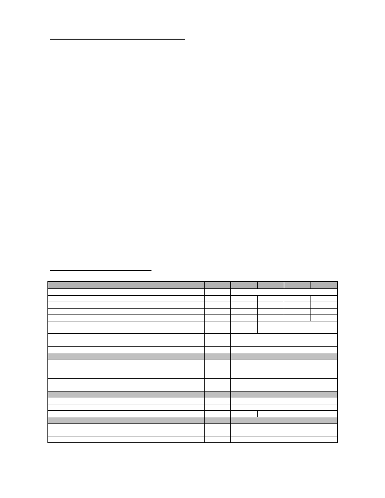
3. Boiler technical data
Tab. no. 1 Dimensions, service temperatures and electric parameters of the boiler
Number of sections
pc 8 10 12 15
Appliance category I2H
Weight kg 242 339 399 489
Water space volume l 27,7 34,3 40,9 50,8
Diameter of smoke socket mm 200 200 225 250
Boiler overall dimensions - depth mm 995 1155 1315 1555
- width x height mm 878,5 x
1160
941x1160
Max. water operating overpressure kPa (bar)
400 (4)
Min. water operating overpressure kPa (bar)
30 (0,3)
Testing water overpressure kPa (bar)
800 (8)
Max. heating water operating temperature °C 85
Min. return water temperature °C 50
Input gas overpressure mbar 18
Noise level dB Does not exceed the 55 dB (A) level
Chimney draught mbar Minimum 0,025
Boiler connections - heating water Js 6/4"
- return water Js 6/4"
- gas Js 1/2" 1“
Connecting voltage 1/N/PE 230 V AC 50 Hz TN-S
Electric input W 50
Electric protection IP 40

5
Tab. no. 2 Thermal parameters of boiler
(heating value 33,99 MJ. m
-3
, gas temperature 15°C and bar. air pressure 1013,25 mbar)
Number of sections
pcs 8 10 12 15
Rated thermal output max. kW 64 80 96 120
Rated thermal output min. kW 49 56 67 84
Rated thermal output max kW 71 87 105 127
Rated thermal output min kW 55 61 73 94
Volume gas flow at the maximum thermal output m3.h
-
1
7,16 9,25 11,32 13,61
Volume gas flow at the minimum thermal output m3.h
-
1
5,56 6,5 7,85 10,05
Efficiency at the maximum thermal output
%
91 92
Efficiency at the minimum thermal output
%
89 92
Temperature of the combustion gases after the draught diverter at
the maximum thermal output
°C 122 129 114 118
Temperature of the combustion gases after the draught diverter at
the minimum thermal output
°C 98 95 95 88
Volume of dry combustion gases actual at the maximum thermal
output
m3.m
-3
20,18 15,8 21,6 18,13
Volume of dry combustion gases actual at the minimum thermal
output
m3.m
-3
23,63 20,1 24,8 23,6
Emission values - CO mg.m
-
3
5 6 8 7
- NOx mg./kWh 33 33 27 23
Grade of NOx grade V
Nozzle diameter
mm 2,42
Honeywell VR 4601 and VR 4605 valves
Informative gas pressure at the nozzle for the nominative output at
the maximum thermal output
mbar 15 14,8 14,5 14
Informative gas pressure at the nozzle for the nominative output at
the minimum thermal output
mbar 9 7,6 7,5 7,5
Dungs MB – ZRDLE 412 valve
Informative gas pressure at the nozzle for the nominative output at
the maximum thermal output
mbar - 13,8
Informative gas pressure at the nozzle for the nominative output at
the minimum thermal output
mbar - 7
Heating water pressure loss
0
2000
4000
6000
8000
10000
12000
14000
16000
18000
20000
0 2 4 6 8 10 12
volume water flow V (m3/h)
pressure loss p (Pa)
Fig. no. 1 Diagram showing the dependency between the boiler exchanger pressure loss and the
water volume flow p = f (V)
15 sections
8,10 sections
12 sections

6
4. Description
4.1 Boiler construction
The main boiler segment is the iron-cast sectional boiler drum made of grey cast-iron in compliance with:
EN 1561 cast-iron 200
The pressure segments of the boiler conform to the strength requirements in compliance with:
EN 656 Gas – fired central heating boilers – Type B boilers of nominal heat input exceeding 70 kW
but not exceeding 300 kW
The main boiler segment is the iron-cast sectional boiler drum. The individual sections are connected by
means of forced-on insertions and tightened by means of the anchor bolts, thus creating a combustion space
with convection surface for combustion gases heat transfer into the heating water. In the upper part of outer
sections on the side where the electric panel is positioned there is screwed a basin for thermometer, the
capillary thermostats sensors and the clack valve for thermomanometer. The connecting points (heating
water input and output, gas) are situated in the rear end of the boiler. The whole boiler drum is insulated with
a harmless mineral insulation which reduces the losses caused by heat transmittance into the surroundings.
To the upper part of the boiler drum there is mounted by means of the screws a built-in draught diverter with
a mouthpiece for setting-on a stove-pipe to lead away the combustion gases into the chimney. The draught
diverter is made of the stain steel and equipped with a dismountable cleaning cover.
The whole boiler drum is seated on a steel basement a part of which is the protective plate made of the stain
steel. The atmospheric burner composed of oval low-emission burner tubes is made of the stain steel.
Individual tubes are mounted on the burner plate by means of four screws screwed in the plate. A
progressive burner construction enables to close fully the boiler combustion space. All air needed for
combustion is brought into the burner tubes through the diffusers. To the burner plate there is welded a gas
distributor with nozzles and there is mounted a pilot burner and a watching electrode.
The boiler control is situated on the control panel in the upper front end of the boiler. The steel surface of the
boiler shell is in colour treated by applying a good quality comaxite coat.
4.2 The boiler assembly
The boiler assembly is described in the „Assembly manual“.
1. The boiler assembly is to be done in place where the boiler will be installed. (it is necessary to
respect all boiler positioning requirements defined in chapter no. 6) according to the project
documentation. The boiler must stand fast and well –balanced on a fireproof pad in vertical position.
2. The connection to the heating system is to be done according to the elaborated project.
3. The combustion gases reflux fuse must not be put out of operation. It is forbidden to interfere in
any way with the combustion gases reflux fuse. For the assembly of the combustion gases reflux
fuse and the exchange of its faulty parts only the original parts delivered by the manufacturer are
allowed to be used.
4. The connection to the chimney can only be done with the agreement of a competent chimney
sweepers´ firm. The boiler connection to gas and heating system.

7
Number of sections
8 10 12 15
L [mm] 995 1155 1315 1555
L1 [mm] 815 975 1135 1375
A [mm] 878,5 941 941 941
D [mm] 200 200 225 250
Fig. no. 2 The main dimensions of the boiler
Gas inlet

8
1 – boiler drum
2 – boiler shell
3 – regulation and safety elements
4 – gas fitting
5 – horizontal draught diverter
6 – atmospheric burner
Fig. no. 3 Boiler assembly

9
5. Regulation
5.1 Control, security and regulating elements.
As a standard the boiler is delivered without the supreme regulation and is equipped with a control panel incl.
a network module.
The manufacturer doesn’t recommend to operate the boilers without the supreme regulation. The standard
version (without the regulation) is designed for the customers who have their own boiler control system.
Besides the network module in the control panel there is mounted an instrument cluster - thermomanometer
The network module is equipped with the elements as follows:
- The main switch with signalling
- Temperature excess signalling (safety thermostat and combustion gases reflux fuse)
- Automatics unblocking incl. the fault signalling
- safety thermostat unblocking (at the open systems keep the setting from the manufacture it means
97 °C, at the closed systems with a pressure expansion reservoir can be set up to 105°C)
- the combustion gases reflux fuse unblocking (set to 75 °C)
- the boiler thermostat (as a standard it is delivered in the range between 0 and 85°C)
- the sensor of combustion gases reflux fuse is positioned in the horizontal draught diverter and in case
that there is an insufficient flue gas installation the sensor switches off the boiler. The sensors of both the
boiler and safety thermostats of the thermometer and manometer clack valve are installed in the basin
(in the upper part of the left outer section).
At request there is delivered to the boiler one of four kinds of regulation or their combinations
according to the ordering key stated in chapter no. 1.1. The regulators are delivered in a separate
package and in place of boiler installation they are mounted into the control panel as directed. The
vacancies in the panel are in a standard delivery equipped with blind flanges.
The most important characteristics of Landis&Staefa regulators:
• an equitherm regulation
• a quick attenuation and a quick change in heating medium temperature (a quick attenuation and a quick
firing)
• The summer/ winter operation is switched-over automatically
• The boiler is unloaded when being started
• The boiler is protected against overheating (the pump after-running)
• The boiler heating water minimum and maximum values (heating water temperatures at the boiler
output) are set
• An antifreeze protection is guaranteed for plant and equipment
• The pumps protection by their regular starting.
• The heating time schedule programme (can be programmed separately every day during the week)
• The possibility of mutual co-operation among up to 16 regulators of RVA series
• In case that the ether QAA50 or QAA70 indoor gadget is connected there is the possibility of boiler
remote control and there is guaranteed the adaptation of heating curves depending on the building
structure and the heat demand
On the top of it the RVA 33.121, RVA 43.222 and RVA 63.280 regulators have:
• The function of a "chimney sweeper " – the boiler is automatically put into operation for required
measurement of combustion gases – the boiler is operated in full swing regardless the set automatic
regime.
• Registration of running hours and number of burner starts.

10
A1 – RVA 43. 222 EQUITHERM REGULATOR
is a boiler and heating circuit regulator for a double stage burner incl. the possibility to prepare HWS
(hot supply water), with a pump heating circuit (without the mixing valve).
Other regulator characteristics are as follows:
• the regulation of heating circuit with a circulating
pump (without the mixing valve)
or:
• connection in a cascade (up to 4 boilers)*
A2 - RVA 46. 531 + RVA 43.222 EQUITHERM REGULATOR
is a set of boiler and heating circuit regulators for a double stage burner incl. the possibility to prepare
HWS (hot supply water), with a mixing valve in the heating circuit.
Other regulator characteristics are as follows:
• Suitable first of all for connection in a cascade
(up to 4 boilers) *
A3 - RVA 63.280 EQUITHERM REGULATOR
is a boiler and heating circuit regulator for a double stage burner incl. the possibility to prepare HWS (hot
supply water), with two sensors and two mixing valves.
Other regulator characteristics are as follows:
• the heating circuits can be set as independent
(two separate heating circuits) or as dependent
(floor heating in combination with radiators)
• a separate time schedule programmed for HWS
(hot supply water) preparation
A4 - RVA 33. 121 EQUITHERM REGULATOR
is a boiler and heating circuit regulator for a single stage burner incl. the possibility to prepare HWS (hot
supply water), with a pump heating circuit (without the mixing valve).
Other regulator characteristics are as follows:
• a separate time schedule programmed for HWS
(hot supply water) preparation
• no other RVA regulators can be connected
* Note:
When connecting in a cascade each of the boilers must be equipped with RVA 43.222 regulator and
at least one of the boilers also with RVA 46.531 regulator (the number of RVA 46.531 regulators must
conform to the number of controlled heating circuits).
The regulator is enclosed according to the purchase incl. a separate operation manual. As a standard
the regulators are delivered together with QAZ 21, a submersible sensor for heating water
temperature.
11
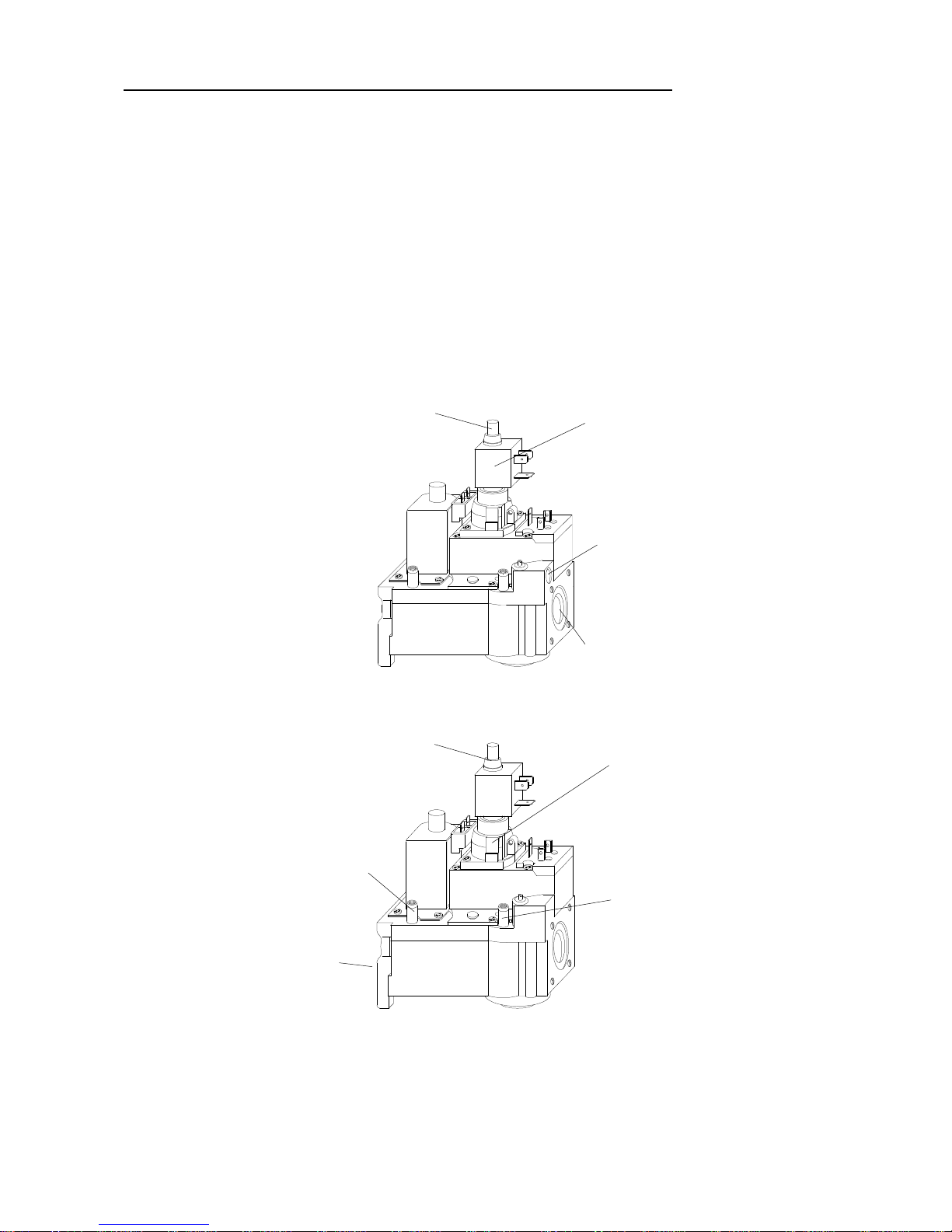
The boiler by customer´s request can be equipped with the security gas fitting:
1. VALVES FOR BOILER with 8-sections
- HONEYWELL VR 4601 QB 2001 WITH HIGH – LOW REEL (COIL) and a smooth start with an
output at the pilot burner
2. IN PARALLEL CONNECTED ELECTROMAGNETIC GAS VALVES FOR BOILER WITH 10, 12 and
15 SECTIONS
- HONEYWELL VR 4601 QB 2001 WITH HIGH – LOW REEL (COIL) and a smooth start with an
output at the pilot burner
- HONEYWELL VR 4605 QB 2002 B WITH HIGH – LOW REEL (COIL) and a smooth start
- The boiler can be operated with heat output stated in tab. no. 2 (setting to the given nominal heat output
is done by the manufacturer)
- It works in the regime of a nominal/reduced heat output
Fig. no. 4 VR 4601 QB 2001 with High – Low coil/reel and the output to the pilot burner
Fig. no. 5 VR 4605 QB 2002 with High – Low coil/reel without the output to the pilot burner
Cover of nominal and
reduced regulation screw
(internal regulation screw is
accessible after its
unscrewing)
High – Low
coil/reel
Cover of nominal and
reduced regulation screw
(internal regulation screw is
accessible after its
unscrewing)
Measurement of
gas input
pressure
Gas input
into the valve
Gas
pressure
regulator
Gas output
into the burner
Measurement of gas
output pressure (press
ure
at the burner nozzles
Output to the pilot
burner
 Loading...