

Viadrus CLEO K, CLEO Operation And Installation Manual

VIADRUS CLEO
WALL BOILER
OPERATION AND INSTALLATION MANUAL

2
Dear customer
We thank you that you have bought the VIADRUS CLEO boiler thus having
shown your confidence in ŽDB a.s.Bohumín, VIADRUS Heating technology
Enterprise.
For you to get used to a correct way of handling your new product from the
beginning please read at first this manual for its usage . Please follow the
information stated in this manual and especially those regarding the
prescribed annual controls to be done by an authorized specialised firm ,
whereby a long-time and trouble-free boiler operation will be guaranteed to
both your and our satisfaction.
CLEO wall boiler was approved to be operated in the Czech Republic by:
Engineering Testing Institute, State Testing Laboratory no. 202, Brno
on the basis of
Certificate E-37-00098-03, E-37-00105-03
Warm-water natural gas boilers, VIADRUS CLEO K,
and
Certificate E-37-00106-03, E-37-00107-03
Warm-water natural gas boilers, VIADRUS CLEO T
odnutí

3
TABLE OF CONTENTS
1. Manufactured boiler variants............................................................................................................... 3
2. Boiler usage and advantages .............................................................................................................. 4
3. Technical data ..................................................................................................................................... 5
4. Boiler description ................................................................................................................................ 6
4.1. Boiler construction........................................................................................................................ 6
4.2. Control elements......................................................................................................................... 10
5. Positioning and installation ...........................................................Chyba! Záložka není definována.
5.1 Regulations and guidelines......................................................Chyba! Záložka není definována.
5.2 Installation conditions.................................................................................................................. 21
5.3. Positioning.................................................................................................................................. 22
5.4. Delivery and accessories ............................................................................................................ 23
5.5 Boiler assembly ........................................................................................................................... 23
6. Commisioning ................................................................................................................................... 25
6.1 Connection to the system............................................................................................................. 25
6.1.1.Connectioon to the heating system and filling with water.................................................... 25
6.1.2. Gas connection..................................................................................................................... 25
6.1.3.Connection to the electricity network ................................................................................... 26
6.1.4. Space thermostat connection ( regulator)............................................................................. 26
6.2. Boiler startup .............................................................................................................................. 27
6.3. Setting the boiler minimum and maximum output for heating................................................... 27
7. Boiler operation by user .................................................................................................................... 28
8. Maintenance ..................................................................................................................................... 29
8.1 Equipment inspection ................................................................................................................. 29
9. Instructions for product disposal after its service life extinction ...................................................... 31
10. Guarantee and liability for defects ................................................................................................. 32
1. Manufactured boler variants
In the purchase order you must specify the following data :
Purchase order specification code
VIADRUS CLEO X
K : smoke outlet into the chimney
T : smoke outlet into via a forced flue gas installation –
TURBO

4
2. Boiler usage and advantages
VIADRUS CLEO wall boiler with a flow-heater is designated for combustion of low-pressure natural gas.
The size of the wall boiler is suitable both for heating the houses, leisure amenities and for reconstruction of the
heat sources in individual tenements. The wall boiler output is between 8 and 24 kW.
The maximum working overpressure of the boiler is 3 bar and its working temperature is up to 85°C with
connection to a heating system with forced heating water circulation ( closed system). The system filling
pressure must be 1 – 1,5 bar when the system is cold.
The wall gas boiler is constructed with the highest efficiency and minimum emissions into the atmosphere,
whereby the environment is significantly saved . The boiler output is fully controllable , automatically operated
by a microprocessor in both regimes and in the whole output range. The boiler is easily adjustable to the needs
of building in a dependence on the heat losses. Its high technical level is guaranteed by the use of the top quality
components made by the world manufacturers. VIADRUS CLEO with water flow heating is manufactured in
two variants - one with venting into the chimney and another one is the Turbo design.
Boiler advantages :
1. A high combustion efficiency
2. Boiler continual output modulation
3. Easy operation
4. Reliability of regulation and safety elements
5. Low weight

5
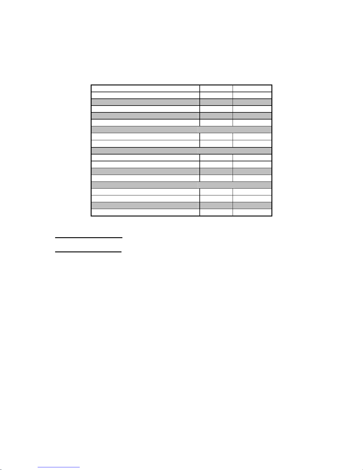
3. Technical data
operating temperature and electric values
VIADRUS
CLEO K
VIADRUS
CLEO T
Type of fuel [-] ZP ZP
Appliance category [-] I2H I2H
Design B11BS C12
Weight [kg] 40 40
Expansion tank volume [l] 8 8
Boiler dimensions – width [mm] 460 460
- depth [mm] 350 350
- height [mm] 705 705
Water working overpressure for
CH(central heating) circuit
[bar] 3 3
Water working overpressure for
HSW(hot service water)
[bar] 6 6
Minimum working pressure for CH [bar] 0,8 0,8
Minimum working pressure for HSW [bar] 1 1
Water testing overpressure [bar] 6 6
Maximum permissible working
temperature
[°C] 85 85
Fuel connecting overpressure [mbar] 20 20
Minimum fuel connecting overpressure [mbar] 14 14
Number of nozzles [-] 13 13
Nozzles diameter - VIADRUS CLEO
K
[mm] 1,25
Nozzles diameter - VIADRUS CLEO
T
[mm] 1,15
Noise level [dB] < 55 < 55
Boiler connection
- heating water outlet [Js] 3/4“ 3/4“
- HSW heating water outlet [Js] 1/2“ 1/2“
- return heating water inlet [Js] 3/4“ 3/4“
- return heating water inlet from heater [Js] 1/2“ 1/2“
- gas supply [Js] 1/2“ 1/2“
- smoke flue connection [mm] 130 -
- forced flue gases installation
connection
[mm] - 100/60
Connecting voltage 1/N/PE 230V~50 Hz, TN-S
El. intake incl. the pump [W] 130 130
El. protection IP 41 41
6
Tab. č. 2 Thermal – technical parameters
Reference conditions 15°C a 1013,25 mbar, dry gas
Output for CH [kW] 8 – 24
Output for HSW [kW] 8 – 24
Fuel volume flow [m3.h-1] 0,9 – 2,7
Mass rate of flue gases min./max. [g.s-1] 21,9/30,9
HSW flow ∆T 25°C
[l.min
-1
] 13
HSW flow ∆T 35°C
[l.min
-1
] 9
CH outlet temperature regulation [°C] 30-85
HSW outlet temperature regulation [°C] 30-60
Efficiency [%] 90-92
CO [ppm] 7-14
NOx [ppm] 20-50
Combustion gases temperature [°C] 130°C
4. Boiler description
4.1. Boiler construction
VIADRUS CLEO wall boiler with water flow heating is equipped with a copper heat exchanger the whole
surface of which is protected by a silicone paint based on aluminium with a resistance up to 350°C. These
exchangers have separated systems for HSW heating and the heating system. A big advantage of the heat
exchangers is that they save space and weight. The maximum working pressure for CH circuit is 3 bar at the
working temperature of 85 °C and 6 bar for HSW preparation at the working temperature of 85 °C. Minimum
working pressure is 1bar. The heat exchanger is positioned in the upper part of the combustion chamber an
automatic bleeder valve is mounted on it, a part of which ends above the combustion chamber. Due to the
minimum loss caused by the thermal transmission it is necessary to keep the surface of heat exchanger
lamellae clean.
The gas burner has an advanced modular construction and is made of stainless steel. It is positioned in the
lower part of combustion chamber and electrodes are mounted on it, where one of them is the ignition electrode
and another one is the ionisation electrode. The combustion chamber is made of aluminised steel plate with an
internal thermal insulation. Above the combustion chamber (in VIADRUS CLEO T design) there is positioned
the flue gases collector on which there is mounted a flue gases outlet ventilator. This ventilator by means of
silicon hoses is connected to the differential pressure switch ( manostat ). In VIADRUS CLEO K design above
the combustion chamber there is installed the draught diverter on which there is mounted the flue gases
thermostat (surface sensor).
In the upper part of the heat exchanger there are installed the thermal sensors for heating system and HSW.
The internal water circuit in the boiler is made of copper tubes. The closing chamber at VIADRUS CLEO T
design is made of aluminised sheet. The openings in this closing chamber are sealed by means of silicone
bushings. On HSW inlet there is installed the water flow sensor.
This boiler in both designs is equipped with automatic and gradual output control. The main control
element of this boiler is the modular electronic board equipped with a microprocessor which evaluates the
conditions and values of sensors and issues the commands to the gas valve , ignition electronics and circulation

7
pump. On the internal heating water outlet there is installed an emergency thermostat , a pressure switch and a
clack-valve of the manometer for signalling the pressure in heating system.
The emergency thermostat will shut down the wall boiler once the temperature has exceeded 95°C. The
pressure switch will shut down the wall boiler once the pressure in heating system has dropped below 0,8 bar.
Then in the boiler at the heating water input into the boiler there is installed a safety valve. In the by-bass
between HSW inlet and heating water inlet there is installed a ball valve which serves for heating system filling
with water. In the rear part of the boiler there is installed an expansion tank of 8 l volume.

8
Fig.No.1 VIADRUS CLEO T boiler assembly
Legend(down from top): HSW temperature sensor/ air manostat/ bleeder valve/exhaust ventilator/ Expansion
tank/CH temperature sensor/ flue gases collector/ heat exchange/emergency thermostat/ionisation .electrode/

9
ignition electrode/ burner/supporting frame/ pressure switch/ circulation pump/ Honeywell gas valve/ safety
valve/refill valve/ HSW flow sensor
Legend( down from top): Legend(down from top): HSW temperature sensor/ flue gases thermostat/draught
diverter/ bleeder valve/ Expansion tank/CH temperature sensor/ heat exchange/emergency thermostat
/ionisation .electrode/ ignition electrode/ burner/supporting frame/ pressure switch/ circulation pump/ Honeywell
gas valve/ safety valve/refill valve/ HSW flow sensor

10
Fig.No.2 VIADRUS CLEO K boiler assembly
4.2. Control elements
Boiler control front panel
The thermometer measures the outlet water to the central heating. The manometer measures the pressure in
central heating. By means of a button for setting the heating temperature the user sets the heating water in the
system being heated in the range from 35 to 85 °C. The recommended range is from 55 to 85 °C. The button for
HSW temperature setting is by user set to the required hot service water outlet temperature ranging from 35 to
60°C. The emergency status signalisation signals the boiler status when the electronics does not manage to light
(like due to the gas supply interruption). The boiler is returned into the „boiler in operation” position by means
of a position switch. “Boiler in operation “ signalisation signals the boiler in operation regime.
Fig. No. 3 Boiler control panel
Legend: (from the left to the right): HSW regime/ CH + HSW regime/ service function/switched off/ “Boiler in
operation” signal lamp /”Boiler under the voltage” signalisation – “/ failure signalisation
4.2.1. Integrated control system for boiler type AM 56 –IMS 02 code 16 562
Description :
The control automatics of AM 56 – IMS 02 type for suspended boilers with HSW flow heating, with a double
heat exchanger and an automatic ignition.
The control function includes the flame ignition, its control and a continuous modulation. The automatics has
two functional units:
1. burner control unit ( ACCF)
2. control unit and flame modulation ( GMF)
The boiler position switch positions are as
follows :
- Boiler switched off
- summer operation
(HSW generation is in operation)
- winter operation
( the central heating plus HSW
generation are in operation)
- failure de-blocking ( reset)
- service function
Legend: position switch, CH temperature
setting, HSW temperature setting,
thermometer, manometer
11
1. Burner control unit – ignition and ionisation (ACCF)
Electronic device for flame operation and control, for a direct burner ignition by means of a sparkle induced by
the electric discharge and monitoring of flame presence by means of ionisation phenomenon.
Working sequences
By making the demand on heating contacts there is started the auto-test phase testing the flame amplifier and the
parts related to a safe function securing the safety and resulting in ignition sequence start prevention if a failure
appears on these elements.
At the end of the auto-test there starts the safety time during which the voltage is brought to the ignition device
and to the gas valve output.
As soon as the burner is lit and is signalled by the flame presence there is switched off the sparkling and the
boiler operation starts according to the selected regime.
By undoing the requirement contacts the gas valve gets closed and the device is automatically brought into the
waiting status.
If the boiler does not light during the safety ignition, the device switches over into the failure condition with an
automatic reset, there is disconnected the voltage from gas valve outlet and from the ignition unit.
The failure status is detected by the GMF unit signalising the failure.
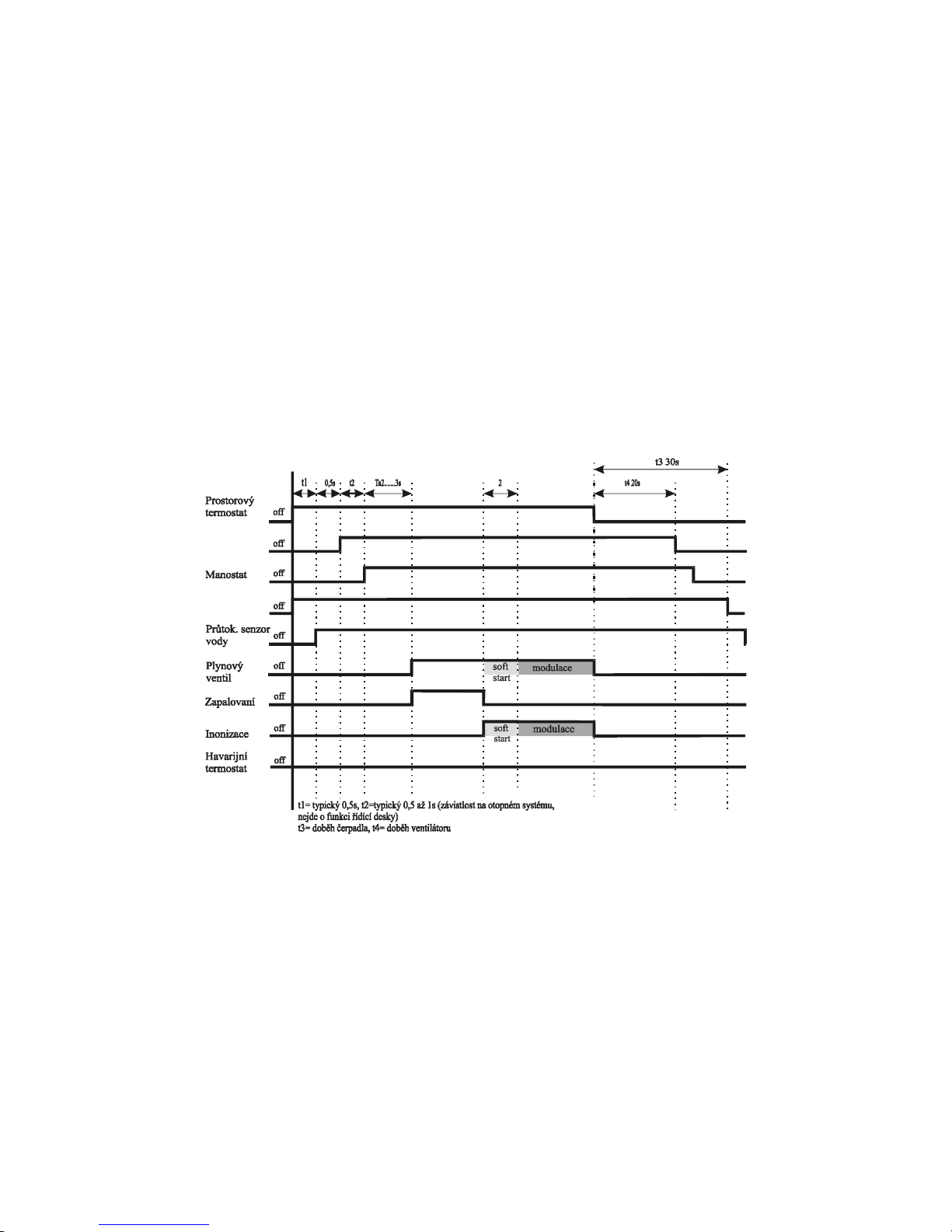
Heating time schedule
Legend(down from top): Space thermostat/ manostat/ water flow sensor/ gas valve /ignition/ ionisation/
emergency thermostat . t1= typical 0,5n, t2= typical 0,5-1 s( dependence on the heating system, it isn’t the
control board function) t3= pump after-running, t4= ventilator after-running.
2. Flame control and modulation unit ( GMF)
General characteristics
- signalisation of the operation and failures by means of LEDs on the board
- suppression of interferences caused by ignition and contacts making
- circulation pump control with an after-running for demand on heating
- ventilator, air flow and after-running functions control
- earth-connector on the board
- 2 AF safety fuse on the board
- phase , zero conductor and grounding connection at the input by means of a screwed connector on the board
- connection of indoor thermostat by means of a screwed connector on the board

12
- emergency thermostat connection
- regime selection in operation and the reset by means of rotating position switch positioned on the board.
- burner switching off in case of primary thermal sensor failure (either an interruption or a short-circuit)
- manual test
Flame modulation section
- the ignition of a burner with time synchronized output and the flame presence assurance , setting by means
of a trimmer on the board
- flame modulation with PWM type current regulation
- setting of HSW and heating water temperatures by means of a thermal sensor positioned near the HSW
output and PID type in the phase on the flame modulation
- HSW and CH temperature control by means of the sensor temperature at the outlet from the primary heat
exchanger and PID type in the phase on the flame modulation
- A function against the frequent switching in heating system which can be set to 180 seconds or it can be
cancelled by inserting a jumper JP3 on the board
- Setting of burner output in the phase of heating by means of a trimmer on the board.
- The type of gas selection can be done by means of JP1 jumper.
Boiler operation
HSW regime
As soon as at the HSW requirement the HSW flow exceeds 3l/min the pump gets blocked. The relay switches on
the requirement and brings the voltage to the automatics. Approximately within 2 seconds after the other gas
valve opening (the gradual start phase) the PID type flame modulation phase starts and continues until the
correct HSW temperature achievement. If the temperature still keeps growing and achieves the switching
temperature the burner switches off. The HSW regime phase is terminated if the HSW flow has dropped
below 2,5 l/min. If in the heating regime the temperature is set above 55°C at the HSW flow below 3 l / min,
the set heating temperature will be limited by 50°C in order to prevent the deposits creation in the heat
exchanger secondary circuit If the HSW outlet temperature has achieved 70°C the burner switches off. After the
demand on HSW termination the pump starts working in order to reduce the calcium deposits creation. The
pump after running time keeps changing between 0,4 and 2 seconds depending on the temperature found out in
the heating circuit at the time of HSW requirement. In case of parallel requirements the HSW regime takes
precedence over the central heating. If the J5 jumper is positioned in ON position, the pump after running time
is always 2 seconds at the end of HSW requirement.
Heating regime
The heating regime starts when the space thermostat has issued the demand on heating and the position switch is
in winter position. There are activated the pump and the ventilator and after having checked the air flow there is
activated the burner control unit. Approximately two seconds after the gas valve opening ( the gradual start
phase) the burner output gets to the minimum set value and during 100 seconds it achieves the maximum
output . As soon as the flame modulation point has been achieved the start function gets stopped and the control
follows PID till the set heating water temperature achievement. In case that the water exceeds the set
temperature by 51°C the burner switches off. It repeatedly lights up 5°C below the set temperature if the time
of protection against a frequent switching has expired. The frequent switching function is terminated if the
indoor thermostat contacts (or the WINTER regime contacts on the position switch) are undone and made or in
case of HSW requirement. If the JP4 jumper is set to ON position the temperatures range is reduced to the value
suitable for floor heating.
Note. There must be always used the equipment limiting the high temperature ( for the floor heating
protection).
Pump control and circulation
The pump switches on at the moment of heating or HSW requirement At the end of every heating requirement
the pump keeps working for 180 seconds. In case that after the working period there occurs a failure in the
heating regime the pump keeps working for the whole time as an after-running into the heating system.
 Loading...