

Viadrus CLAUDIUS K 2 L5X, CLAUDIUS K 2 Series, VIADRUS CLAUDIUS K 2 L3X Manual For Operation And Installation
VIADRUS CLAUDIUS K 2
Manual for boiler operation and installation
GB_2016_35
GB_2016_43

2
Content
p.
1 Manufactured boiler versions ................................................................................................................................ 3
2 Boiler Uses and Advantages ................................................................................................................................. 3
3 Specifications ........................................................................................................................................................ 4
4 Boiler description ................................................................................................................................................... 7
4.1 Boiler construction ........................................................................................................................................ 7
5 Storage heater VIADRUS OV - H 100 ................................................................................................................... 8
6 Placement and installation................................................................................................................................... 10
6.1 Regulations and guidelines ......................................................................................................................... 10
6.2 Positioning options ...................................................................................................................................... 11
6.3 Delivery and accessories ............................................................................................................................ 11
6.4 Boiler Installation......................................................................................................................................... 12
6.5 Wiring diagram ............................................................................................................................................ 13
7 Commissioning .................................................................................................................................................... 15
7.1 Connection to the heating system and filling with water ............................................................................. 15
7.2 Gas connection ........................................................................................................................................... 16
7.3 Connection to the mains ............................................................................................................................. 16
7.4 Condensate drain........................................................................................................................................ 16
7.5 Flue gas exhaust......................................................................................................................................... 16
7.6 Pressure losses of flue gas exhaust components for the boiler VIADRUS CLAUDIUS K2 ...................... 18
7.7 Boiler commissioning .................................................................................................................................. 18
7.8 Boiler settings ............................................................................................................................................. 19
8 Boiler operation by user ....................................................................................................................................... 20
8.1 General description ..................................................................................................................................... 20
8.2 Display description ...................................................................................................................................... 20
8.2.1 Energy saving ......................................................................................................................................... 21
8.3 Settings overview ........................................................................................................................................ 21
8.4 Error messages ........................................................................................................................................... 24
8.5 Faults .......................................................................................................................................................... 24
9 Maintenance ........................................................................................................................................................ 25
9.1 Checking the device ................................................................................................................................... 25
10
IMPORTANT NOTICE .................................................................................................................................... 26
11
Instructions for product disposal after its service life ...................................................................................... 26
12
Warranty and liability for defects ..................................................................................................................... 27

3
Dear customer,
Thank you for purchasing VIADRUS CLAUDIUS K 2 and hence your confidence in the company VIADRUS a.s.
To get used to a correct way of handling your new product, please read at first this manual for its use, particularly
Chapter no. 8 - Boiler operation by users and Chapter no. 10 - Important information. We ask you to follow further
presented information, particularly regarding required annual inspections by a professional company, thus ensuring
trouble-free boiler operation to our satisfaction.
1 Manufactured boiler versions
In the order, please specify the following order specification code:
VIADRUS CLAUDIUS K 2
x1 x2 x
3
x
1
Gas valve:
L:
produced by SIEMENS
x
2
Size:
3:
3-section version
5: 5-section version
x3
Equipment:
1:
without set three-way valve with pump
3: with three-way valve and pump
5: without set three-way valve with pump
2 Boiler Uses and Advantages
Condensing boiler VIADRUS CLAUDUS K 2 is intended for combustion of low pressure natural gas. The size of the
condensing boiler is suitable for heating of houses, recreation facilities and also for reconstruction of heat sources
in individual flats.
Heat output of the condensing boiler is 3.8 to 24 kW (K 2 L3X) and 7.8 to 48.1 kW (K 2 L5X).
The boiler body consists of castings made from special aluminium alloy. Individual sections are connected by
means of silicon rings and tightened by threaded bars. The maximum working overpressure of the boiler is 250 kPa
(2.5 bar). The body is tested by the test overpressure of 600 kPa (6 bar).
Combustion mixture is mixed in a mixer in a predetermined ratio of air - gas in its control range.
Water volume of the three-section boiler body is 9 l and the water volume of the five-section body is 13 l.
The efficiency of the boiler body at a temperature gradient of 50/30 °C ranges from 102 to 108% depending on the
desired performance.
Boiler advantages:
•
Low gas consumption.
•
High combustion efficiency.
•
Continuous output modulation.
•
Easy operation and maintenance.
•
The boiler enables connection to a storage hot service water heater and guarantees its preferential heating.
•
Reliability of regulation and safety elements.
•
Low weight.
•
Automatic detection of faults.
•
Independent time program also for HW.
•
Equithermal boiler regulation.
4
3 Specifications
Tab. №. 1 Sizes, operation temperature and electrical variables
K 2 L3X
K 2 L5X
Fuel type [-] ZP ZP
Appliance category [-] I2H I2H
Weight [kg] 69 95
Water content [l] 9 13
Boiler dimensions - width (L2) [mm] 502 587
- depth [mm] 548 548
- height [mm] 956 956
Ø connection of the combustion air [mm] 80 80
Ø smoke socket [mm] 80 110
Maximum working water overpressure [kPa]/[bar] 250/2.5 250/2.5
Testing water overpressure [kPa]/[bar] 600/6 600/6
Dissipation factor [-] 11.37 6.85
Maximum allowable operating temperature [°C] 85 85
Connecting fuel overpressure G20 [mbar] 20 20
Noise level [dB] < 55 < 55
Boiler connection
- heating water outlet [Js] 3/4“ 3/4“
- heating water outlet to the heater [Js] 3/4“ 3/4“
- return heating water inlet [Js] 3/4“ 3/4“
- return water inlet from the heater [Js] 3/4“ 3/4“
- condensate outlet [mm] Ø 25 Ø 25
- safety valve outlet [Js] 3/4“ 3/4“
- gas inlet [Js] 3/4“ 3/4“
Supply voltage 1/N/PE 230 VAC 50 Hz TN-S
Input power including pumps [W] 110 110
El. protection IP 41 41
Tab. №. 2 Heat-technical parameters
Comparative conditions 15 °C and 1013,25 mbar, dry gas
K 2 L3X
K 2 L5X
Performance B23, B53, C83 B23, B53, C83
Boiler power range [kW] 3.8 - 24 7.8 – 48.1
Rated heat output 80/60 °C [kW] 22.4 45.3
Minimum heat output 80/60 °C [kW] 3.8 7.8
Rated heat output 50/30 °C [kW] 24.3 48.1
Minimum heat output 50/30 °C [kW] 4.3 8.8
Rated heat input [kW] 23.7 47.3
Minimum heat input [kW] 4 8.1
Efficiency at rated heat output 80/60 °C [%] 97.2 97.2
Efficiency at rated heat output 50/30 °C [%] 103.1 102
Efficiency at minimum heat output 50/30 °C [%] 108.2 107.7
Volumetric flow rate of fuel [m3.h
-
1
] 0.408 - 2.4 0.836 – 4.877
Flue gas mass flow [kg.h
-
1
] 5.2 - 39.2 12.26 - 80.85
NOx Class [-] 5 5
Flue gas temperature [°C] 30 - 85 40 - 85
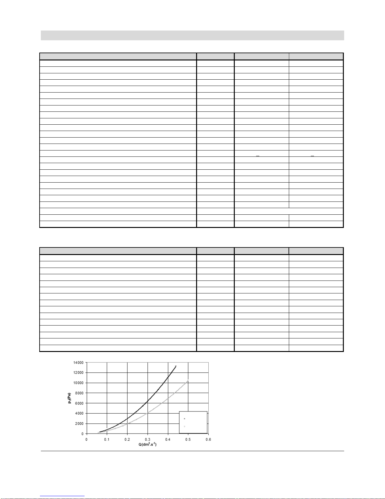
Fig. №. 1 Dependence of the pressure loss on flow
3 sect.
5 sect.

5
Information requirements relating to boiler heaters for space heating, boiler combined heaters and
cogeneration heaters for space heating
Model/Models: VIADRUS CLAUDIUS K2 L3X
Condensing boiler: YES
Low-temperature boiler: NO
Boiler type B1: NO
Cogeneration heater for space heating: NO If YES, featured with an auxiliary heater:
Combined heater: NO
Item
Designatio
n
Value
Unit
Item
Designatio
n
Value
Unit
Rated heat output
Prated
22.7 kW
Seasonal energy efficiency of
heating (***)
ƞ
s
92 %
For the boiler heaters for space heating and boiler
combined heaters: useful heat output
For the boiler heaters for space heating and boiler
combined heaters: useful efficiency
At rated heat output and high
temperature mode (*)
P4
22.7 kW
At rated heat output and high
temperature mode (*)
ƞ
4
87.6 %
At 30% of rated heat output and
low temperature regime (**)
P1
4.3 kW
At 30% of rated heat output and
low temperature regime (**)
ƞ
1
97.6 %
Consumption of auxiliary electrical power: Other items:
At full load
el
max
0.034 kW
Heat loss in standby mode
P
stby
0.088 kW
At partial load
el
min
0.013 kW
Electricity consumption of the
pilot burner
P
ign
- kW
In standby mode
PSB
0.003 kW
Emissions of nitrogen oxides
NOx
12
mg/
kWh
Contact information
VIADRUS a.s.
Bezručova 300
Bohumín
735 81
(*) High temperature mode for condensing boilers mean return temperature of 60 °C at the inlet to the heater and the inlet
temperature 80 °C at the outlet of the heater.
(**) Low temperature for condensing boilers mean return temperature of 30 °C, for low temperature boilers it is 37 °C, and for other
heaters it is 50 °C (at the inlet of the heater).
(***) For seasonal energy efficiency, the value is based on the gross calorific value according to EU regulation no. 813/2013
6
Information requirements relating to boiler heaters for space heating, boiler combined heaters and
cogeneration heaters for space heating
Model/Models: VIADRUS CLAUDIUS K2 L5X
Condensing boiler: YES
Low-temperature boiler: NO
Boiler type B1: NO
Cogeneration heater for space heating: NO If YES, featured with an auxiliary heater:
Combined heater: NO
Item
Designatio
n
Value
Unit
Item
Designatio
n
Value
Unit
Rated heat output
Prated
46.1 kW
Seasonal energy efficiency of
heating (***)
ƞ
s
93 %
For the boiler heaters for space heating and boiler
combined heaters: useful heat output
For the boiler heaters for space heating and boiler
combined heaters: useful efficiency
At rated heat output and high
temperature mode (*)
P4
46.1 kW
At rated heat output and high
temperature mode (*)
ƞ
4
87.8 %
At 30% of rated heat output and
low temperature regime (**)
P1
8.8 kW
At 30% of rated heat output and
low temperature regime (**)
ƞ
1
97.8 %
Consumption of auxiliary electrical power: Other items:
At full load
el
max
0.060 kW
Heat loss in standby mode
P
stby
0.094 kW
At partial load
el
min
0.013 kW
Electricity consumption of the
pilot burner
P
ign
- kW
In standby mode
PSB
0.003 kW
Emissions of nitrogen oxides
NOx
13
mg/
kWh
Contact information
VIADRUS a.s.
Bezručova 300
Bohumín
735 81
(*) High temperature mode for condensing boilers mean return temperature of 60 °C at the inlet to the heater and the inlet
temperature 80 °C at the outlet of the heater.
(**) Low temperature for condensing boilers mean return temperature of 30 °C, for low temperature boilers it is 37 °C, and for other
heaters it is 50 °C (at the inlet of the heater).
(***) For seasonal energy efficiency, the value is based on the gross calorific value according to EU regulation no. 813/2013.
7
4 Boiler description
4.1 Boiler construction
The heat exchanger of the condensing boiler consists of a front, middle (the number depends on the size of the
boiler) and the rear section. These castings are connected by means of silicon rings and tightened by threaded
bars. This boiler is equipped with a premixing burner. Combustion mixture is mixed in a mixer in a predetermined
ratio of air - gas at the whole performance range. Air is supplied to the mixer using the modulation ventilator. The
boiler is constructed for heating with preferred heating of HW. To heat HW, the manufacturer recommends
combination with the water heater.
Further, the boiler is equipped with LMS automatics and a gas valve. LMS automatic is an electronic control and
ignition automatics designed for gas central heating boilers with the modulated ventilator and pre-mixing burner. if
the boiler is to be controlled equithermally, it is necessary to connect the outdoor sensor. In this case, we
recommend using one of the communication devices, see chap. 6.3.
To increase the number of heating circuits, expansion module can be used according to project documentation.
Combustion air can be fed and flue gas can be exhausted to the chimney or through the wall.
The boiler is an appliance of B or C version.
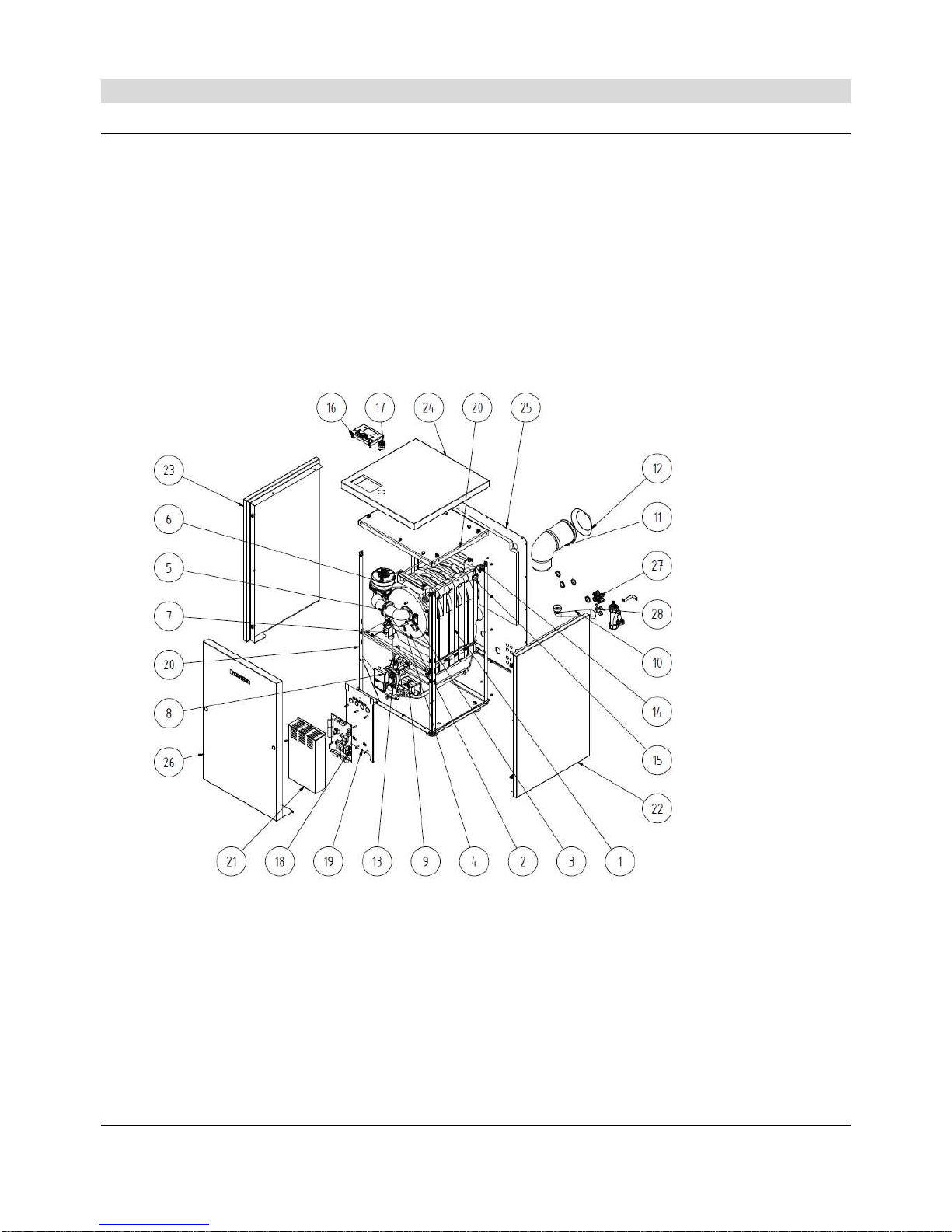
1 Condensing body
2 Burner plate with burner
3 Ignition electrode (guard electrode)
4 Supply of the mixture to the burner
5 Fan
6 Gas valve
7 Pump with a PWM control
8 Three-way valve
9 Condensate drain
10 Exhaust piping
11 Suction piping
12 Inlet pipe to the boiler
13 Outlet pipe from the boiler
14 Manometer check valve
15 SIEMENS display
16 Reset button
17 Manometer
18 Console electro
19 Control panel SIEMENS LMS
20 Housing electro
21 Boiler frame
22 Right side casing part with insulation
23 Left side casing part with insulation
24 Upper casing part with insulation
25 Rear casing part with insulation
26 Front casing part
27 Outlets
28 Blinds
Fig. №. 2 Assembly of the boiler

8
Fig. №. 3 Location mix strainer in the gas pipeline of the burner K 2 L5X
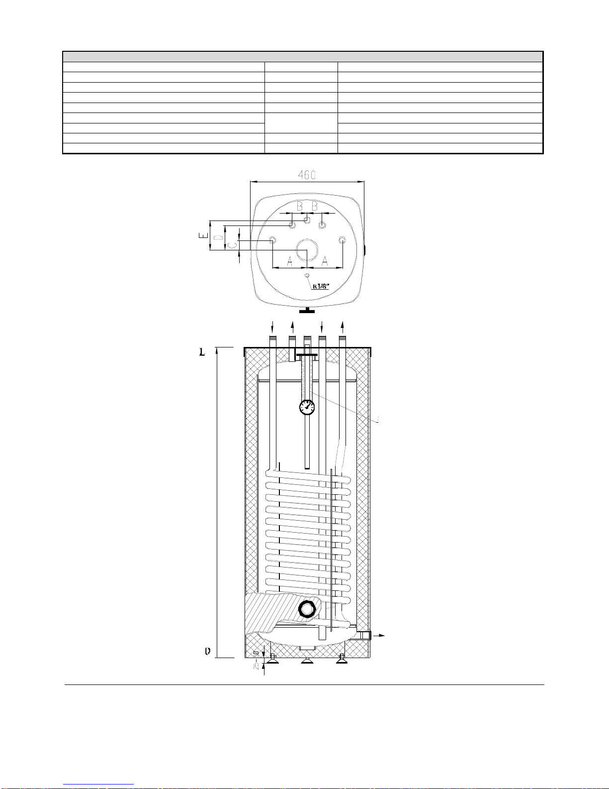
5 Storage heater VIADRUS OV - H 100
Water heater VIADRUS OV – H 100 is a pressure device adapted to operate at a maximum water pressure of 0.6
MPa (6 bar). Hot service water heater is a device designed for heating and storing hot water.
The main part of the heater is a vessel made of steel sheet coated with a layer of enamel. The heater is equipped
with a heating coil with large heat exchange surface, which ensures fast heating of large quantities of water. All
connections are located in the upper part of the heater and are terminated with an external thread. The heater also
offers the possibility of connecting a circulation pump for circulating hot water, and s temperature sensor. There is
an outlet at the bottom part of the heater through which the vessel can be drained. The heater is equipped with an
additional anticorrosive device in the form of a magnesium anode whose function is based on the utilization of the
electrochemical potential difference between the anode and the tank. The magnesium anode is placed in the upper
part in the plug 2”. Thermal insulation of the heater is made of polyurethane foam free from freon, which minimizes
heat loss. An electric heater can be installed in the heater.
Tab. №. 3 Technical parameters
Technical parameters VIADRUS OV – H 100
Volume l 100
Maximum allowable temperature °C 100
Maximum allowable pressure bar 6
Heat exchanger surface m2 1.2
Heat exchanger volume l 5.6
Consumption of heating water from central heating m3/h 2.5
Constant efficiency (70/10/45oC) l/h 700
Output kW 29
Dimen
sions
A mm 140
B mm 60
C mm 40
D mm 100
E mm 120
Device height L 990
Tank dimensions (without insulation) Ø 400
Tank dimensions (with insulation) mm 455x455
Insulation of soft polyurethane foam mm 30
gas
inlet
gas inlet
1. Complete burner
2. Extension tube
3. Gasket Ø 83
4. mix strainer
5. Screw M5
6. Washer 5.3
7.
Nut M5
9
Connections
Cold water / hot water R 3/4”
Circulation R 3/4”
Central heating circulation (supply, return pipeline) R 3/4”
E-socket (heating coil) R 5/4”
Sensor housing R 3/8"
Thermometer
internal thread
1/2”
Water drain 3/4"
Magnesium anode An. stopper 2”
Weight (empty) kg 57
Fig. №. 4 Water heater VIADRUS OV - H 100
ANODE PROTECTION
DRAIN

10
6 Placement and installation
6.1 Regulations and guidelines
a) for the heating system
CSN 06 0310 Heating systems in buildings – Design and installation
CSN 06 0830 Heating systems in buildings – Safety devices
CSN 07 7401 Water and steam for heating equipment with steam working pressure up to 8 MPa
EN 15502-1 Gas-fired central heating boilers - Part 1: General requirements and tests
EN 15502-2-1 Gas-fired central heating boilers - Part 2-1: Specific standard for boilers of design C and
designs B2, B3 and B5, with a nominal heat input not exceeding 1,000 kW
EN 677 Gas-fired central heating boilers – Specific requirement for condensing boilers with a
nominal heat input not exceeding 70 kW
b) for chimneys
CSN 73 4201 Chimneys and flues – Design, implementation and connection of fuel appliances
c) regarding the fire regulations
CSN 06 1008 Fire safety of heat installations.
EN 13501 – 1 + A1 Fire classification of construction products and building elements – Part 1: Classification
using test data from reaction to fire tests
d) for the system HW heating
CSN 06 0320 Thermal systems in buildings – Hot water preparation –Designing and Installation
CSN 06 0830 Heating systems in buildings – Safety devices
CSN 75 5409 Internal Water Supply
e) for the electricity network
CSN 33 0165 Electrical regulations. Marking the conductors with colours or digits. Implementing
regulations.
CSN 33 1500 Electrical regulations. Revision of electrical devices.
CSN 33 2000–1 ed. 2 Low-voltage electrical installations – Part 1. Basic terms of determining the fundamental
characteristics of the definition.
CSN 33 2000–4–41 ed. 2 Low-voltage electrical installations – Part 4-41, Protective measures to ensure safety –
Protection against electric shock
CSN 33 2000-5-51 ed. 3 Low-voltage electrical installations – Part 5-51. Selection and erection of electrical
equipment – Common rules.
CSN 33 2000-7-703 ed.2 Electrical installations of buildings – Part 7-703: Requirements for special installations or
locations – Rooms and cabins containing sauna heaters.
CSN 33 2130 ed. 2 Low-voltage electrical installations – Internal electric distribution lines.
CSN 33 2180 CSN electric engineering regulations. Rules for installation of electrical apparatus and
appliances.
ČSN 34 0350 ed.2 Safety requirements for flexible cords and cables.
EN 60079-10-1 Explosive atmospheres – Part 10-1: Classification of areas – Explosive gas
atmospheres.
EN 60079-14 ed.3 Explosive atmospheres – Part 14: Electrical installations design, selection and erection.
EN 60335 – 1 ed.3 Household and similar electrical appliances - Safety – Part 1: General requirements.
EN 60335-2-102 Household and similar electrical appliances - Safety – Part 2 – 102: Particular
requirements for gas, oil and solid-fuel burning appliances having electrical connections.
EN 60 445 ed. 4 Basic and safety principles for man-machine interface, marking of terminals of electrical
equipment, ends of cables and wires.
f) for the gas distribution
EN 1775 Gas supply – Gas pipework for buildings – Maximum operating pressure <= 5 bar –
Functional recommendations.
EN 12007-1 Gas supply systems – Pipelines for maximum operating pressure up to and including 16
bar – Part 1: General functional recommendations.
EN 12007-2 Gas supply systems – Pipelines for maximum operating pressure up to and including 16
bar – Part 2: Specific functional requirements for polyethylene (MOP up to and including
10 bar)
EN 12007-3 Gas supply systems – Pipelines for maximum operating pressure up to and including 16
bar – Part 3: Specific functional requirements for steel.
EN 12007-4 Gas supply systems – Pipelines for maximum operating pressure up to and including 16
bar – Part 4: Specific recommendations concerning reconstructions.
CSN 07 0703 Boiler rooms with gas fuel-operated equipments
CSN 38 6405 Gas equipment, operation principles.
 Loading...