

Viadrus A0C-X20P-00.16, A0C-X28P-00.16 User Manual

VIADRUS A0C
Manual for boiler operation and installation
GB_2016_28
GB_2017_30

2
Content
page
1 Usage and advantages of the boiler ............................................................................................................................................................ 3
2 Technical data of the boiler .......................................................................................................................................................................... 3
3 Description .................................................................................................................................................................................................. 6
3.1 Boiler structure .................................................................................................................................................................................... 6
3.2 Economizer ......................................................................................................................................................................................... 7
3.2.1 Mounting of the economizer ........................................................................................................................................................... 7
4 Placement and installation ........................................................................................................................................................................... 8
4.1 Regulations and directives .................................................................................................................................................................. 8
4.2 Possibility of placement ...................................................................................................................................................................... 9
5 Commissioning – instructions for contractual service organizations........................................................................................................... 10
5.1 Delivery and accessories content ...................................................................................................................................................... 10
5.2 Mounting procedure .......................................................................................................................................................................... 11
5.2.1 Boiler drum installation ................................................................................................................................................................. 11
5.2.2 Mounting of barriers of the combustion space and the baffles ...................................................................................................... 12
5.2.3 Burner mounting ........................................................................................................................................................................... 13
5.2.4 Mounting of the claddings ............................................................................................................................................................. 13
5.2.5 Mounting of the fuel reservoir ....................................................................................................................................................... 15
5.2.6 Mounting of the fuel feeder ........................................................................................................................................................... 15
5.2.7 Mounting of the fuel feeder to the boiler ........................................................................................................................................ 16
5.2.8 Reconstruction of the fuel reservoir to the left design ................................................................................................................... 17
5.3 Hydraulic scheme of the boiler .......................................................................................................................................................... 18
5.4 Electric connection scheme .............................................................................................................................................................. 20
5.5 Checking activities before actuation .................................................................................................................................................. 22
5.6 Boiler commissioning ........................................................................................................................................................................ 22
6 Handling of the boiler by a user ................................................................................................................................................................. 23
6.1 Description of control - S.Control ...................................................................................................................................................... 23
6.2 Boiler operation by a user – touch-type version S.Control Touch ...................................................................................................... 24
6.3 Control, regulating and safety elements ............................................................................................................................................ 25
6.3.1 Safety thermostat ......................................................................................................................................................................... 25
7 Maintenance .............................................................................................................................................................................................. 25
7.1 Clean-up of the boiler ........................................................................................................................................................................ 25
7.2 Clean-up of the burner ...................................................................................................................................................................... 25
7.2.1 Photo sensor ................................................................................................................................................................................ 25
7.2.2 Clean-up of the fuel feeder pipe .................................................................................................................................................... 26
7.2.3 Clean-up of the burner .................................................................................................................................................................. 26
7.2.4 Economizer cleaning-up ............................................................................................................................................................... 26
8 IMPORTANT WARNINGS ......................................................................................................................................................................... 27
9 Failure states ............................................................................................................................................................................................. 27
10 Instructions for liquidation of the product after the lapse of its service life .................................................................................................. 28
11 Warranty and responsibility for defects ...................................................................................................................................................... 29
12 Product fiche ............................................................................................................................................................................................. 30
This manual is the original manual for operation and installation.
3
Dear customer,
We thank you that you have bought a VIADRUS A0C automatic solid fuel boiler, thus having shown your confidence in VIADRUS brand. In
order to accustom to correct manipulation with your new product. Before installation and commissioning, please carefully acquaintance with the
instruction manual (mainly, chapter 6 – Operation with the stove by an user, chapter No. 7 – Maintenance, and chapter No. 8 – Important
warnings). Please observe the below mentioned information, and at the same time observe instructions of the producer, eventually a mounting
company, which installed your boiler, in order to ensure a long-term trouble-free operation to your and our satisfaction.
1 Usage and advantages of the boiler
Boiler trade name:
VIADRUS A0C
Boiler trade marking:
A0C- X1 X2 X3-X4.X
5
X1 Design: S: standard
A: advanced (with an economizer)
X2 Power: 20: 20 kW
28: 28 kW
X3 Fuel: P: pellets
X4
Revision in this year (boiler actualization)
X5
Year of introduction to the market
A hot-water automatic solid fuel boiler VIADRUS A0C is mainly determined for heating of single-family houses, cottages, small production
premises, etc.
Advantages of the boiler:
• Automatic operation of the boiler controlled by a room device guaranteed comfort;
• Possibility of heating of HW;
• Mechanic supply of fuel from an inbuilt reservoir;
• Simple, quick manipulation and maintenance;
• Low operational costs;
• Low emission;
• Low effectivity;
• Cooperation with an accumulating tank;
• Possibility of control of up to 3 heating circuits.
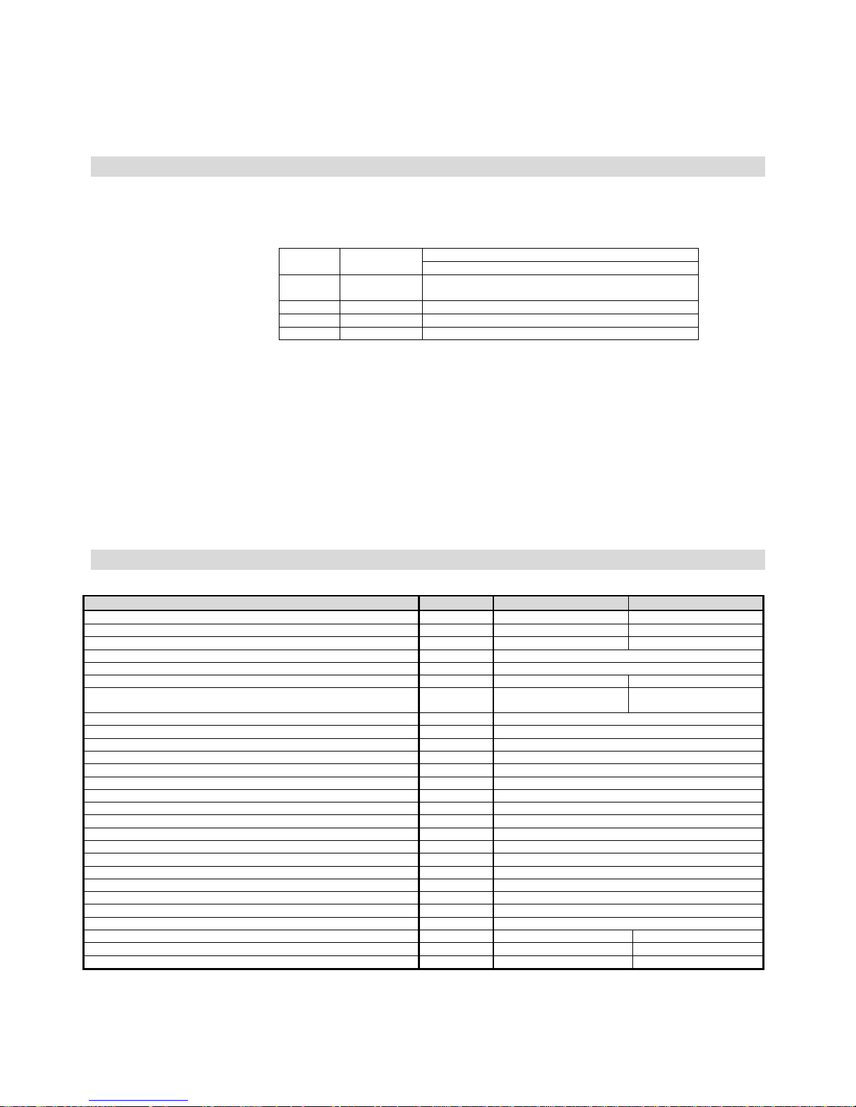
2 Technical data of the boiler
Tab. №. 1 Dimensions, technical parameters of the boiler
Boiler type A0C-X20P-00.16 A0C-X28P-00.16
Sections number pcs 5 7
Boiler weight (incl. the reservoir) kg 356 423
Water content l 40,9 81,3
Chimney throat diameter mm 156
Fuel reservoir capacity dm3 300
Boiler dimensions (incl. the reservoir): width x depth x high mm 1258 x 1207 x 1345 1258 x 1399 x 1345
Boiler dimensions (incl. the reservoir and the economizer):
width x depth x high
1258 x 1639 x 1345 1258 x 1833 x 1345
Receiving hopper capacity l 260
Diameter of the filling hole for manual filling mm 500
Diameter of the filling hole for automatic filling mm 50
Operation water overpressure kPa (bar) 400 (4)
Testing water overpressure kPa (bar) 800 (8)
Recommended operation heating water temperature °C 65 - 85
Minimum return water temperature °C 55
Cold water temperature °C 10
Overpressure for the safety heat-exchanger (DBV 1 – 02) bar 6
Boiler hydraulic loss (at ∆T 20 K) mbar 0,677
Hydraulic resistance coefficient 8,155
Noise level dB Not exceeding the level of 65 dB (A)
Chimney draught mbar 0,10 – 0,20
Boiler connections – heating water Js G 1 ½ “ (6/4“)
– return water Js G 1 ½ “ (6/4“)
Supply voltage 1/N/PE 230V AC 50 Hz TN - S
Electric cover IP 40
Electric energy consumption at the nominal power W 43 49
Electric energy consumption at the minimum power W 19 19
Electric energy consumption at the standby state W 2 2

4
Tab. №. 2 Heating technical parameters of the boiler
Boiler type A0C-X20P-00.16 A0C-X28P-00.16
Sections number pcs 5 7
Nominal power kW 20 28
Fuel consumption at the nominal power kg.h
-
1
4,9 6,7
Flue gases temperature at the nominal power - A0C-SXP/ A0C-AXP °C 211/113 154/109
Combustion time at the nominal power for the filled-up reservoir h 36 24
Minimum power kW 6,4 7,7
Fuel consumption at the minimum power kg/h 1,5 1,8
Flue gases temperature at the minimum power - A0C-SXP/ A0C-AXP
°C 114,5/74 96/70
Combustion time at the minimum power for the filled-up reservoir h 90 85
Minimum chimney draught mbar 0,14 0,14
Fuel heating power MJ.kg
-
1
16,78 16,78
Effectiveness - A0C-SXP/ A0C-AXP % 83,3/90 86,9/91,5
Mass flow rate of flue gases on the output side - A0C-SXP/ A0C-AXP
kg.s
-
1
0,014/0,014 0,018/0,017
Boiler class according to EN 303-5 - A0C-SXP/ A0C-AXP
4/5 4/5
Energy efficiency class A+ A+
Energy efficiency index - A0C-SXP/ A0C-AXP 107/114 113/117
Season energy efficiency - A0C-SXP/ A0C-AXP % 72/77 76/80
! Important warning:
The above specified heat technical parameters can be varied in dependence on a type, quality and humidity of the assessed fuel.
Values specified in table No. 1 and table No. 2 were measured during tests performed with usage of a prescribed fuel.
Pellets have to comply at least with one of the following directives and norms:
Directive No. 14-2000 of the Environmental Ministry of Czech Republic
DIN 517 31
ÖNORM M 7135
Prescribed pellet granulity 6 to 8 mm
Heating power 15 – 19 MJ.kg-1
Water content in fuel max. 12 %.
Ash content max. 1,5 %
WARNING! Bad fuel quality can dramatically negatively influence the output and emission parameters of the boiler.
Fig. №. 1 Boiler hydraulic loss
Power (kW)
Pressure loss pz (Pa)
5
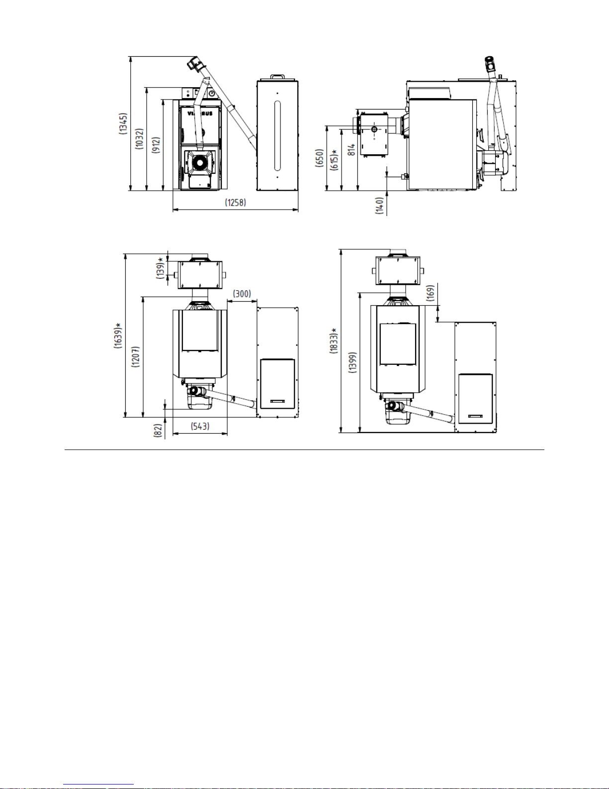
Fig. №. 2 Boiler main dimensions
VIADRUS A0C-S20P-00.16
*VIADRUS A0C-A20P-00.16
VIADRUS A0C-S28P-00.16
*VIADRUS A0C-A28P-00.16

6
3 Description
3.1 Boiler structure
The main part of the boiler is the sectional boiler drum made from grey cast iron according to EN 1561 grade 150.
Pressurized parts of the boiler complies with requirements for stiffness according to EN 303-5.
The boiler drum is assembled from sections by means of pressed boiler insertions and is fixed by anchor bolts. The sections create the heating
and ash space, the water space and the convection part. The heating water input and output are situated in the rear part of the boiler.
The rear section of the boiler has in its upper part a chimney pot and a heating water flange, in its bottom part has a return water flange with a
mouthpiece for a filling and draining cock. The cleaning and ash doors with an inbuilt burner are fixed to the front section.
The whole boiler drum is isolated by healthy mineral insulation, which decreases losses caused by heat transmission to the surroundings. The
steel cladding is painted by quality comaxite paint coat.
A pellet burner of PellasX is mounted in the ash door. In the version VIADRUS A0C-S20P it is a burner PellasX Hybrid mini, and in the version
VIADRUS A0C-S28P it is a burner PellasX Hybrid 35. These burners are equipped with a fan.
On the right (on the left) from the boiler it is placed a steel-sheet pellet reservoir with a capacity of 300 l. The reservoir is connected with the
burner by means of a feeder and a connecting hose.
An electric cabinet, in which the control unit and a display are situated, is mounted on the upper part of the cladding.
The unit is supplied in two versions. The S.Control with button control or the S.Control Touch with touch display.
1. Front section
2. Central section
3. Rear section
4. Stocking door (with a rosette of primary air)
5. Ash door
6. Chimney pot
7. Burner sealing
8. Burner PellasX
9. Connecting hose
10. Feeder
11. Reservoir
12. Cladding (complete)
13. Control cabinet
14. Regulator control elements (S.Control / Touch)
15. Heating water pipe
16. Ash-pan
17. Burner flange
18. Flange insulation
19. Return water pipe
20. Baffle
21. Upper insulation of the stocking door
22. Bottom insulation of the stocking door
23. Upper insulation of the ash door
24. Bottom insulation of the ash door
25. Securing valve
26. Burner pipe
27. Bushing
Fig. №. 3 Boiler main parts
7
Fig. №. 4 VIADRUS A0C-X20P - burner PellasX Hybrid
mini
Fig. №. 5 VIADRUS A0C-X28P - burner PellasX Hybrid 35
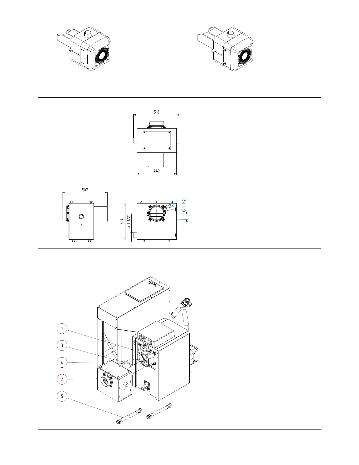
3.2 Economizer
Auxiliary equipment serving for getting the 5th emission class of the boiler.
Fig. №. 6 Economizer
3.2.1 Mounting of the economizer
Fig. №. 7 Mounting of the economizer
1. Boiler VIADRUS A0C
2. Economizer
3. Washer 8,4 (4 pcs)
4. Screw M8 x 20 (4 pcs)
5. Connecting hose
1. Put the economizer (2) on the chimney pot of the boiler
2. Screw up it with help of 4 pcs of the screws M8 (4) and the
washers 8,4 (4)
3. Connect the hose (5) and connect it to the output of the
economizer and to the return water pipe.

8
4 Placement and installation
4.1 Regulations and directives
The boiler complies with requirements of the following norms:
EN ISO 12100:2011 Safety of machine equipment – General principle for design – Assessment of risk and risk decreasing
EN 953+A1:2009 Safety of machine equipment – Protective covers – General requirements for design and production of firm and
movable protective covers
ČSN ISO 1819:1993 Equipment for continuous conveyance of loads. Safety rules. General provisions
ČSN ISO 11202:2010 Acoustics – Noise emitted by machines and equipment – Determination of levels of emission pressure on the
personnel working place and in other specified places with using of approximate corrections for environment
EN ISO 3746:2011 Acoustics - Determination of levels of acoustic power and levels of acoustic energy of noise sources by means of
acoustic pressure – Operation method with a measuring envelope above the reflective plane
EN 303-5:2013 Boilers for central heating - Part 5: Solid fuel boilers for central heating, with manual and automatic supply, with
nominal heat power up to 500 kW - Terminology, requirements, tests and marking
ČSN 061008:1997 Fire safety of heating equipment
EN 62233:2008 Measuring methods for electromagnetic fields for household and similar devices from the point of view of
exposition of persons
EN 60335 change A1 Safety of electric consumers for household and similar purposes. Part 1: General requirements
EN 15036-1:2007 Boilers for central heating – Testing rules for measurement of noise spread by air emitted by a heat source – Part
1: Emission of noise spread by air from heat sources
The boiler has to be only installed by a company which has authorization for performance of its installation and maintenance.
A project according to valid regulations has to be worked out for installation of the boiler.
The heating system has to be filled up by water, which complies with requirements of ČSN 07 7401, and mainly its hardness mustn’t
exceed the required parameters.
Tab. №. 3
Recommended values
Hardness mmol/l 1
Ca2+ mmol/l 0,3
Concentration of total Fe + Mn mg/l (0,3)*
*) recommended value
ATTENTION!!! The producer doesn’t recommend using of antifreezers.
a) for the heating system
ČSN 06 0310 Heat systems in buildings – Design and mounting
ČSN 06 0830 Heat systems in buildings – Securing devices
ČSN 07 7401 Water and steam for heat energetic equipment with steam operation pressure up to 8 MPa.
EN 303-5 Boilers for central heating – Part 5: Solid fuel boilers for central heating, with manual and automatic supply, with
nominal heat power up to 500 kW - Terminology, requirements, tests and marking.
b) for the chimney
ČSN 73 4201 Design of chimneys and flue gas ducts.
c) regarding to fire-fighting regulations
ČSN 06 1008 Fire safety of heat equipment.
EN 13501-1+A1 Fire classification of building products and building structures – Part 1: Classification according to results of tests
for reaction to fire.
d) for the hot water heating system
ČSN 06 0320 Heat systems in buildings – Preparation of hot water – Development and design.
ČSN 06 0830 Heat systems in buildings – Securing devices.
ČSN 75 5409 Inside water distributions
e) for electric network
ČSN 33 0165 Electric-technical regulations. Marking of conductors by colors or digits. Execution of provisions
ČSN 33 1500 Electric-technical regulations. Revisions of electric devices.
ČSN 33 2000-1 ed. 2 Low voltage electric installation – Part 1: Basic aspects, determination of basic characteristics, definitions
ČSN 33 2000-4-41 ed. 2 Low voltage electric installation – Part 4-41: Protective measures to ensure safety – Protection against electric
shock
ČSN 33 2000-5-51 ed. 3 Low voltage electric installation – Part 5-51: Selection and construction of electric devices – General regulations
ČSN 33 2130 ed. 2 Low voltage electric installation – Inside electric distributions
ČSN 33 2180 Electric-technical regulations. Connection of electric devices and consumers.
ČSN 34 0350 ed. 2 Safety requirements for movable power supplies and cords
EN 60079-10-1 Explosive atmospheres – Part 10-1: Determination of dangerous premises – Explosive gaseous atmospheres
EN 60079-14 ed.3 Explosive atmospheres – Part 14: Development, selection and performance of electric installations
EN 60252-1 ed. 2 Capacitors for AC motors – Part 1: In general – Fulfilment, testing, dimensioning – Safety requirements –
Instructions for mounting and operation.
EN 60335-1 ed.2 Electric consumers for household and similar purpose – Safety – Part 1: General requirements.
EN 60335-2-102 Electric consumers for household and similar purpose – Safety – Part 2-102: Special requirements for consumers
combusting gaseous, oil and solid fuels, containing electric connections.
EN 60445 ed. 4 Basic and safety principles for the human-machine interface, marking and identification – Identification of clamps
of subjects, ends of conductors and conductors
EN 61000-6-3 ed. 2 Electromagnetic compatibility (EMC) – Part 6-3: Generic norms – Emission – Residential, trade and light-industry
environment.
EN 61000-3-2 ed. 3 Electromagnetic compatibility (EMC) - Part 3-2: Limits – Limits for emission of harmonic currents (equipment with
input phase current <= 16 A).
EN 61000-3-3 ed. 2 (ed. 3) Electromagnetic compatibility (EMC) – Part 3-3: Limits – Limitation of changes of voltage, fluctuation of voltage
and flickers in low voltage distribution networks with the nominal phase current <= 16 A, which is not a subject of
conditional connection.
9
4.2 Possibility of placement
During boiler mounting and operation it is necessary to observe all requirements of ČSN 06 1008.
It is prohibited to place the boiler in a residential premise (including corridors)!
Placement of the boiler in the view of fire regulations:
1. Placement on the floor from inflammable material
− Install the boiler on an inflammable, heat-insulated basement exceeding the ground-plan of the boiler with the reservoir on sides by 20
mm.
− If the boiler is placed in a cellar, we recommend to install it on a supporting brickwork with the high at least 50 mm. The boiler has to
stay horizontally, possible unlevelnesses of the supporting brickwork are to be eliminated by means of a regulating screw of the motor
seat.
2. Safety distance from flammable materials
− During installation and at operation of the boiler it is necessary to observe a safety distance 200 mm from flammable materials with the
combustibility grade A1, A2, B and C (D);
− For lightly combustible materials with the combustibility grade E (F), which quickly burn and burn themselves even after removal of the
ignition source (for example, paper, paste-board, cardboard, asphalt- and tarboard, wood and fiberboards, plastics, floor cloths) the
safety distance is doubled, it means to 400 mm;
− The safety distance is to be also doubled in case when the grade of reaction to fire is not proven.
Tab. №. 4 Grade of reaction to fire
Grade of reaction to fire
Examples of building materials and products included in the reaction of fire
(extract from EN 13501-1+A1)
A1 – incombustible
Granite, sandstone, concrete, bricks, ceramic tiles, mortars, fireproof plasters,...
A2 – hardly combustible
acumin, izumin, heraklit, lignos, boards and basalt felt, fibreglass boards,...
B – heavily combustible
Beech and oak wood, hobrex boards, plywood, werzalit, umakart, sirkolit,...
C (D) – moderately combustible
Pinewood, larch, whitewood, chipboard and cork boards, rubber flooring,...
E (F) – lightly combustible
Asphaltboard, fibreboards, cellulose materials, polyurethane, polystyrene, polyethylene, PVC,...
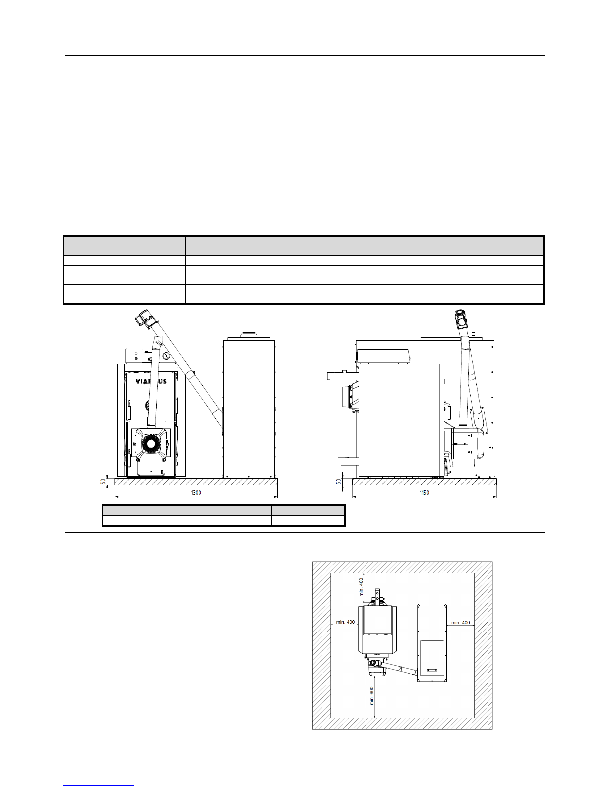
A0C-X20P-00.16 A0C-X28P-00.16
L [mm]
1150 1350
Fig. №. 8 Sizes of a supporting brickwork
Placement of the boiler with regard to a needed manipulation
space:
• basic environment AA5/AB5 according to ČSN 33 2000-1 ed. 2,
• in front of the boiler it is necessary to have a manipulation space
at least 600 mm,
• the minimum distance between the rear part of the boiler and a
wall 400 mm,
• on the side of the fuel reservoir – a gap at least
400 mm for a case of extraction of a feeding auger,
• the minimum distance from the side wall of the boiler 400 mm,
• above the boiler – at least 450 mm to enable cleaning-up of the
convection surface of the heat-exchanger.
Placement of the boiler with regard to an electric network:
• the boiler has to be placed so that the plug in the socket (230
V/50 Hz) was always accessible.
Fig. №. 9 Placement of the boiler in the boiler-room

10
Placement of fuel:
• For correct combustion in the boiler it is necessary to use dry fuel. The producer recommends to stock fuel in cellar premises or at
least under a penthouse,
• The producer recommends to observe distance between the boiler and fuel at least 1 000 mm, or place fuel to the room than the boiler.
It is necessary to provide constant supply of air for combustion and possible ventilation into the room where the boiler is installed (air
consumption of the boiler VIADRUS A0C-S20P is about 75 m3. h
-1
and the boiler VIADRUS A0C-S28P is about 105 m3. h-1). Connection of a
pipeline of the heating system, as well as an eventual pipeline of the heating insertion of the heater, has to be performed by an authorized
person.
WARNING: On connection of the boiler to the heating system it is necessary to place a discharging cock in the lowest place
and as close as it possible to the boiler.
5 Commissioning – instructions for contractual service organizations
Only contractual service organization authorized for performance of this activity has the right to perform commissioning of the
boiler.
5.1 Delivery and accessories content
The boiler VIADRUS A0C is supplied so that the complete boiler drum is situated on one pallet. The boiler cladding is packed separately.
Accessories laid inside the boiler drum are accessible after opening the cleaning door. The second pallet includes a burner, a fuel feeder and
their accessories. The boiler is packed in a transporting package and mustn’t be tripped during transportation; it is only allowed to incline to
sides to demount the package from the boiler drum.
Standard accessories:
• 1 pc boiler drum on a pallet with the corresponding number of sections
− 1 pc combustion space barrier – middle part
− 3 pcs combustion space barrier (A0C-X20P)
− 4 pcs combustion space barrier (A0C-X28P)
• 1 pc boiler drum cladding
− cladding insulation
− ash-pan with appropriate size
− holder for cleaning tools – type 2
• 2 pcs heating and return water pipe G 1 1/2"
• 1 pc cleaning tools - handle
• 1 pc pack
• 1 pc production label
• 1 pc control cabinet with electronics SControl/SControl Touch
• 1 pc burner PellasX according to a size
• 1 pc burner pipe
• 1 pc burner flange
• 3 pcs burner insulation
• 1 pc burner sealing
• 1 pc feeder PellasX
− 1 pc upper feeder pipe
− 1 pc bottom feeder pipe
− 1 pc feeder sealing
− 1 pc feeder motor
− 1 pc gear-box
− 1 pc sealing
• 1 pc manual for boiler operation and mounting
• 1 pc warranty certificate
• 1 pc list of contractual service organizations
The pack:
• 1 pc boiler plug G 1 1/2“ - blind
• 1 pc plug sealing Ø 60x48x2
• 2 pcs flange sealing 90 x 60 x 3
• 2 pcs door hinge
• 1 pc filling and discharging cock G 1/2“
• 1 pc manipulating wrench
• 1 pc brush
• 1 pc tip for piercer
• 1 pc handle 503a – 514
• 1 pc socket wrench with a handle - hexagonal 902-13
• 1 pc capillary spring
• 1 pc corrugated spring
• 1 pc thermowell
• connecting material:
− 5 pcs nut M8
− 3 pcs washer 8 (large-area)
− 12 pcs nut M10
− 4 pc washer 5,3
− 4 pc washer 6,4

11
− 2 pcs washer 8,4
− 12 pcs washer 10,5
− 4 pc connecting thorn
− 8 pc screw M5 x12
− 6 pc screw ST 4,2 x 9
− 4 pc spring clip
Obligatory accessories (it is not a part of supply):
• 1 pc securing valve according to max. operation overpressure of the boiler (see table No. 1)
On request:
• 1 pc outdoor sensor CT4 – P
• 1 pc room regulator ecoTOUCH
• 1 pc internet module NET CONTROL
• 1 pc securing valve
• 1 pc sensor CT4 – 4 m
• 1 pc reservoir
− 1 pc front metal sheet of the reservoir
− 1 pc rear metal sheet of the reservoir
− 1 pc right side metal sheet of the reservoir
− 1 pc left side metal sheet of the reservoir
− 1 pc upper metal sheet of the reservoir
− 1 pc reservoir leg
− 1 pc reservoir leg 2
− 1 pc reservoir cover
− 1 pc transversal part of the reservoir
− 1 pc feeder flange
− 1 pc hole cover
− 2 pcs reservoir brace
− 1 pc blind flange
− 1 pc transversal part 2 of the reservoir
• connecting material for the reservoir
− 2 pcs washer 5,3
− 2 pcs nut M5
− 2 pcs washer
− 9 pc screw ST 4,2 x 9,5 (ISO 7050)
− 4 pc screw ST 4,8 x 13
− 74 pc screw M5 x 12
− 2 pcs screw M6 x 12
− 1 pc piano hinge
− 1 pc handle
The boiler equipment ordered „on request“ is not included to the basic boiler price.
5.2 Mounting procedure
5.2.1 Boiler drum installation
1. Place the boiler drum onto the supporting brickwork.
2. Mount to the upper part of the rear boiler section the sealing φ 90 x 60 x 3 (1) and screw up the heating water flange (2), and connect the
other end to the heating system.
3. Mount to the bottom flange part of the rear boiler section the sealing φ 90 x 60 x 3 (5) and screw up the return water flange with a
mouthpiece (6) for a filling and discharging cock, and connect the other end to the heating system.
4. After connection the boiler to the heating system, screw up an elbow (9) with the filling and discharging cock into the mouthpiece of the
return water flange.
5. Screw up the thermostat well G 1/2“into the hole in the upper part of the rear section (see fig. 10).
Fig. №. 10 Thermowells mounting
6. Blind the hole with the thread Js 6/4" in the front section by a plug Js 6/4". Place sealing φ 60 x 48 x 2 under the plug.
7. Mount the chimney pipe to the chimney pot and insert it to the chimney hole.
1 Backward valve of the manometer
2 Thermostat well
 Loading...