

Page 1

I N D E X
1 Introduction................................................................................................................................... 1
2 Machine Dimension...................................................................................................................... 2
3 Safety Instruction.......................................................................................................................... 3
3-
1Warning labels............................................................................................................................ 3
3-
2 Safety devices of turning table & interlocking function of safety guard .................................. 4
3-
3 Safety guards............................................................................................................................. 5
3-
4 Moving elements....................................................................................................................... 6
3-
5 Safety related components......................................................................................................... 7
4 Installation of the machine............................................................................................................ 8
4-
1 Setting the machine and choosing base..................................................................................... 8
4-
2 Packing and Unpacking............................................................................................................. 8
4-
3 Handling and Transportation.................................................................................................... 10
4-
4 Installation of machine............................................................................................................. 11
4-
5 Assemble the Pre-stretch Unit.................................................................................................. 12
5 Control Panel................................................................................................................................ 13
5-
1 Description of key pad’s function on the control panel............................................................14
5-
2 Wrapping function control........................................................................................................ 16
5-
3 Status indication....................................................................................................................... 18
5-
4 Breakdown indication............................................................................................................... 20
5-
5 Motion indication.......................................................................................................... ...........21
6 Film Loading................................................................................................................................ 23
7 Film Tension Adjust.....................................................................................................................24
8 Operation Procedure .................................................................................................................. 25
9 Maintenance................................................................................................................................. 26
9-
1 Installing and removing turntable ............................................................................................ 26
9-
2 Adjusting tightness of turntable chain...................................................................................... 27
10 Electrical .................................................................................................................................... 28
10-1 Parts list of electrical components...................................................................................... 28
10-2 EMC component list........................................................................................................... 33
10-3 Electrical wiring diagram ................................................................................................... 34
11 T roubleshooting..........................................................................................................................46
11
-1-1 Power indication hasn’t lighted on...................................................................................... 46
11
-1-2 There isn’t DC12 Volt. On power supply PD-25A ............................................................. 47
Page 2

11
-1-3 There isn’t DC24 Volt. On power supply PS-65-24............................................................ 48
11
-2-1 Turntable motor not operating (Inverter) ............................................................................ 49
11
-2-2 Turntable motor Speed not adjustable................................................................................. 49
11
-3-1 Film-seat motor brake (BK2) not working.......................................................................... 50
11
-3-2 Film-seat elevator motor not rising..................................................................................... 51
11
-3-3 Film-seat elevator motor not rising..................................................................................... 52
11
-4 Film-seat doesn’t stop when reached package limit ............................................................. 53
11
-5 Film-seat doesn’t pause.......................................................................................................... 53
11
-6-1 Film-seat doesn’t stop after reaching maximum packaging limit....................................... 54
11
-6-2 Film-seat doesn’t stop after returning to starting position.................................................. 54
11
-6-3 Film-seat motor speed not adjustable ................................................................................ 55
11
-7-1 Turntable hasn’t slowed down before completing wrapping cycle..................................... 55
11
-7-2 Turntable doesn’t stop after completing wrapping cycle.................................................... 56
11
-8 LS1, LS2, PS1, PS2 & PH not operating normally on PC board KS-050202-key ................ 56
11
-9 Control panel buttons not working......................................................................................... 57
11
-10 Pre-stretch motor M3 hasn’t worked.................................................................................... 58
12 Machine parts diagram............................................................................................................... 60
13
-1-1 Fig-11000 Pillar parts diagram............................................................................................61
12
-1-2 Fig-11000 Pillar parts table ............................................................................................... 62
12
-2-1 Fig-12000 Film-seat elevator parts diagram....................................................................... 65
12
-2-2 Fig-12000 Film-seat elevator parts table ............................................................................ 66
12
-3-1 Fig-14000 Bottom plate diagram........................................................................................ 67
12
-3-2 Fig-14000 Bottom plate parts table..................................................................................... 68
12
-4-1 Fig-18000 Control box diagram.......................................................................................... 70
12
-4-2 Fig-18000 Control box table............................................................................................... 71
12
-5-1 Fig-18100 Control box diagram.......................................................................................... 74
12
-5-2 Fig-18100 Control box table............................................................................................... 75
12
-6-1 Fig-19000 Pre-Stretch Unit diagram................................................................................... 76
12
-6-2 Fig-19000 Pre-Stretch Unit table........................................................................................ 77
12
-7-1 Fig-19100 Pre-Stretch Unit diagram................................................................................... 82
12
-7-2 Fig-19100 Pre-Stretch Unit table........................................................................................ 83
13 Parts list...................................................................................................................................... 84
Page 3

1 Introduction
Thank you for purchasing a state-of-the-art SHII-MEEI stretch film pallet wrapping machine.
All of us at SHII-MEEI would like to express our gratitude, and our desire to continue serving you
in the best possible way.
Please read all the instructions in this User’s Guide before attempting to operate the machine.
This will enable you to operate the machine safely and at peak efficiency. We have made every
effort to ensure that all information in this Guide is up to date. However, our commitment to
continuously improve all our products may result in you receiving a machine that does not conform
exactly to these instructions. Since we are quick to take advantage of new technology as it becomes
available, we must reserve the right to change our products and User’s Guide without prior notice.
All our distributors are fully knowledgeable about all aspects of our products. If you have any
need for advice or service, please do no hesitate to call upon them.
F:\Manual\SM-1517R-110V-100514 14.05.2010.
- 1 -
Page 4
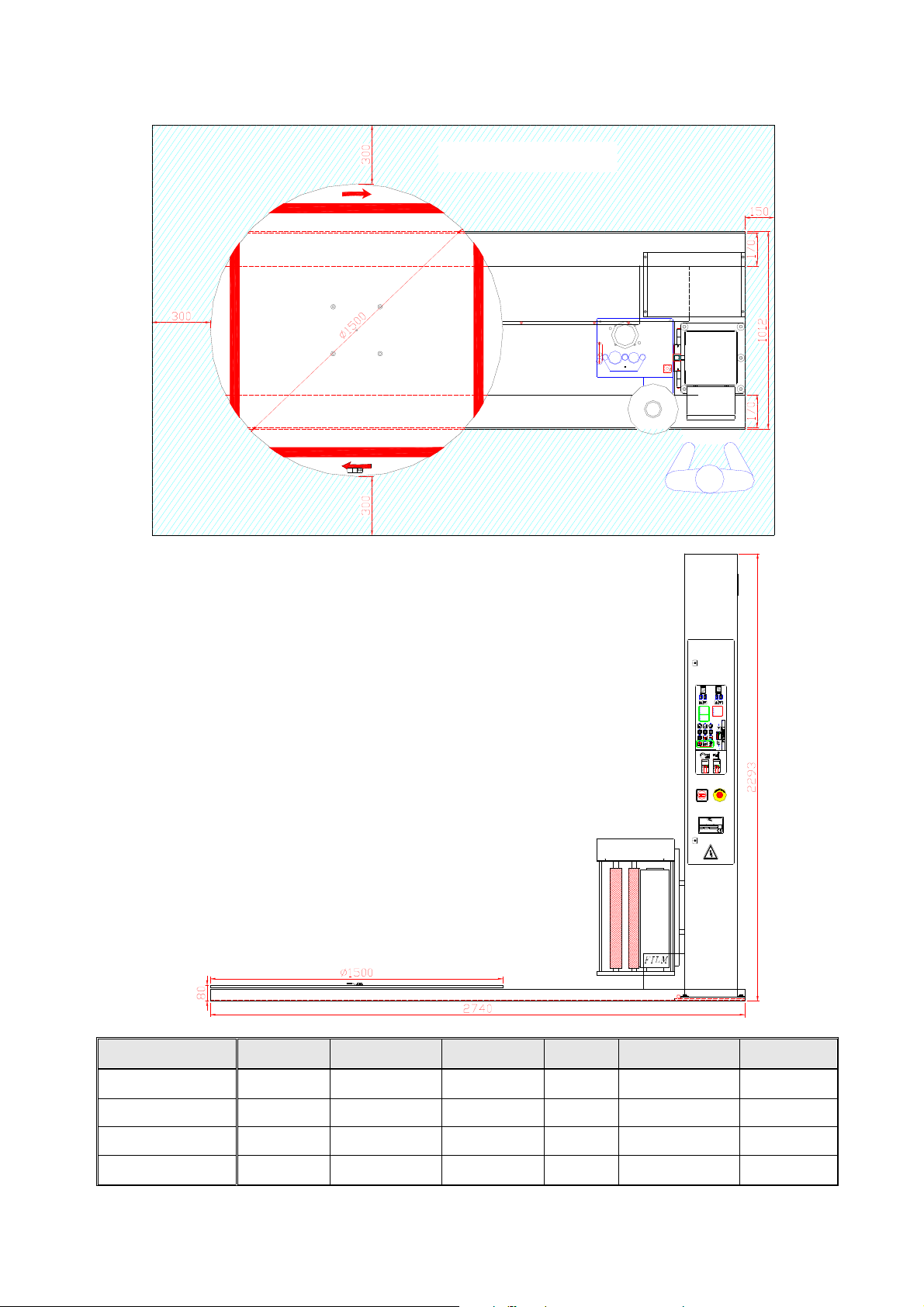
2 Machine Dimension
Clearance area
FILM
CONTROL
BOX
Missionary
Power
Stand By (AUTO)
Film Seat Zero Return
Turntable Zero Return
Film Cut
Turntable Slow Down
For SM-2517 Only
Follower-Plate Up
LS3-Up
Follower-Plate Down
LS4-Down
12
5
4
87
PS2
MODE
ENTER
FREQ. SET
LC-M2E
l ON
F
F
O
0
STRETCH WRAPPING MACHINE
ITEM NO.
SM-
AIR
bar
SHII MEEI INDUSTRIAL CO., LTD.
26, Sec. 1, Ta Fu Road, Tan Tzu Hsiang,
Taichung Hsien, Taiwan, R.O.C.
TEL:886 4 533−6601
Breakdown Indicator
No Film (SM-1517R)
M1 Motor Trip-Out
M2 Motor Trip-Out
Emergency Stop
BK2 Fail
BK2 Fuse Fail
M2
BK2
LS1
M3
3
PH
6
LS2-2
9
LS2-1
LS2
M1
PS1
DIGITAL KEYPAD
DIGITAL KEYPAD
RUN
RUN
MODE
STOP
STOP
ENTER
RESET
RESET
VFD-M
VFD-M
FREQ. SET
LC-M2E
R
SERIES NO. POWER
A
Hz
V
WEIGHT
DATE
Phase
Kgs.
FAX:886 4 533−6776
Model L W H H1 Turntable Weight
SM-1517R 2,740mm 1,500mm 2,293mm 80m/m Ø 1,500mm 530kg
SM-1517R -18 3,100mm 1,800mm 2,293mm 80m/m Ø 1,800mm 580kg
SM-1517R-20 3,300mm 2,000mm 2,293mm 80m/m Ø 2,000mm 630kg
SM-1517R-23 3,500mm 2,300mm 2,293mm 80m/m Ø 2,300mm 680kg
F:\Manual\SM-1517R-110V-100514 14.05.2010.
- 2 -
Page 5

3 Safety Cautions
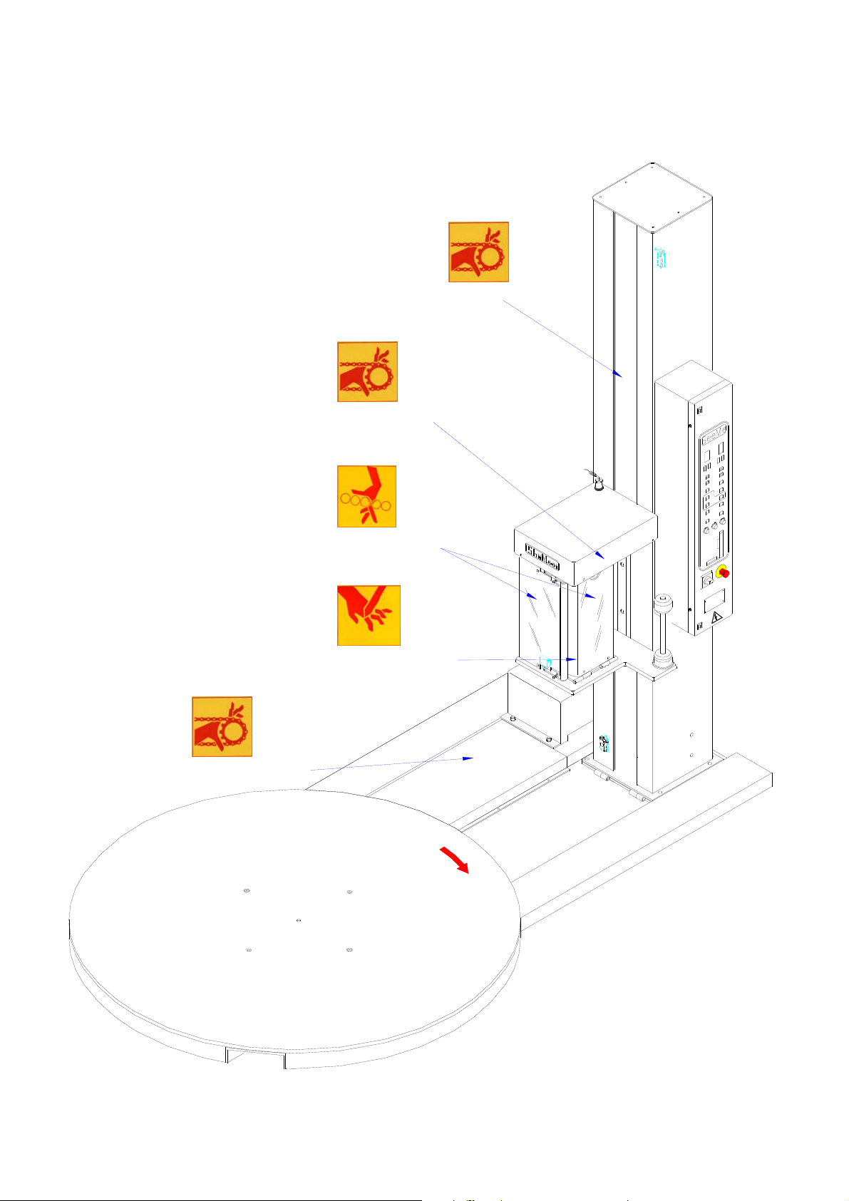
3-1 Warning labels
Dangerous Location Precaution Marking Label
Dangerous Area and Working Environment
The dangerous location is inside the
control panel.
The dangerous location is inside the
right and left rising & descending
columns.
The dangerous location is in motor
reduction gear head.
Dangerous location is on the driving
rollers of the pre-stretch unit. So, we
have stuck the label on the fixed guard
Hazardous voltage. Turn power off
before open the panel.
Keep hand, cloths and body clear of
the rotating chain. If hand tangled into
the chain and sprocket can cause
severe injury.
Keep hand, cloths and body clear of
the rotating gears. If hand tangled into
the gears can cause severe injury.
Drawing-in hazard caused by driving
rollers.
of the rollers.
The dangerous location is on the tape
cutter
Keep hand away from the cutter. If
hand placed under the cutter and the
cutter move downward can cause
severe injury.
F:\Manual\SM-1517R-110V-100514 14.05.2010.
- 3 -
Page 6

3-2 Safety devices of turning table & interlocking function of safety guard
Buttons of emergency stop are SB1 which would disconnect to main power and SB2 which would
disconnect to controller.
SB1
SB2
Power disconnect
Controller PCB input
F:\Manual\SM-1517R-110V-100514 14.05.2010.
- 4 -
Page 7
3-3 Safety guards
Fixed guard for chain
Fixed guard for chain
Fixed guard for roller
Fixed guard for knife
Fixed guard for chain
F:\Manual\SM-1517R-110V-100514 14.05.2010.
- 5 -
Page 8
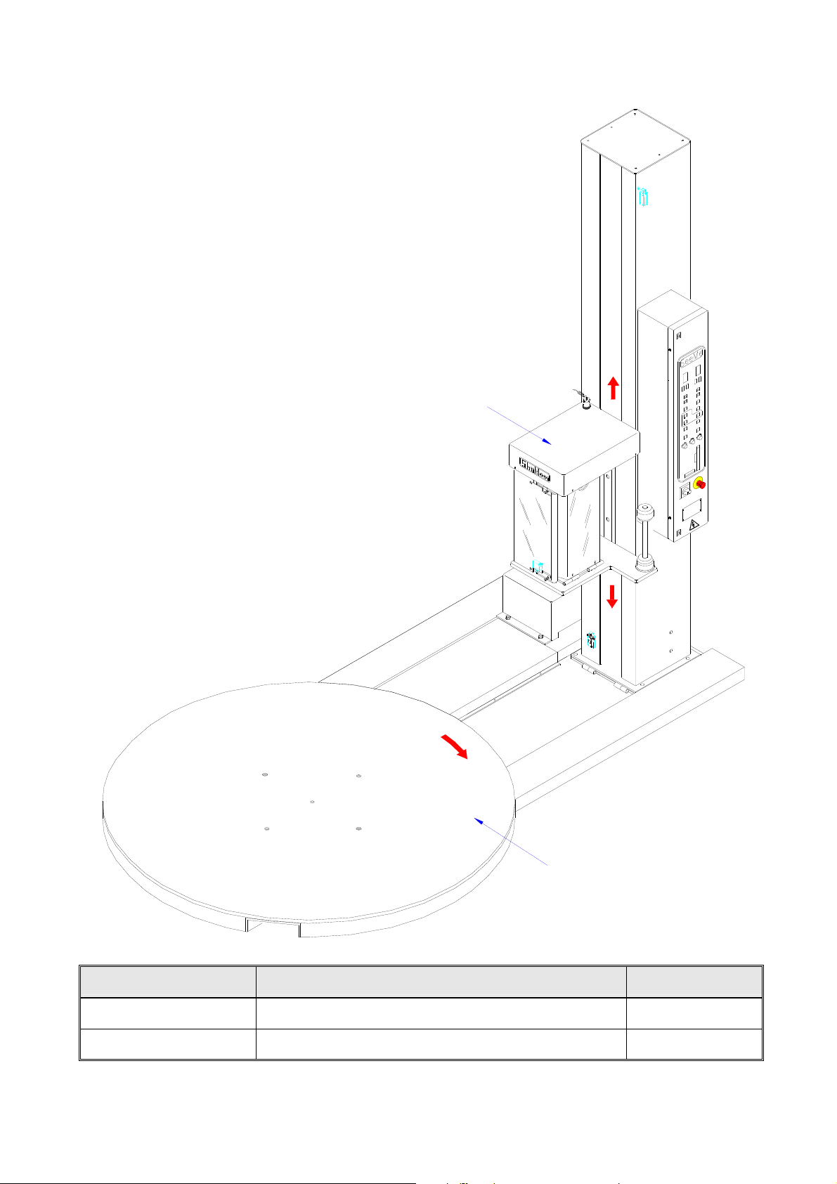
3-4 Moving elements
Pre-Stretch Unit
Turntable
Moving parts name Movement Power source
Pre-Stretch Unit Up or down Motor
Turntable Up to open, down to close Motor
F:\Manual\SM-1517R-110V-100514 14.05.2010.
- 6 -
Page 9
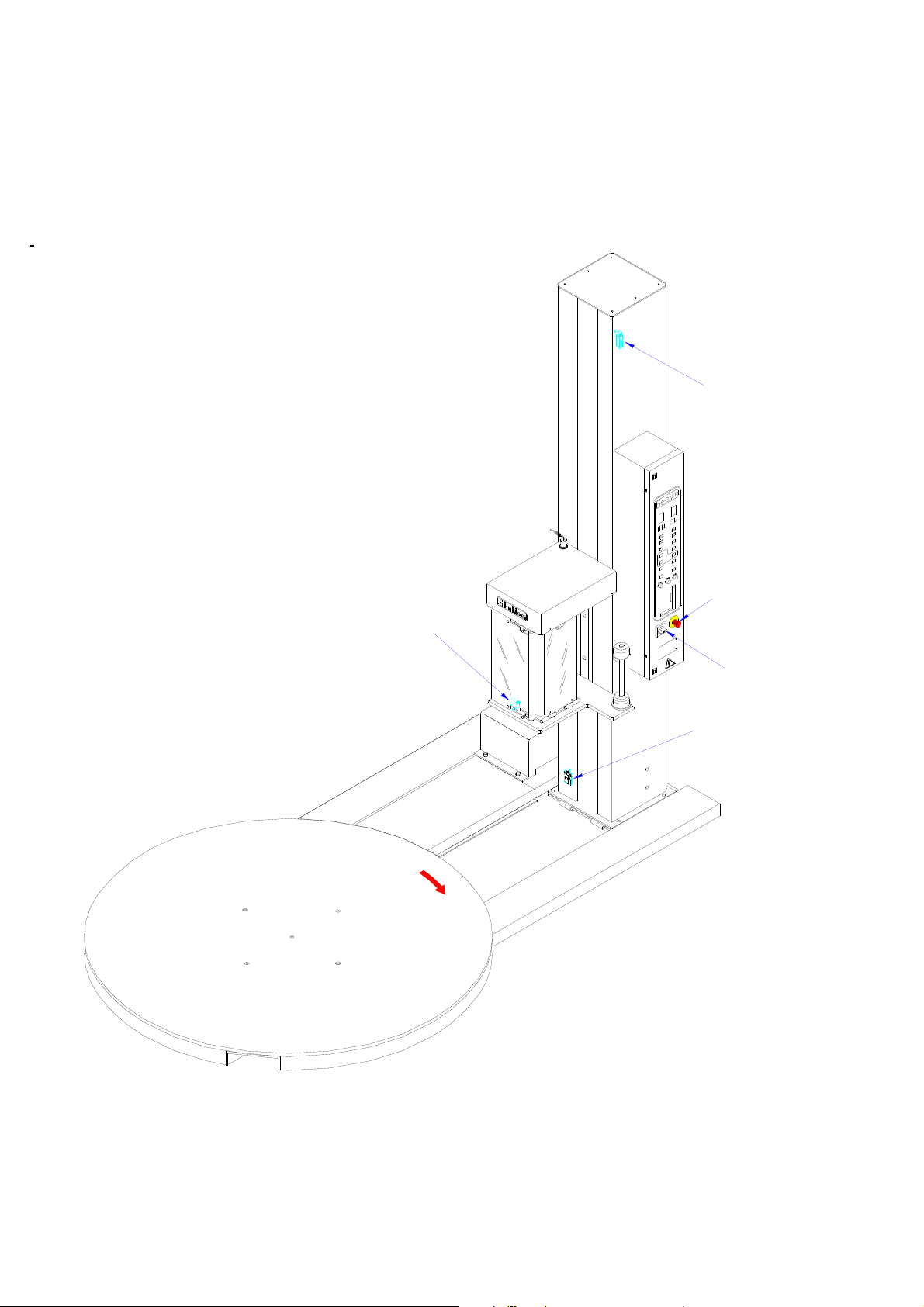
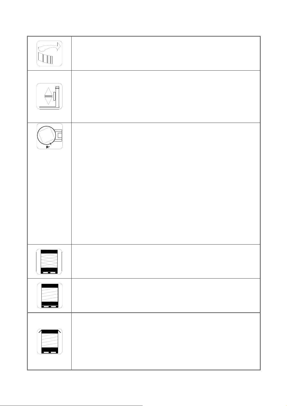
3-5 Safety related components
Upper limit switch
Lower limit switch
Emergency stop button
Main power switch
Lower limit switch
F:\Manual\SM-1517R-110V-100514 14.05.2010.
- 7 -
Page 10
4 Installation of the machine
4-1 Setting the machine and choosing base
1. The site for the machine should provide the conditions essential for precision installation,
2. If the machine is placed on an upper floor, it shall ensure that the floor has adequate
strength for this machine.
3. A clear area must be provided along the rear face of the machine in accordance with the
diagram forward in page 2 and it is essential for efficient maintenance and assembly.
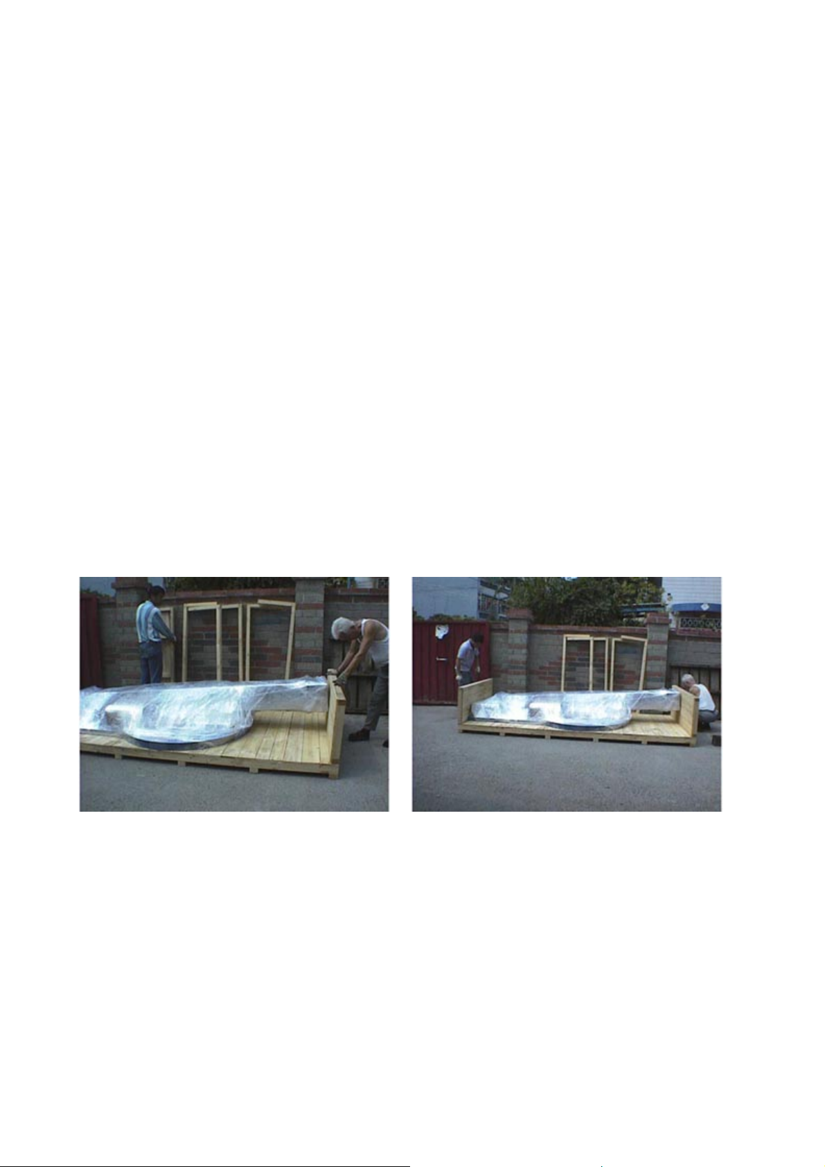
4-2 Packing and Unpacking
1. In general, the machine was packed with carton and pallet. The processes are as follows:
2. Please refer to machine weight in page 2 to arrange handling equipment.
3. Before unpacking always keep the mark Ï (or “up” arrow sign) upward and keep the
packing away from impact for preventing any damage on the machine.
4. Remove top portion first. Then, remove the side portions.
5. Do not damage any components inside the carton.
6. About the packing procedures, please refer to the following illustration diagrams.
7. The unpacking procedure is the reversal of packing.
1. Firstly, fix the side portion. Reserve the gap between the column and the side portion for
minimum 1 cm.
2. Fix the opposite side portion.
F:\Manual\SM-1517R-110V-100514 14.05.2010.
- 8 -
Page 11
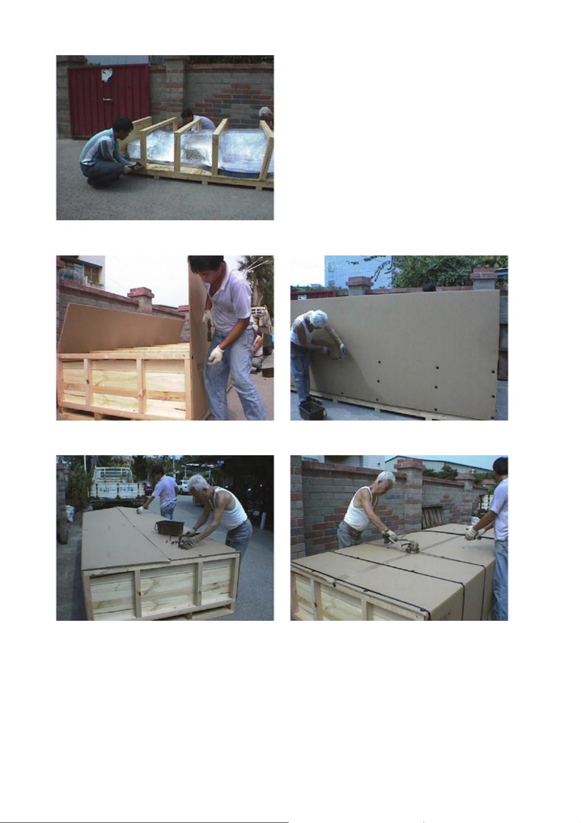
3. Fix the supporting frames.
4. Put and fix the side carton.
5. Fold the carton to cover the top and fix by nails with plastic washers.
6. Tighten the pack with steel strips.
F:\Manual\SM-1517R-110V-100514 14.05.2010.
- 9 -
Page 12
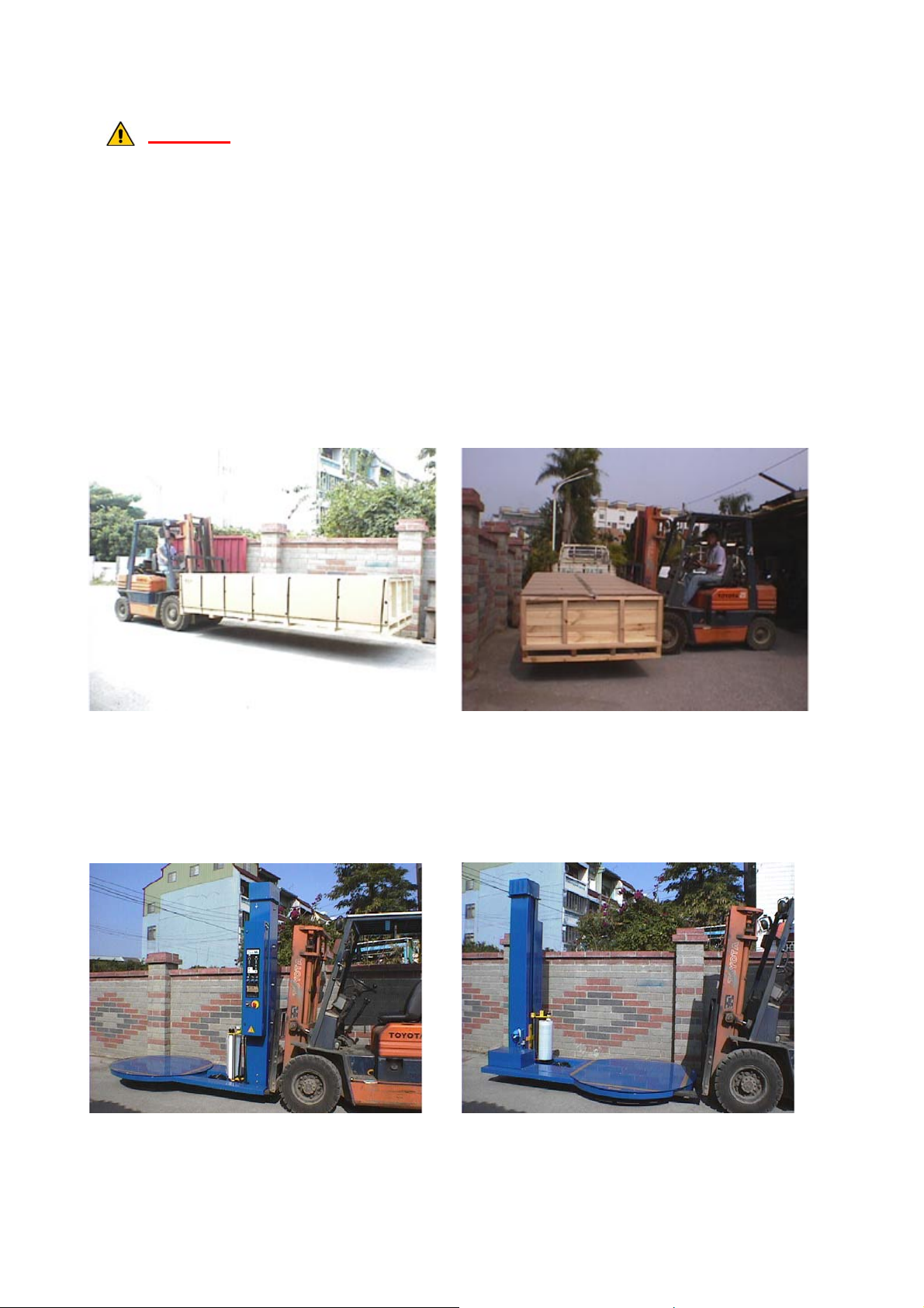
4-3 Handling and Transportation
Caution!
The machine shall be moved by persons who are qualified. Persons exclude the
operators are not allowed to stay in the work place during transporting the machine.
1. Please refer to machine specifications to arrange handling equipment. Be sure to use capable
fork-lifter to lift of machine.
2. The handling and transportation shall be carried out by qualified persons.
3. Forklift that used in handling the machine shall be operated by a qualified driver.
4. Before handling, make sure all movable parts are secured in their positions and all movable
accessories should be removed from machine.
5. During handling, people are strictly prohibited from entering into the path of machine
movement.
6. While transportation, keep attention to the balance of machine.
7. As the fork position, please refer to the diagrams shown below.
Fig.1 Fig.2
For machine pack transportation:
1. If the machine pack is transported from the narrow side, the fork length used on the forklift
should be more than 2.2 m. (as shown in the illustration diagram Fig.1)
2. If the machine pack is transported from the wide side, the fork length used on the forklift should
be more than 1 m. (as shown in the illustration diagram Fig.2)
Fig.3 Fig.4
For machine handling, please do it according to that shown in the illustration diagram Fig.3 and
Fig.4
F:\Manual\SM-1517R-110V-100514 14.05.2010.
- 10 -
Page 13

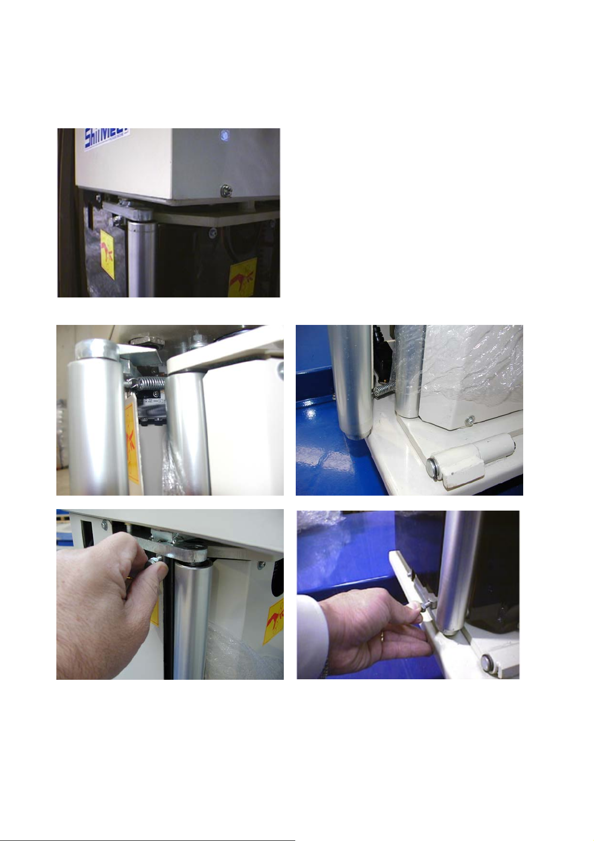
4-4 Installation of machine
1. First fix an eye end screw on the top of Pillar. 2. Hook the chain on the eye end.
3. Attached the chain or steel cable on a fork lift.
Get five M5X25 screws ready from the tool box.
5. Slowly move back the fork lift until the Pillar
is up around 80 degree to the ground.
4. Rise the fork up around 2m high,
6.Push the Pillar until it is right up.
7. Use 5 M12×25 Socket head screws with
washers to tight up the Pillar on the base. Be
sure those 5 screws have been fastened securely.
F:\Manual\SM-1517R-110V-100514 14.05.2010.
- 11 -
Page 14
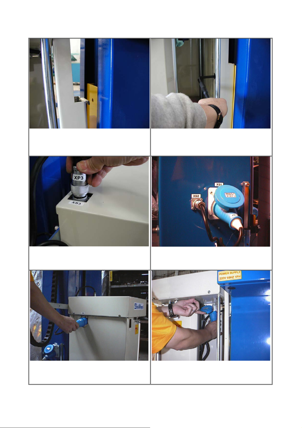
4-5 Assemble the Pre-stretch Unit
Place the M12 x 55 bolts into place and hook the
pre-stretch unit onto the film seat.
Connect XP3 onto XS3 and tighten.
Make sure bolts are tightened onto the film seat
to secure the pre-stretch unit and ensure safe
operation.
Connect XP1 onto XS1.
Extend connection point XP4 through the
Connect XP4 onto XS4.
pre-stretch unit.
F:\Manual\SM-1517R-110V-100514 14.05.2010.
- 12 -
Page 15
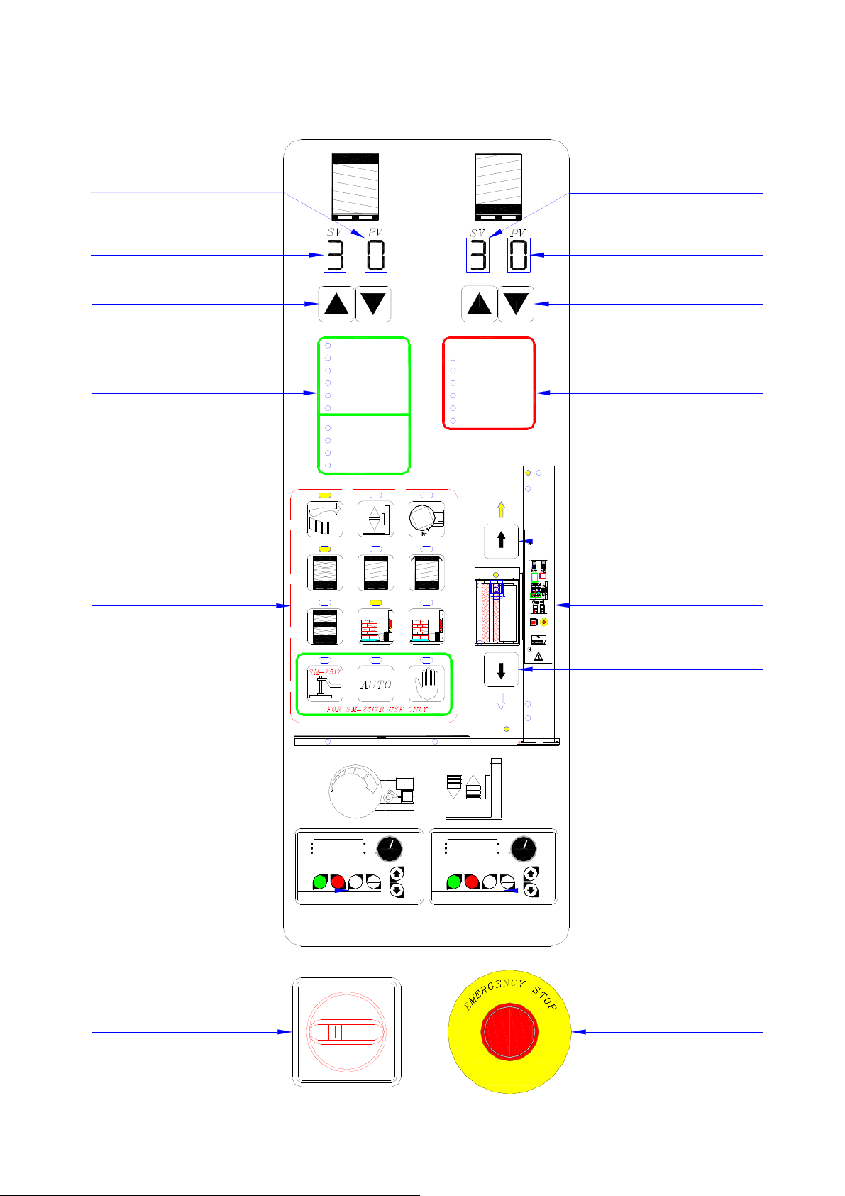
5 Control Panel
No. of Upper Layers Counted
No. of Upper layers Set
Cycle Setting of Upper layer
No. of Lower Layers Counted
No. of lower Layers Set
Cycle setting of Lower layer
Status Indication
Wrapping Function Control
Power
Stand By (AUTO)
Film Seat Zero Return
Turntable Zero Return
Film Cut
Turntable Slow Down
For SM-2517 Only
Follower-Plate Up
LS3-Up
Follower-Plate Down
LS4-Down
1 32
465
7
PS2
89
PS1
Breakdown Indicator
No Film (SM-1517R)
M1 Motor Trip-Out
M2 Motor Trip-Out
Emergency Stop
BK2 Fail
BK2 Fuse Fail
M3
PH
LS2-2
M1
LS2-1
Breakdown Indicator
BK2
M2
LS1
Pre-stretch Unit Carrier Ascent Key
Power
Breakdown Indicator
Stand By (AUTO)
No Film (SM-1517R)
Film Seat Zero Return
M1 Motor Trip-Out
Turntable Zero Return
M2 Motor Trip-Out
Film Cut
Emergency Stop
Turntable Slow Down
BK2 Fail
For SM-2517 Only
BK2 Fuse Fail
Follower-Plate Up
LS3-Up
Follower-Plate Down
LS4-Down
M2
BK2
LS1
M3
1
23
PH
564
LS2-2
7 98
LS2-1
LS2
M1
Motion Indication
PS2
PS1
l ON
F
F
O
0
STRETCH WRAPPING MACHINE
SERIES NO.
ITEM NO.
POWER
A
SM-
Hz
V
WEIGHT
DATE
AIR
Phase
Kgs.
bar
SHII MEEI INDUSTRIAL CO., LTD.
FAX:886 4 533−6776
TEL:886 4 533−6601
Pre-stretch Unit Carrier Descent Key
LS2
Turntable Speed Adjustment
RUN STOP
FWD
REV
PROG
PROG
RUN
MODE
RUN
DATA
DATA
VFD-e
PROG
DATA
RUN STOP
FWD
REV
PROG
PROG
RUN
MODE
RUN
DATA
DATA
VFD-e
PROG
DATA
Film-seat Speed Adjustment
l ON
F
Power Switch
F:\Manual\SM-1517R-110V-100514 14.05.2010.
F
O
0
- 13 -
Emergency Stop Button
Page 16

5-1 Description of Key pad’s function on the control panel
No. of Upper Layers Counted:
Displays the number of completed upper layer wrapping cycles. Screen should be blank prior to
start of wrapping cycle. When wrapping cycle begins, for each completed upper layer wrapping
cycle the number increases by 1. When number of upper layers counted reaches the number of
upper layers set, the film-seat will start descending.
No. of Upper Layers Set:
Displays the number of wrapping cycles set for the upper layer.
Cycle Setting of Upper Layer:
Sets the number of upper layer wrapping cycles. Press “▲” once increases wrapping cycle by 1 and
press “▼” decreases wrapping cycle by 1. Wrapping cycle can be set to 9 as maximum, however
usually is set between 2-5 depending on different needs. Please note that wrapping cycle can not be
set to 0, as to lengthen the life span of the elevation motor.
No. of Lower Layers Counted:
Displays the number of completed lower layer wrapping cycles. Screen should be blank prior to
start of wrapping cycle. When wrapping cycle begins, for each completed lower layer wrapping
cycle the number increases by 1. When number of lower layers counted reaches the number of
lower layers set, the film-seat will start ascending.
No. of Lower Layers Set:
Displays the number of wrapping cycles set for the lower layer.
Cycle Setting of Lower Layer:
Sets the number of lower layer wrapping cycles. Press “▲” once increases wrapping cycle by 1 and
press “▼” decreases wrapping cycle by 1. Wrapping cycle can be set to 9 as maximum, however
usually is set between 2-5 depending on different needs.
Status Indication:
For detail, refer section 5-3.
Breakdown Indication:
For detail, refer section 5-4.
Wrapping Function Control:
For detail, refer section 5-2.
F:\Manual\SM-1517R-110V-100514 14.05.2010.
- 14 -
Page 17

Motion Indication:
For detail, refer section 5-5.
Turntable Speed Adjuster:
Turntable speed can be adjusted between 0-13rpm. This function should be used in conjunction
with the Film-seat Speed Adjuster, refer to Film-seat Speed Adjuster section for more detail.
Film-seat Speed Adjuster:
Film-seat speed can be adjusted between 0~3m/min, either quicken or slower film-seat elevation
speed for desired level of film overlap. When wrapping a test package, adjust turntable speed to
maximum 13rpm and film-seat to maximum 3m/min, then when wrapping completes study the level
of film overlap for further adjustment. If a higher level of film overlap is desired, slower the
film-seat speed; if a lower level of film overlap is desired, slower the turntable speed.
Power Switch:
Main power switch with a safety device. When switch is turned "ON", the switch will jam the
control panel door and prevent it from being opened to provide safety. Please note that if the control
panel door is to be opened this switch must be turned "OFF", or else if the door is forced open when
switch is at "ON" position, the switch will break. If the power switch is broken in such a manner, it
can not be replaced free of charge even if still under warranty.
Emergency Stop Button:
In case of emergency, press this button to stop the operation of the machine and the power will
automatically be turned off. Pull this button to deactivate the emergency stop.
Pre-stretch Unit Ascent Key:
This key is used to manually control the pre-stretch unit to ascent while the machine has stopped.
Press this key; the pre-stretch unit will go up. Release it, the pre-stretch unit will stop immediately.
Pre-stretch Unit Descent Key:
This key is used to manually control the pre-stretch unit to descent while the machine has stopped.
Press this key; the pre-stretch unit will go down. Release it; the pre-stretch unit will stop
immediately.
F:\Manual\SM-1517R-110V-100514 14.05.2010.
- 15 -
Page 18
5-2 Wrapping Function Control
b
『Turntable Start』:
Starts the turntable rotation, motor will stop automatically when wrapping is
completed.
『Film-Seat Pause Button』:
When wrapping a particular section of the package that needs extra overlapping
of film to give strength, press and hold this button for the film-seat to pause at
the desired section of overlapping. When the operator is satisfied with the
amount of overlapping, release this button and the film-seat will continue its
ascending/descending.
『Turntable and Film-seat Zero-return Button』:
This button has two functions:
1: It can be used to determine the height of package in case of malfunctioning
of the electronic eye. When electronic eye malfunctions, the film-seat can not
sense the height of the package and will continue to ascend, in which case by
pressing this button the film-seat will cease ascending and start counting number
of upper layer wrapping cycles. Also press this button if the film wrapping
reaches a particular height of the package and further more wrapping above is
not desired.
2: If the emergency button is activated during wrapping, the turntable and the
film-seat will not be stopped at the starting position. Therefore in order for both
the turntable and the film-seat to return to their starting position, press this
utton once for turntable to return to starting position and press again for
film-seat to return to starting position.
『Standard Wrapping』:
Film starts wrapping from the bottom of the package to the top, and once from
top back to bottom。
『Single Layer Wrapping』:
Film wraps once from bottom to top and stops when turntable comes to a halt.
Film set then automatically descends down to starting point.
『Water Proof Wrapping』:
Film wraps from bottom to top and then comes to a halt at
approximately 10cm~15cm below the top of the package, then a sheet of water
proofing film or plastic should be manually placed on top of the package. Press
the Turntable Start button once more to restart the wrapping process, at which
the film will start wrapping from top back to bottom.
F:\Manual\SM-1517R-110V-100514 14.05.2010.
- 16 -
Page 19

『Midpoint Strengthen Wrapping』:
Film wraps from bottom to top and completes the upper layer wrapping cycle.
When returning from top back to bottom, film set will pause at the midpoint of
the package to complete 2 wrapping cycles and then back to bottom to
complete wrapping.
『Auto cut option』:
l ON
0 OFF
To choose the auto cut option.
『Non-auto cut option』:
l ON
0 OFF
R
STRETCH WRAPPING MACHINE
ITEM NO.
POWER
SERIES NO.
SM-
V
A
Hz
DATE
AIR
WEIGHT
Phase
Kgs.
bar
SHII MEEI INDUSTRIAL CO., LTD.
26, Sec. 1, Ta Fu Road, Tan Tzu Hsiang,
Taichung Hsien, Taiwan, R.O.C.
TEL:886 4 533−6601
FAX:886 4 533−6776
To choose the non-auto cut option.
For SM-2517 & SM-2517R Use only
『Follower-Plate Fall Down Button』:
To lower the follower-plate, used in conjunction with the 『Auto 』&
『Manual』buttons. When set at 『Auto』, press this button to lower
follower-plate onto package until tight, after which the follower-plate stops
lowering and turntable rotation starts. If set at 『Manual』, press this button to
lower follower-plate to stop lowering follower-plate. There is need to press
the Turntable 『Start』button to start turntable rotation when using 『Manual』
function..
『Auto』Wrapping Modes Setting Key:
When this function is set the button will light up. Press the “Follower-plate
Down” button when this function is activated, the follower-plate will
automatically lower onto package until tight and turntable rotation will start.
When wrapping cycle is completed, the follower-plate will lift up again. No
need to press any other button.
『Manual』Wrapping Modes Setting:
When this function is set, press the “Follower-plate Down” button to lower the
follower-plate and limit switch LS4 is touched to stop lowering. The turntable
will not start automatically, therefore press “Turntable Start” button to start
turntable rotation.
F:\Manual\SM-1517R-110V-100514 14.05.2010.
- 17 -
Page 20

5-3 Status Indication
Power
Stand By (AUTO)
Film Seat Zero Return
Turntable Zero Return
Film Cut
Turntable Slow Down
For SM-2517 Only
Follower-Plate Up
LS3-Up
Follower-Plate Down
LS4-Down
○Power Pilot
When LED light is on, the power is at the “ON” status; when LED light is off, the power is at the
“OFF” status.
○Stand By (AUTO)
The machine is in standby status.
○Film Seat Zero Return:
The film carrier is descending back to the Zero point.
○Turntable Zero Return:
The turntable is rotating back to the Zero point.
○Film Cut
The machine is breaking the film,
○Turntable Slow Down
The turntable is slowing down,
○Follower-Plate Up
The Follower-Plate is ascending,
○LS3-Up
LS3 is the (Zero point) limit switch: If this light on indicates the “Follower-Plate” has ascended
back to the Zero Point. If the “Follower-Plate” has not back to the Zero Point the machine will not
be operated.
F:\Manual\SM-1517R-110V-100514 14.05.2010.
- 18 -
Page 21

○Follower-Plate Down
The Follower-Plate is descending,
○LS4-Down
If this light on, indicates the “Follower-Plate” has clamped the package tight and the
“Follower-Plate” will be stopped. If this light has not on, the machine will not be operated.
F:\Manual\SM-1517R-110V-100514 14.05.2010.
- 19 -
Page 22

5-4 Breakdown Indication
Breakdown Indicator
No Film (SM-1517R)
M1 Motor Trip-Out
M2 Motor Trip-Out
Emergency Stop
BK2 Fail
BK2 Fuse Fail
○No Film:
Indicates no film; only SM-1517Rhas this function.
○M1 Motor Trip-Out:
The M1 motor is overloaded and its breaker jumped.
○M2 Motor Trip-Out:
The M2 motor is overloaded and its breaker jumped.
○Emergency Stop:
Emergency Stop Indicator, When the LED light is on, the emergency stop button is currently being
activated.
○BK2 Fail:
The BK2 electrical Break has failed.
○Bk2 Fuse Fail:
The fuse of the BK2 electrical Break has failed.
F:\Manual\SM-1517R-110V-100514 14.05.2010.
- 20 -
Page 23
5-5 Motion Indication
M2
BK2
LS1
M3
PH
Power
Breakdown Indicator
No Film (SM-1517R)
Stand By (AUTO)
M1 Motor Trip-Out
Film Seat Zero Return
M2 Motor Trip-Out
Turntable Zero Return
Emergency Stop
Film Cut
BK2 Fail
Turntable Slow Down
For SM-2517 Only
BK2 Fuse Fail
Follower-Plate Up
LS3-Up
Follower-Plate Down
LS4-Down
M2
BK2
LS1
M3
3
2
PH
6
514
LS2-2
987
LS2-1
LS2
M1
PS2
PS1
l ON
F
F
O
0
R
STRETCH WRAPPING MACHINE
SERIES NO.
ITEM NO.
POWER
A
SM-
Hz
V
WEIGHT
DATE
AIR
Phase
Kgs.
bar
SHII MEEI INDUSTRIAL CO., LTD.
26, Sec. 1, Ta Fu Road, Tan Tzu Hsiang,
Taichung Hsien, Taiwan, R.O.C.
TEL:886 4 533−6601
LS2-2
FAX:886 4 533−6776
LS2-1
LS2
M1
PS2
PS1
M2 Motor Ascending and Descending Indicator
If this LED light is on indicates the M2 motor is in operation, the pre-Stretch Unit is ascending or
descending.
LS1 Upper Limit Safety Switch Indicator
If this LED light is on, indicates the package has over the packing height limit of this machine or
the PH (height detecting optical sensor) has failed; please check if the package height has over the
limit or PH sensor has failed.
M3 Pre-Stretch Unit Motor Indicator
When the turntable is starting to rotate and the film pulls the free roller, this light will be on and the
film will start to be sent out from the Pre-Stretch Unit; if this LED light is not on, the film will not
be sent out from the Pre-Stretch Unit.
PH Height Detecting Optical Sensor Indicator
When PH has detected the package, this LED light will not be on. Once the film carrier ascend and
the PH sensor can not detect the package, this light will be on and the film carrier stop.
LS2-2 Pre-Stretch Unit Safety Switch Indicator
This switch is parallel link with the LS2 (lower Limit Safety Switch). When this LED light is on
F:\Manual\SM-1517R-110V-100514 14.05.2010.
- 21 -
Page 24

indicates the Pre-Stretch Unit has descended to the lower limit or the Pre-Stretch Unit has pressed
any object and the turntable will be stopped.
LS2-1 Lower Limit Switch Indicator
When this LED light is on indicates the Pre-Stretch Unit has descended to the bottom position and
the Pre-Stretch Unit will stop to descend.
LS2 Lower Limit Safety Switch Indicator
This switch is parallel link with the LS2-2 (Pre-Stretch Unit Safety Switch). When this LED light is
on indicates the Pre-Stretch Unit has descended and over the bottom of the machine or the LS2-1
has failed. Please check the LS2-1 switch.
M1 Turntable Motor Indicator
This LED light on indicates M1 (Turntable Motor) is operating and the turntable is rotating.
PS1 Allocation and Counter Indicator
When the turntable completes a rotation, this LED light will flash once. Therefore this indicator
expresses two functions: a counter and an indication of a complete rotation.
Counting Function:
When the turntable completes a rotation this indicator will flash once and the counter number will
be increased by one until the rotation number has reach the pre-set wrapping number. After that,
although the turntable completes one rotation and this indicator will still flash once, however the
counter number will not be increased.
Allocation Function:
When PS2 (Slow Stopping Indicator) flashes once, the turntable will start to slow down, once the
PS1 indicator flashes the turntable will be stopped immediately. This indicator’s light will be on to
indicate the turntable has stopped at the zero point.
PS2 Slow Stopping Indicator
When the LED light of LS2-1 is on, once the turntable passed the PS2 switch, the light of the “PS2
Slow Stopping Indicator” will flash once and the turntable will start to be slowing down until the
turntable has fully stopped.
Pre-Stretch Unit Ascending Indicator
This LED light on indicates the Pre-Stretch Unit is ascending.
Pre-Stretch Unit Descending Indicator
This LED light on indicates the Pre-Stretch Unit is descending.
F:\Manual\SM-1517R-110V-100514 14.05.2010.
- 22 -
Page 25
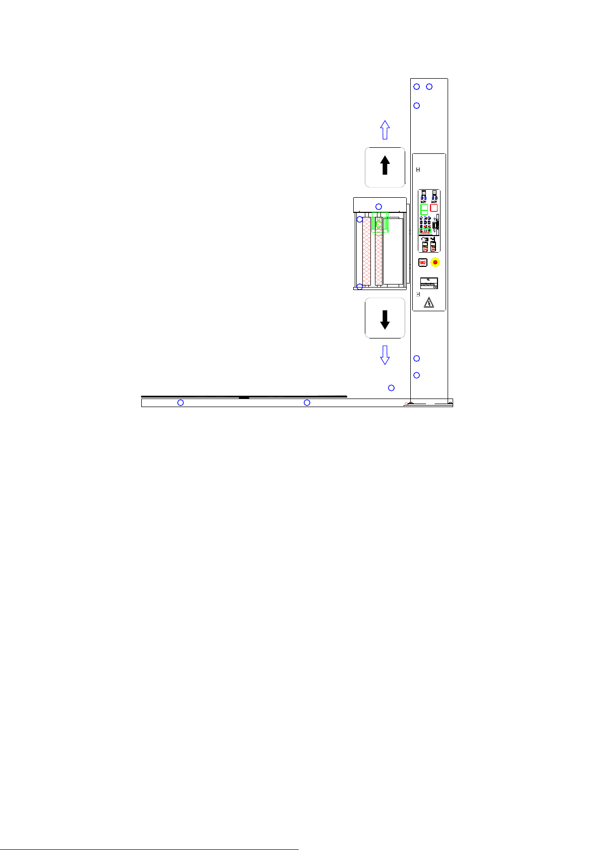
6 Film Loading (For safety please switch off main power when loading film.)
1. Pull out approx. 60cm of film in counter-
Clock direction.
3. Pull down film seat cover lock.
2. Place film into film seat.
4. Open film seat cover.
5. Pull out film between film seat cover And
film seat rollers.
6. Have at least 20-30cm of film out through
between film seat cover and rollers.
7. Close film seat cover and switch on power
to start operation.
F:\Manual\SM-1517R-110V-100514 14.05.2010.
- 23 -
Page 26
7 Film Tension Adjust
The pre-stretch unit has a set pre-stretch percentage of 240% (can not be changed) which is
called the First Stage Pre-stretch, therefore there is no pre-stretch setting device on the control panel.
The pre-stretch percentage can be slightly adjusted to a maximum of 320%, which is called the
Second Stage Pre-stretch, and its adjusting method is shown below:
There are 2 sets of nuts and bolts located on the top and bottom of the free roller and is used to
adjust pre-stretch ratio.
Pull away the free roller and 2 springs can be seen attached to the 2 sets of nuts and bolts.
Slightly tighten the nuts onto the bolts to pull on the springs in order to increase pre-stretch ratio.
Warning: Do not pull on free roller while pre-stretch unit in operation, as not to cause film
jamming into rollers.
F:\Manual\SM-1517R-110V-100514 14.05.2010.
- 24 -
Page 27

8 Operation Procedure
1.
Turn power switch to "ON" position.
2.
Set number of upper and lower layer cycles.
3.
Set film tension.
4.
Set film-seat speed.
Pull out a small length of film and tie to pallet or to hook
5.
on turntable.
6.
Press start button.
7.
To continue wrapping, just repeat steps 5 and 6.
F:\Manual\SM-1517R-110V-100514 14.05.2010.
- 25 -
Page 28

9 Maintenance
9-1 Installing and removing turntable
Firstly remove the 4 fixing screws from the
turntable, then screw on the 2 lifting devices
onto turntable perpendicularly.
Use one of the forklift’s forks to penetrate
the lifting devices.
Lift the turntable up and away from the
machine to begin maintenance and service.
F:\Manual\SM-1517R-110V-100514 14.05.2010.
- 26 -
Page 29

9-2 Adjusting tightness of turntable chain
In case of turntable chain becoming loose.
1. Use a 6mm L shape spanner, in counter-clockwise direction, loosen the two M8 bolts.
2. Use a 14mm open spanner, in clockwise direction, turn the M14 nut to tighten the chain.
3. Similar to step 1, use a 6mm L shape spanner to tighten the two M8 bolts in clockwise
direction.
4. Put little amount of grease oil on the chain and the six turntable supporting wheels.
F:\Manual\SM-1517R-110V-100514 14.05.2010.
- 27 -
Page 30

10 Electrical
10-1 Part list of electrical components
Item
designation
SP1 Switching power
SP2 Switching power
SP3 Switching power
KS-050201-MB Controller Kai Shun KS-050201-MB DC-5V
KS-050202-KEY Key board pcb Kai Shun KS-050202-KEY DC-5V EN61000-4-5
KS-050203-TB Terminal block pcb Kai Shun KS-050203-TB DC-5V,12V,24V EN61000-4-5
Description &
function
supply, supply dc
power to controller
supply, supply dc
power to sps1
supply, supply dc
power to brake
Manufacture Type Technical data Complies with the
following standards
Mean Well PD-25A Ue=240VAC
OUT1:DC5V 2.1A
OUT2:DC12V1.2A
Mean Well NES-15-24 Ue=240VAC
OUT:DC 24V 1A
Mean Well PS-65-24 Ue=240VAC
OUT:DC 24V 2.7A
6MHZ
EN61000-4-5,EN60950 CE,TUV
EN60950,EN61000-4-5 CE
EN60950,EN61000-4-5 CE
EN61000-4-5
ENV50204
ENV50204
Marking of
conformity granted
CE
CE
CE
ENV50204
MPSW1 Power switch ABB OT25E3 Ue=750VAC
Ith=32A
AC-23A=20A
LF Line filter Hi & Lo 20SS4-1BC2-B Ue=250VAC
Ith=20A
F:\Manual\SM-1517R-110V-100514 14.05.2010.
- 28 -
EN60204
IEC 947/1,3
IEC60947
E134751 CE
CE
Page 31

Item
designation
MS Protected inverters
Description &
function
Manufacture Type Technical data Complies with the
Iskra MS25-20 Ue=750VAC
and motors
IVR1 Inverter, controls
DELTA VFD007E11A Ue=115VAC
motor1’s speed
IVR2 Inverter, controls
DELTA VFD004E11A Ue=115VAC
motor2’s speed
IVR3 Inverter, controls
DELTA VFD004E11A Ue=115VAC
motor3’s speed
FAN Heat sink
PROFANTEC
P1082HST Ue=115VAC 0.14A EN 61000-3-2
E-STOP Emergency stop T.E. ZA5BT4/
10
F1
Fuse, Protected the
DEMEX FM04L-B/1A Ue=250V
Icu=100KA
Ie=20A
0.75KW
0.40KW
0.40KW
Ue=400VAC
Ith=10A
Marking of
following standards
EN60947-2
conformity granted
CE,UL,CSA
EN60947-4-1
EN60204-1
EN50178,
CE,UL
EN61800-3
EN50178,
CE,UL
EN61800-3
EN50178,
CE,UL
EN61800-3
CE,UL
IEC 801-4
EN60947-1,EN60947-5-1 CE,UL,CSA
CE 947.3 CE.UL
cutter of solenoid
Ith=10A
FUSE=1A
F2 Fuse, Protected the
cutter of solenoid
DEMEX FM04L-B/1A Ue=250V
Ith=10A
CE 947.3 CE,UL
FUSE=1A
F3 Fuse, Input ac
power to switching
power sp1,sp2
F:\Manual\SM-1517R-110V-100514 14.05.2010.
DEMEX FM04L-B/3A Ue=250V
Ith=10A
FUSE=3A
- 29 -
CE 947.3 CE,UL
Page 32

Item
designation
F4 Fuse, Input ac
LS1 Upper limit switch COCA AZ-8108 Ue=240VAC Ith=5A EN60947-5-1
Description &
function
power to switching
power sp1,sp2
Manufacture Type Technical data Complies with the
following standards
DEMEX FM04L-B/3A Ue=250V
CE 947.3 CE,UL
Ith=10A
FUSE=3A
conformity granted
CE
EN81
EN115
LS2 Lower limit switch COCA AZ-8104 Ue=240VAC Ith=5A 73/23/EEC CE
LS2-1 Lower limit switch COCA AZ-8104 Ue=240VAC Ith=5A 73/23/EEC CE
LS2-2 Lower limit switch OMRON Z-15GQ22-B Ue=250VAC
EN 60947-1 CE,VDE,UL
Ith=15A
PS1 Proximity
sensor
PS2 Proximity
sensor
TEND TP-SM-5N1 Ue=30VDC
Iout=150mA 4m/m
TEND TP-SM-5N1 Ue=30VDC
Iout=150mA
EN 50082-2,
EN61000-3-2
EN 50082-2,
EN61000-3-2
CE
CE
Marking of
4m/m
PH Photo Sensor FOTEK FR-2MX Ue=30VDC
Iout=150mA
EN50082-1
IEC802-1
IEC801-3
EN55011
SPS1 Proximity
sensor
PULSO 9914-0900 Ue=30VDC
Iout=10mA
EN 50010 CE
IP67
F:\Manual\SM-1517R-110V-100514 14.05.2010.
- 30 -
CE
Page 33

Item
designation
M 1 Motor
M 2 Motor
M 3 Motor
Description &
function
Manufacture Type Technical data Complies with the
following standards
ADLEE Co.,
Ltd.
T.G.P.Co 3~AC 230VAC
Liming Co.,
Ltd.
3~AC 230VAC
0.75kW
0.2kW
3~AC 230VAC
0.2kW
Ue=220VAC
EN60034-1 CE
IP55
Ue=220VAC
EN60034-1 CE
IP54
xxx
Marking of
conformity granted
BK2 Brake for motor2 T.G.P.Co. SBV-063 DC24V EN60034-1 CE
XS1 Connector
STARHL
CP00401627 Ue=380VAC
CEI23-12/VII CE
Ith=16A
4 POLES IP67
XP1 Connector
STARHL
CP11401627 Ue=380VAC
CEI23-12/VII CE
Ith=16A
4 POLES IP67
XS2 Connector APEX CO. PLS-207-RF -------
XP2 Connector APEX CO. PLS-207-PM -------
XS3 Connector APEX CO. PLS-207-RM -------
XP3 Connector APEX CO. PLS-207-PF -------
XS4 Connector
STARHL
CP01301624
Ue=220VAC
Ith=16A
CEI23-12/VII CE
3 POLES IP54
F:\Manual\SM-1517R-110V-100514 14.05.2010.
- 31 -
Page 34

Item
designation
XP4 Connector
Description &
function
Manufacture Type Technical data Complies with the
following standards
STARHL
CP20301624 Ue=220VAC
CEI23-12/VII CE
Marking of
conformity granted
Ith=16A
3 POLES IP54
TB9,TB11 Terminal block ENTRELEC D4/6 UE=660VAC
EN60847-1 CE
Ith=27A
TNR1 TNR MARCON 15G471K Ue=300VAC 80J. ------
F:\Manual\SM-1517R-110V-100514 14.05.2010.
- 32 -
Page 35

10-2 EMC Component List
Item Name Specification Refer to ckt. diagram Approved document
1 MOTOR1 3~ 0.75KW AC220V SM-1517R: P.1
2 MOTOR2 3~ 0.2KW AC220V SM-1517R: P.1
3 MOTOR3 3~ 0.2KW AC
220V
4 LINE FILTER 20SS4-1BC2-B
20A AC250V
5 INVERTER1 VFD007E-11A
0.75KW AC 115V
6 INVERTER2 VFD004E-11A
0.4KW AC 115V
7 INVERTER3 VFD004E-11A
0.4KW AC 115V
9 SWITCHING POWER
SUPPLY
10 SWITCHING POWER
SUPPLY
11 MAIN POWER
SWITCH
PD-25A DC5V SM-1517R: P.1 EMC-P.5
PS-65-24 DC24V
2.7A
OT25E3 Ith=32A
AC 250V
SM-1517R: P.5
SM-1517R: P.1 EMC-P.1
SM-1517R: P.1 EMC-P.2
SM-1517R: P.1 EMC-P.2
SM-1517R: P.5 EMC-P.2
SM-1517R: P.1 EMC-P.5
SM-1517R: P.1 EMC-P.6
12 PC BOARD KS-050201-MB SM-1517R: P.2, P.3 EMC-P.7
13 PC BPARD KS-050202-KEY SM-1517R: P.2 ,P.3,P4 EMC-P.7
14 PC BPARD KS-050203-TB SM-1517R: P.5 EMC-P.7
15 SWITCHING POWER
SUPPLY
16 FAN 3-115S
17 PROXIMITY
SENSOR
NES-15-24 DC 24V
0.7A
115VAC 0.07A
TP-SM5N1 DC30V SM-1517R: P.7 EMC-P.11
SM-1517R: P.5, P.7 EMC-P.8
SM-1517R: P.1 EMC-P.10
F:\Manual\SM-1517R-110V-100514 14.05.2010.
- 33 -
Page 36

10-3 Electrical Wiring Diagram
F:\Manual\SM-1517R-110V-100514 14.05.2010.
- 34 -
Page 37

F:\Manual\SM-1517R-110V-100514 14.05.2010.
- 35 -
Page 38

F:\Manual\SM-1517R-110V-100514 14.05.2010.
- 36 -
Page 39

F:\Manual\SM-1517R-110V-100514 14.05.2010.
- 37 -
Page 40

F:\Manual\SM-1517R-110V-100514 14.05.2010.
- 38 -
Page 41

F:\Manual\SM-1517R-110V-100514 14.05.2010.
- 39 -
Page 42

F:\Manual\SM-1517R-110V-100514 14.05.2010.
- 40 -
Page 43

F:\Manual\SM-1517R-110V-100514 14.05.2010.
- 41 -
Page 44

F:\Manual\SM-1517R-110V-100514 14.05.2010.
- 42 -
Page 45

F:\Manual\SM-1517R-110V-100514 14.05.2010.
- 43 -
Page 46

F:\Manual\SM-1517R-110V-100514 14.05.2010.
- 44 -
Page 47

F:\Manual\SM-1517R-110V-100514 14.05.2010.
- 45 -
Page 48

11 Troubleshooting
When problem with machine occurs, please check if power input is of correct voltage and
check that power supply PD-25A is outputting DC5V and DC12V and check that power supply
PS-65-24 is outputting DC24V ..
11-1-1 Power indication hasn’t lighted on
Refer to PC board KS-050201-MB, check
if there’s DC5V at P1 and P2 on CN1.
Refer to PC board PD-25A, check if there’s
DC5V at P1 and P2 on CN2.
Check if FUSE F1 on PC board PD-25A is
blown.
Refer to PC board PD-25A, check if there’s
AC220V at P1 and P2 on CN1.
Check if there’s AC110V at terminal L12
and L22.
NO
NO
NO
NO
YES Replace PC board KS-050202-KEY
and connection cord CN2
YES
Replace connection cord CN1.
YES
Replace FUSE.
YES
Replace PC board PD-25A.
YES
Replace FUSE F3 and F4(3A).
Check if there’s AC110V at terminal L12
and L22.
Check if input power voltage is normal.
F:\Manual\SM-1517R-110V-100514 14.05.2010.
NO
NO
YES
YES
- 46 -
Replace Line Filter.
Replace Main Power Switch.
Page 49

11-1-2 There isn’t DC12 Volt. on power supply PD-25A
Refer to PC board KS-050201-MB, check
if there’s DC12V at P3 and P4 on CN1.
NO
Refer to PC board PD-25A, check if there’s
DC12V at P3 and P4 on CN2.
NO
Check if FUSE F1 on PC board PD-25A is
blown.
NO
Refer to PC board PD-25A, check if there’s
AC220V at P1 and P2 on CN1.
NO
Check if there’s AC110V at terminal L12
and L22.
YES
Replace connection cord CN11
YES
Replace connection cord CN1.
YES
Replace FUSE.
YES
Replace PC board PD-25A.
YES
Replace FUSE F3 and F4(3A).
NO
Check if there’s AC110V at terminal L11
and L21.
NO
Check if input power voltage is normal.
YES
Replace Line Filter.
YES
Replace Main Power Switch.
F:\Manual\SM-1517R-110V-100514 14.05.2010.
- 47 -
Page 50

11-1-3 There isn’t DC24 Volt. on power supply PS-65-24
Refer to PC board PS-65A, check if there’s
DC24V at P1 and P4 on CN2.
Check if FUSE F1 on PC board PS-65A is
blown.
Refer to PC board PS-65A, check if there’s
AC220V at P1 and P2 on CN1.
Check if there’s AC110V at terminal L12
and L22.
Check if there’s AC110V at terminal L11
and L21.
NO
NO
NO
NO
YES
Replace connection cord CN9.
YES
Replace FUSE.
YES
Replace PC board PS-65A.
YES
Replace FUSE F3 and F4(3A).
YES
Replace Line Filter.
Check if input power voltage is normal.
NO
YES
Replace Main Power Switch.
F:\Manual\SM-1517R-110V-100514 14.05.2010.
- 48 -
Page 51

11-2-1 Turntable motor not operating (Inverter)
Condition:
a.) LED M1 is lighting up on PC board KS-050202-KEY.
b.) Emergency Stop is normal and does not be activated.
c.) Variable resister VR1 has been normal and has been turned to maximum position.
d.) There’s AC110V at terminal R and T on Inverter IVR1.
e). Touch Start key and start LED light up.
Check if there’s AC220V at outputs U,V
and U,W and V,W on Inverter IVR1.
Refer to Inverter IVR1, short terminal MI1
and DCM with a wire. Check if the motor M1
is working.
Replace Inverter IVR1.
NO
NO
YES
YES
11-2-2. Turntable motor speed not adjustable
Replace motor M1.
Replace PC board
KS-050201-MB.
Check if Variable resister VR1 is working.
Check if Inverter IVR1 is working.
NO
YES
YES
Check if Inverter IVR1 is working.
Check if Inverter IVR1 is working.
F:\Manual\SM-1517R-110V-100514 14.05.2010.
- 49 -
Page 52

11-3-1 Film-seat motor brake (BK2) not working
Condition:
a). Relay RYBK2 is working on PC board KS-050201-MB and LED BK2 would light up.
b). Fuse F1 (2A) on PC board KS-050201-MB is normal. (If a fuse F1 was blown, red LED BK2
Fuse fail on PC board KS-050202-KEY would light up.)
Check if brake B2+ and B2- contain
DC24V.
NO
Check if there’s DC24V at terminal 0V and
24V of CN9 on PC board KS-050201-MB.
NO
Refer to1-3, check if switching power
PS-65-24 is working.
YES
Replace brake BK2.
YES
Replace Relay RYBK2
F:\Manual\SM-1517R-110V-100514 14.05.2010.
- 50 -
Page 53

11-3-2 Film-seat elevator motor not rising
f
Condition:
a). LED M2 is lighting up on PC board KS-050202-KEY. IC OP1 has controlled elevator rising.
b). Relay RYBK2 is working, LED BK2 on PC board KS-050202-KEY and LD26 on PC board
KS-050201-MB are lighting up. Relay RYBK2 has controlled brake BK2 working.
c). Brake BK2 is working.
d). LED MD and MD1 can’t work at the same time when LED MU and MU1 are working.
e). There’s AC110V at terminal R and S terminal on Inverter IVR2.
f). Emergency Stop is normal and does not activate.
g). Variable resister VR2 has been normal and has been turned to maximum
position.
Check if there’s AC220V at outputs U,V
and U,W and V,W on Inverter IVR2.
Refer to Inverter IVR2, short terminal MI1
and DCM (ascending) with a wire. Check if
the display screen on Inverter changes and
motor M2 is working.
Refer to Limit Switch LS1, short Terminal
Block TB2 at terminal MU and MU1 with a
wire on PC board KS-0502030-TB. Check if
the display screen on Inverter changes and
motor M2 is working.
Refer to Limit Switch LS1, short Terminal
NO
YES
NO
YES
Replace Motor M2.
NO
Replace Inverter IVR2.
YES
Replace Limit Switch LS1.
Block TB2 at terminal MU and MU1 with a
wire on PC board KS-0502030-TB. Check i
the display screen on Inverter changes and
motor M2 is working.
F:\Manual\SM-1517R-110V-100514 14.05.2010.
- 51 -
Page 54

11-3-3 Film-seat elevator motor not setting
Condition:
a). LED M2 is lighting up on PC board KS-050202-KEY. IC OP2 has controlled elevator setting.
b). Relay RYBK2 is working, LED BK2 on PC board KS-050202-KEY and LD26 on PC board
KS-050201-MB are lighting up. Relay RYBK2 has controlled brake BK2 working.
c). Brake BK2 is working.
d). LED MU and MU1 can’t work at the same time when LED MD and MD1 are working.
e). There’s AC110V at terminal R and S terminal on Inverter IVR2.
f). Emergency Stop is normal and does not activate.
g). Variable resister VR2 has been normal and has been turned to maximum
position.
h). Limit Switch LS2,LS2-1,LS2-2 doesn’t be activated.
Check if there’s AC220V at outputs U,V
and U,W and V,W on Inverter IVR2.
Refer to Inverter IVR2, short terminal MI2
and DCM (descending) with a wire. Check if
the display screen on Inverter changes and
motor M2 is working.
Refer to Limit Switch LS2, short Terminal
Block TB2 at terminal MD and MD1 with a
wire on PC board KS-050203-TB. . Check if
the display screen on Inverter changes and
motor M2 is working.
NO
NO
NO
YES
Replace Motor M2.
YES
Replace Inverter IVR2.
YES
Replace Limit Switch LS2.
Replace PC board KS-050201-MB.
F:\Manual\SM-1517R-110V-100514 14.05.2010.
- 52 -
Page 55

11-4 Film-seat doesn’t stop when reached package limit
Check if Photo switch PH is working.
Refer to 3-1,check if Brake BK2 is
working.
Replace PC board KS-050201-MB
YES
NO
11-5 Film-seat doesn’t pause
NO
YES
Replace PC board KS-050201-MB
Replace Brake Bk2.
Check if Relay RYBK2 on PC board
KS-050201-MB, LED M2, MU and LED MD
on PC board KS-050202-KEY is not working.
(LED M2, MU and MD are dark on PC board
KS-050202-KEY and Pause indicator should
light up on operation panel if working).
Refer to 3-1,Brake BK2, check if Brake
BK2 is Normal.
YES
NO
Replace PC board KS-050201-MB.
F:\Manual\SM-1517R-110V-100514 14.05.2010.
- 53 -
Page 56

11-6-1 Film-seat doesn’t stop after reaching maximum packaging limit
Condition:
a). LED LS1 lights up on PC board KS-050202-KEY when Film-seat touched limit switch LS1.
b). Brake BK2 is normal.
c). LED M2, MU and MD are dark on PC board KS-050202-KEY.
Move connection cord of CN8 away from
PC board KS-050201-MB, check if film-seat
stops.
Check Inverter IVR2 and motor M2.
NO
YES
Replace PC board KS-050201-MB.
F:\Manual\SM-1517R-110V-100514 14.05.2010.
- 54 -
Page 57

11-6-2 Film-seat doesn’t stop after returning to starting position
Condition:
a). LED LS2 lights up on PC board KS-050202-KEY when Film-seat touched limit switch LS2.
b). Brake BK2 is normal.
c). LED M2, MU and MD are dark on PC board KS-050202-KEY.
Move connection cord of CN8 away from
PC board KS-050201-MB, check if film-seat
stops.
Check Inverter IVR2 and motor M2.
NO
YES
11-6-3 Film-seat motor speed not adjustable
Check if Variable resister VR2 is working.
Check if Inverter IVR2 is working.
Yes
NO
NO
Replace PC board KS-050201-MB.
Replace Variable resister VR2
Replace Inverter IVR2.
F:\Manual\SM-1517R-110V-100514 14.05.2010.
- 55 -
Page 58

11-7-1 Turntable hasn’t slowed down before completing wrapping cycle
Check if LED TURNTABLE SLOW
DOWN lights up on PC board
KS-050202-KEY.
NO
Check if LED PS2 flashes once on PC
board KS-050202-KEY when turntable
rotated a time.
YES
Replace PC board KS-050201-MB. Check
if turntable has slowed down.
NO
Replace Inverter IVR1.
YES
Replace PC board KS-050201-MB.
NO
Replace Proximity Switch PS2.
YES
Replace PC board KS-050201-MB.
F:\Manual\SM-1517R-110V-100514 14.05.2010.
- 56 -
Page 59

11-7-2 Turntable doesn’t stop after completing wrapping cycle
Condition:
a). Turntable has slowed down.
Check if LED M1 and LED Turntable Slow
Down are dark on PC board
KS-050202-KEY.
Check if LED M1 and LED Turntable Slow
Down are dark on PC board
KS-050202-KEY.
Replace PC board KS-050201-MB. Check
if turntable has stooped.
Replace Inverter IVR1.
NO
YES
NO
YES
Replace PC board KS-050201-MB.
NO
Replace Proximity Switch PS1.
YES
Replace Proximity Switch PS1.
11-8 LS1, LS2, LS2-1, LS2-2, PS1, PS2 and PH not operating normally on PC board
KS-050202-KEY
11-8 LS1, LS2, LS2-1, LS2-2, PS1,
NO
Replace limit switches, photo switch
PS2 and PH not operating normally on
PC board KS-050202-KEY
and proximity switches.
Replace PC board KS-050202-KEY. Check
if normal operation resumes.
YES
NO
Replace PC board KS-050201-MB.
F:\Manual\SM-1517R-110V-100514 14.05.2010.
- 57 -
Page 60

11-9.Control panel buttons not working
Condition:
a). Power supply SP1 is normal (DC5V and DC12V).
b). Emergency Stop is normal and does not be activated.
c). Fuse F3 and F4 are normal.
Replace connection cord CN2 26P and
CN4 50P on PC board KS-050202-KEY and
then check if normal operation resumes.
NO
Replace PC board KS-050202-KEY and
then check if normal operation resumes.
NO
Replace PC board KS-050202-KEY and
then check if normal operation resumes.
NO
Contact manufacturer.
F:\Manual\SM-1517R-110V-100514 14.05.2010.
- 58 -
Page 61

11-10 Pre-stetch motor M3 hasn’t worked:
Condition:
a). LED M3 lights up on PC board KS-050202-KEY.
b). There’s AC110V at terminal R and S terminal on Inverter IVR3.
c). Power supply SP2 has worked normal. (Supply DC24V to proximity switch SPS1)
Check if there’s AC220V at outputs U,V
and U,W and V,W on Inverter IVR3.
NO
Refer to Inverter IVR3, short between
terminal MI1 and DCM with a wire. Check if
the display screen on Inverter changes and
motor M3 is working.
NO
Refer to Inverter IVR3, short between
terminal MI1 and DCM with a wire. Check if
the display screen on Inverter changes and
motor M3 is working.
YES
Replace Motor M3.
YES
Replace PC board KS-050201-MB.
NO
Replace Inverter IVR3.
F:\Manual\SM-1517R-110V-100514 14.05.2010.
- 59 -
Page 62

12 Machine parts diagram
11000 Pillar
12000 Film-Seat
14000 Bottom Plate
18000 Control Box
19000 Pre-stretch Unit
F:\Manual\SM-1517R-110V-100514 14.05.2010.
- 60 -
Page 63

12-1-1 Fig-11000 Pillar Parts Diagram
F:\Manual\SM-1517R-110V-100514 14.05.2010.
- 61 -
Page 64

12-1-2. Fig-1100 Pillar parts table (1)
Qty
Ref. Part No. Description
1
2
3
4
5
6
7
8
9
10
11
12
13
14
15
16
FMS-6 x 15
1506-11002
1506-11003
CAP-8 x 30
SPW-8
WS-8
BH-8 x 30
SPW-8
WS-8
HN-8
1506-11011
BH-8 x 30
SPW-8
WS-8
1517R-11015
Key-6×6×30
M6 x 15 Flat Machine Screw
Bracket
Pillar
M8×30 Hexagon Square Head Bolt
M8 Spring Washer
M8 Plan Washer
M8×30 Hex Socket Head Bolt
M8 Spring Washer
M8 Plan Washer
M8 Hexagon Nut
Flange
M8×30 Hex Socket Head Bolt
M8 Spring Washer
M8 Plan Washer
Reduction Worm Gear 1:100
6 x 6 x 30 Key
6
1
1
4
4
4
4
4
4
4
1
4
4
4
1
1
Remarks
17
18
19
20
21
22
23
24
25
26
27
28
29
30
31
32
33
1506-11017
UCFL-204
WS-12
SPW-12
CAP-12×30
1506-11022
1506-11023
Key-6×6×65
Key-6×6×30
1517R-11026
CAP-12x 30
SPW-12
WS-12
UCF-204
1506-11031
1506-11032
1506-11033
Motor 220V 1/2HP 3ph
UCFL-204Bearing
M12 Plan Washer
M12 Spring Washer
M12×30 Hexagon Square Head Bolt
M8 x 8 Hex Socket Head Set Screw
#40 x 17T xψ20 x 6 Sprocket
6 x 6 x 65 Key
6 x 6 x 30 Key
Shaft ψ20 x 370L
M12×30 Hexagon Square Head Bolt
M12 Spring Washer
M12 Plan Washer
UCF-204Bearing
None
None
None
1
1
2
2
2
2
1
1
1
1
4
4
4
1
0
0
0
34
35
36
37
F:\Manual\SM-1517R-110V-100514 14.05.2010.
1506-11034
1506-11035
1506-11036
1506-11037
None
None
None
#40 x 350L Chain (Standard Size)
- 62 -
0
0
0
1
Page 65

12-1-2. Fig-1100 Pillar parts table (2)
Qty
Ref. Part No. Description
38
1506-11038
39
1506-11039
40
SPW-8
41
HN-8
42
1517-11042
43
1517-11043
44
1517-11044
45
1517-11045
46
RTW-37
47
HN-8
48
SPW-8
49
HSS-6 x 6
50
6904ZZ
51
6904ZZ
52
1506-11052
53
CAP-8 x 16
#40 Chain Link
Bracket
M8 Spring Washer
M8 Hexagon Nut
M8 x 75L Screw
Ring 38 x 15 x 20 (D x W x d)
Ring 32 x 15 x 20 (D x W x d)
Shaft ψ20-265
"R" Snap Ring ψ37
M8 Hexagon Nut
M8 Spring Washer
M6 x 6 Hex Socket Head Set Screw
6904ZZ Bearing
#40 x 17T xψ37 Sprocket
None
M8 x 16 Hexagon Square Head Bolt
1
2
4
4
2
2
2
1
1
2
2
2
1
1
1
2
Remarks
54
55
56
57
58
59
60
61
62
63
64
65
66
67
68
69
70
SPW-8
WS-8
WS-8
SPW-8
CAP-8 x 16
ATM-2
STW-14
1506-11061
1506-11062
1506-11063
1506-11064
TZ-8108
1506-11066
BH-5x12
BH-5×10
SPW-5
WS-5
M8 Spring Washer
M8 Plan Washer
M8 Plan Washer
M8 Spring Washer
M8 x 16 Hexagon Square Head Bolt
ATM-2 TIE MOUNTS
"S" Snap Ring ψ14
Shaft-14- 90L
None
None
None
Limit Switch TZ8104, 5A 250V AC
Switch Bracket
M5×12 Hex Socket Head Bolt
M5×10 Cross Recessed Round Head Screw
M5 Spring Washer
M5 Plan Washer
2
2
2
2
2
1
4
2
0
0
0
2
2
4
4
4
4
71
TZ-8104
72
1506-11072
73
HSS-6 x 16
74
WS-5
F:\Manual\SM-1517R-110V-100514 14.05.2010.
Limit Switch TZ8104, 5A 250V AC
Switch Plate
M6 x 16 Hex Socket Head Set Screw
M5 Plan Washer
- 63 -
1
1
1
2
Page 66

12-1-2. Fig-1100 Pillar parts table (3)
Qty
Ref. Part No. Description
75
SPW-5
76
BH-5 x 35
77
1506-11077
78
1506-11078
79
WS-6
80
SPW-6
81
BH-6 x 35
82
1506-11082
83
1506-11083
84
WS-4
85
SPW-4
86
PMS-4x10
87
PMS-3×10
88
SPW-3
89
WS-3
90
1506-11090
M5 Spring Washer
M5 x 35 Hex Socket Head Bolt
Guide 13 x 13 x 300L
Ring 12 x 13 x 6 (D x W x d)
M6 Plan Washer
M6 Spring Washer
M6 x 35 Hex Socket Head Bolt
CP11401627 IP67
CP00401627 IP67
M4 Plan Washer
M4 Spring Washer
M4×10 Round Head Screw
M3 x 10 Round Head Screw
M3 Spring Washer
M3 Plan Washer
Plug XP2
2
2
1
2
2
2
2
1
1
4
4
4
4
4
4
1
Remarks
91
1506-11091
92
1506-11092
93
1517R-19093
94
SPW-5
95
WS- 5
96
WS-5
97
SPW-5
98
CAP-5x 10
99
1506-11099
100
BH-5×10
101
SPW-5
102
WS-5
103
FMS-5x10
104
1506-11104
Socket XS2
Cable Chain
M5 x 10 Flat Machine Screw
M5 Spring Washer
M5 Plan Washer
WS-5
M5 Spring Washer
M5 x 10 Hexagon Square Head Bolt
Cable Chain Plate
M5×10 Cross Recessed Round Head Screw
M5 Spring Washer
M5 Plan Washer
Flat Machine Screw M5x10
Assembly Cover
1
1
2
2
2
2
2
2
1
5
5
5
6
1
F:\Manual\SM-1517R-110V-100514 14.05.2010.
- 64 -
Page 67

12-2-1. Fig-12000 Film-seat Elevator parts diagram
F:\Manual\SM-1517R-110V-100514 14.05.2010.
- 65 -
Page 68

12-2-2. Fig-12000 Film-seat Elevator parts table
Qty
Ref. Part No. Description
1
2
3
4
5
6
7
8
9
10
11
12
13
14
15
16
1506-12001
HN-15
SPW-15
WS -15
WS-15
HN-15
1506-12007
STW-15
RTW-32
6002ZZ
1506-12011
1506-12012
1506-12013
CAP-6×25
1506-12015
SPW-6
Film-set Elevator Base
M15 Hexagon Nut
M15 Hexagon Nut
M15 Plan Washer
M15 Plan Washer
M15 Hexagon Nut
Shaft
"S" Snap Ring ψ15
"R" Snap Ring ψ32
6002ZZ Bearing
Roller
#40 Chain
#40 Chain Link
M5×25 Hexagon Square Head Bolt
M5 Hexagon Nut
M5 Hexagon Nut
1
8
8
8
8
8
8
16
8
8
8
1
1
2
2
2
Remarks
17
18
19
20
CAP-6×15
SPW-6
WS-6
1506-12020
M6×15 Hexagon Square Head Bolt
M6 Spring Washer
M6 Plan Washer
Chain Cover
2
2
2
1
F:\Manual\SM-1517R-110V-100514 14.05.2010.
- 66 -
Page 69

12-3-1 Fig-14000 Bottom Plate Diagram
F:\Manual\SM-1517R-110V-100514 14.05.2010.
- 67 -
Page 70

12-3-2 Fig-14000 Bottom Plate parts Table (1)
Qty
Ref. Part No. Description
1
1517-14001
2
CAP-6×15
3
SPW-6
4
WS-6
5
CAP-10×25
6
SPW-10
7
WS-10
8
1517-14008
9
CAP-10×25
10
SPW-10
11
WS-10
12
KEY-7-40
13
S50-19T-28-7
14
HSS-8×8
15
UMW-70
16
1517-14016
Motor Cover
M6 x 15 Hexagon Square Head Bolt
M6 Spring Washer
M6 Plan Washer
M10×25 Hexagon Square Head Bolt
M10 Spring Washer
M10 Plan Washer
Motor 1HP 50/60Hz,220/380V
M10×25 Hexagon Square Head Bolt
M10 Spring Washer
M10 Plan Washer
7×7×40 Key
#50×19T-28-7 Sprocket
M8×8 Hex Socket Head Set Screw
#70 Reduction Worm Gear 1:30
Chain Cover
. Remarks
1
4
4
4
4
4
4
1
4
4
4
1
1
2
1
1
17
18
19
20
21
22
23
24
25
26
27
28
29
30
31
32
33
CAP-6x10
SPW-6
WS-6
STW-17
RTW-30
6903ZZ
S50-12T
1517-14024
1517-14025
1517-14026
1517-14027
CAP-8x
SPW-8
WS-8
PMS-4×8
SPW-3
WS-3
M6×10 Hexagon Square Head Bolt
M6 Spring Washer
M6 Plan Washer
"S" Snap Ring ψ17
"R" Snap Ring ψ30
6903ZZ Bearing
#50×12T Sprocket
Pressing Arm
51211 Bearing
6005ZZ Bearing
Bearing Set
M8×25 Hexagon Square Head Bolt
M8 Spring Washer
M8 Plan Washer
M3 x20 Round Head Screw
M3 Spring Washer
M3 Plan Washer
2
2
2
1
1
1
1
1
1
1
1
6
6
6
6
6
6
34
1517-14034
35
1517-14035
36
HN-8
37
SPW-8
F:\Manual\SM-1517R-110V-100514 14.05.2010.
TP-SM5N1 Proximity Switch
Proximity Switch Set
M8 Hexagon Nut
M8 Spring Washer
- 68 -
4
4
4
2
Page 71

12-3-2 Fig-14000 Bottom Plate parts Table (2)
Qty
Ref. Part No. Description
38
39
40
41
42
43
44
45
46
47
48
49
50
51
52
53
1517-14038
CAP-8×15
None
None
6002ZZ
1517-14043
SH-15-110
1517-14045
STW-15
CAP-6×25
1517-14048
S50-85T
1517-14050
1517-14051
CAP-6×20
SPW-6
M8×100L Screw
M8×15 Hexagon Square Head Bolt
None
None
6002ZZ Bearing
Roller
ψ15×110 Shaft
ψ23×1.2×ψ15 Washer (D × W × d)
"S" Snap Ring ψ15
M6×25 Hexagon Square Head Bolt
Roller Seat
#50×85T Sprocket
#50 Chain Link
#50×216L Chain
M6×20 Hexagon Square Head Bolt
M6 Spring Washer
. Remarks
1
2
0
0
2
1
1
2
2
12
6
1
1
1
1
1
54
55
56
57
58
59
60
130
WS-6
1517-14055
R-25-16-17
PIN-8-50
1517-14058
FMS-12×40
1517-14062
1517-14130
M6 Plan Washer
Proximity Switch Sense Bar
Ring ψ25x16xψ17 (D x L x d)
8×50 Pin
ψ1500 Turntable
M12x40 Flat Machine Screw
Ring Bolt
Roller Unit
1
1
4
1
1
4
2
6
F:\Manual\SM-1517R-110V-100514 14.05.2010.
- 69 -
Page 72

12-4-1 Fig-18000 Control Box Diagram
F:\Manual\SM-1517R-110V-100514 14.05.2010.
- 70 -
Page 73

12-4-2 Fig-18000 Control Box Table (1)
Qty
Ref. Part No. Description
1
1517R-18001
2
1517R-18002
3
None
4
None
5
PMS-4×35
6
1517R-18006
7
WS-4
8
HN-4
9
1517R-18009
10
1517R-18010
11
SPW-4
12
PMS-4×15
13
None
14
1517R-18014
15
1517R-18015
16
1517R-18016
Control Box
Fun Safety Web
None
None
M4×35 Round Head Screw
Fun SJ-8025HA2SAL
M4 Plan Washer
M4 Hexagon Nut
Bracket for Control Box
Resister 80W 200Ω
M4 Spring Washer
M4 x15 Round Head Screw
None
Fuse GFE 4A
Copper Support 17mm
Power Supplies PS-65-24
. Remarks
1
2
0
0
4
1
4
4
1
1
2
2
0
1
4
1
17
SPW-4
18
1517R-18018
19
1517R-18019
20
1517R-18020
21
SPW-3
22
WS-3
PMS-3×15
23
24
1517R-18024
25
1517R-18025
26
1517R-18026
27
1517R-18027
28
1517R-18028
29
1517R-18029
30
1517R-18030
31
1517R-18031
32
1517R-18032
33
1517R-18033
M4 Spring Washer
Copper Support 42mm
Electric Cable 3.96-3P
Protection Cover
M3 Spring Washer
M3 Plan Washer
M3 x15 Round Head Screw
Electric Cable 3.96-6P
Fuse S2.5A
Electric Cable 3.96-3P
Power Supplies PD-25A
Protection Cover
Electric Cable 3.96-4P
PCB KS-050201-MB
Electric Cable VH-4P
Electric Cable VH-2P
WIRE Cable 50P
4
4
1
1
4
4
4
1
1
1
1
1
1
1
1
1
1
34
1517R-18034
35
1517R-18035
36
1517R-18036
F:\Manual\SM-1517R-110V-100514 14.05.2010.
Electric Cable VH-5P
WIRE Cable 26P
Electric Cable VH-2P
- 71 -
1
1
1
Page 74

12-4-2 Fig-18000 Control Box Table (2)
Qty
Ref. Part No. Description
37
1517R-18037
38
1517R-18038
39
1517R-18039
40
1517R-18040
41
1517R-18041
42
1517R-18042
43
1517R-18043
44
1517R-18044
45
1517R-18045
46
1517R-18046
47
1517R-18047
48
1517R-18048
49
1517R-18049
50
1517R-18050
51
1517R-18051
IC Please specify main PC board's IC
version when place order
Fuse GFE 2A/GFE1A
Electric Cable VH-4P
Electric Cable VH-2P
Electric Cable VH-4P
Electric Cable VH-2P
Electric Cable VH-6P
Electric Cable VH-5P
3/16 x15 Round Head Screw
Electric Cable VH-4P
Electric Cable VH-4P
Electric Cable VH-3P
Electric Cable VH-3P
Electric Cable VH-2P
Electric Cable VH-2P
. Remarks
1
2
1
1
1
1
1
1
3
1
1
1
1
1
1
52
1517R-18052
53
1517R-18053
54
1517R-18054
55
1517R-18055
PMS-4×6
56
57
WS-4
58
SPW-4
59
1517R-18059
60
1517R-18060
61
1517R-18061
62
1517R-18062
63
1517R-18063
64
1517R-18064
65
1517R-18065
66
1517R-18066
67
None
68
None
69
1517R-18069
Electric Cable VH-8P
Electric Cable VH-2P
Terminal Block PCB KS-050203-TB
RAIL L TS35
M4×6 Round Head Screw
M4 Plan Washer
M4 Spring Washer
Fuse Base FM-04-L-OP-B
Fuse GFE 1A,1A,2A,2A
MOTOR BREAKER MS25-10
RAIL L TS35
END STOPPER TBRF
M4×6 Cross Recessed Round Head Screw
Terminal Block D4/6
Inverter VFD004E11T
None
None
ψ24 Hole Plugs
1
1
1
1
2
2
2
1
4
1
1
2
4
16
1
0
0
4
70
1517R-18070
71
SPW-4
72
WS-4
M4×10 Round Head Screw
M4 Spring Washer
M4 Plan Washer
2
2
2
F:\Manual\SM-1517R-110V-100514 14.05.2010.
- 72 -
Page 75

12-4-2 Fig-18000 Control Box Table (3)
Qty
Ref. Part No. Description
73
1517R-18073
74
1517R-18074
PMS-4×10
75
76
SPW-4
77
WS-4
78
1517R-18078
79
1517R-18079
80
SPW-4
PMS-4×10
81
82
SPW-4
83
WS-4
84
1517R-18084
85
1517R-18085
PMS-3×15
86
87
1517R-18087
88
1517R-18088
Disconnect Switch ABB OT16F3
Disconnect Switch Base
M4×10 Round Head Screw
M4 Spring Washer
M4 Plan Washer
Line Filter 10SS4-2DA3-BQ
M4×6 Round Head Screw
M4 Spring Washer
M4×10 Round Head Screw
M4 Spring Washer
M4 Plan Washer
Inverter VFD007E11A
Key Pad Cable
M3×15 Round Head Screw
Power Cord
MGB Nylon Cable Glands
. Remarks
1
1
4
4
4
1
2
2
2
2
2
1
1
2
1
1
89
BH-6 x 25
90
HN-M6
91
BH-6 x 25
92
WS-6
93
SPW-6
94
HN-6
95
1517R-18095
96
1517R-18096
97
1517R-18097
98
1517R-18098
M6×25 Hex Socket Head Bolt
M6 Hexagon Nut
M6×25 Hex Socket Head Bolt
M6 Plan Washer
M6 Spring Washer
M6 Hexagon Nut
M4×10 Hex Socket Head Bolt
Plastic Wiring Duct
RAIL L TS35
Emi Shielding Gasket FSG2-10
4
4
4
4
4
4
5
5
2
1
F:\Manual\SM-1517R-110V-100514 14.05.2010.
- 73 -
Page 76

12-5-1 Fig-18100 Control Box Diagram
F:\Manual\SM-1517R-110V-100514 14.05.2010.
- 74 -
Page 77

12-5-2 Fig-18100 Control Box Table
Qty
Ref. Part No. Description
1
2
3
4
5
6
7
8
9
10
11
12
13
14
15
16
1517-18101
1517-18102
1517-18103
1517-18104
1517-18105
1517-18106
1517-18107
1517-18108
1517-18109
1517-18110
1517-18111
1517-18112
1517-18113
1517-18114
1517-18115
1517-18116
Door for Control Box
Snip Pin
The Film of the Panel 1518
Control Panel of inverter VFD-m
M2×15 Round Head Screw
Door Lock
Emergency Stop Button R9C11
Bracket for PC Board
M4 Plan Washer
M4 Spring Washer
M4 Hexagon Nut
M4 Plan Washer
M4 Spring Washer
M4×10 Round Head Screw
PCB. KS-050202-key
Emergency Stop R2PNP
. Remarks
1
2
1
2
4
2
1
1
8
8
8
6
6
6
1
1
17
18
19
20
21
22
23
24
1517-18117
1517-18118
1517-18119
1517-18120
1517-18121
1517-18122
1517-18123
1517-18124
Panel of power switch OHG-2AJ
Snip Latch
Spring Washer
M8 Hexagon Nut
M4 Plan Washer
M4 Spring Washer
M4 Nut
VR
1
2
2
2
2
2
2
1
F:\Manual\SM-1517R-110V-100514 14.05.2010.
- 75 -
Page 78

12-6-1 Fig-19000 Pre-Stretch Unit Diagram
161
160
159
158
162
163
76
23
24
25
26
27
28
29
62
19
20
21
22
30
57
58
59
60
61
63
64
65
15
16
17
18
31
32
132
133
134
135
136
33
34
46
47
48
49
50
51
123
124
125
130
131
137
40
41
42
66
67
68
69
70
71
72
139
37
38
39
54
55
56
85
138
73
74
75
35
36
8
7
1
6
2
3
9
10
14
43
44
45
11
12
13
52
53
115
79
114
113
111
112
111
117
116
141
140
126
127
128
129
140
4
5
110
109
118
119
120
108
121
122
107
77
78
73
81
82
83
84
85
86
19100
93
95
96
97
98
99
100
101
80
94
104
105
106
128
142
143
144
145
77
87
88
89
90
91
92
102
103
147
148
149
150
155
156
157
D:\SM-1517R\1517R-19000-990513
DATE: 2010/05/13
151
152
153
154
F:\Manual\SM-1517R-110V-100514 14.05.2010.
- 76 -
Page 79

12-6-2 Fig-19000 Pre-Stretch Unit Table (1)
Qty
Ref. Part No. Description
1
KYCE-CBC-11C
2
KYCE-CBC-11
3
WS-5
4
SPW-5
5
CAP-5x10
6
CAP-M5x15
7
SPW-5
8
WS-5
9
1517R-19009
10
1517R-19010
11
WS-5
12
SPW-5
13
PMS-5x10
14
1517R-19014
15
1517R-19015
16
6903ZZ
17
S35-11T-20
Fix Plates
Electric Cable
M5 Plan Washer
M5 Spring Washer
M5x10 Hexagon Square Head Bolt
M5x15 Hexagon Square Head Bolt
M5 Spring Washer
M5 Plan Washer
10P Spring Electric Cable
Socket XS3 2410-RF
M5 Plan Washer
M5 Spring Washer
M5x10 Round Head Screw
Upper Cover
M10 Screw
6903ZZ Bearing
#35x11T-ψ20 Sprocket
. Remarks
2
60
4
4
4
2
2
2
1
1
4
4
4
1
1
1
1
18
HSS-6x6
19
KEY-5x5x20
20
S35-12T-18-5
21
CAP-5x15
22
CAP-8x30
23
WS-8
24
BH5x30
25
HN-5
26
SPW-5
27
WS-5
28
1517R-19028
29
R-10x12x8
30
1517R-19030
31
KEY-5x5x20
32
HSS-6x6
33
S35-32T-20-5
34
1517R-19034
M6x5 Hex Socket Head Set Screw
5×20 Key
#35x12T-ψ18-5 Sprocket
M5x15 Hexagon Square Head Bolt
M8x30 Hexagon Square Head Bolt
M8 Plan Washer
M5x30 Hex Socket Head Bolt
M5Hexagon Nut
M5 Spring Washer
M5 Plan Washer
Tension Spring
Ring ψ10x12xψ8(D x L x d)
Pressing Arm
5×20 Key
M6x5 Hex Socket Head Set Screw
#35×32T-ψ20-5 Sprocket
#35 Chain Link
2
1
1
1
1
1
1
1
1
1
1
1
1
1
2
1
1
35
1517R-19035
36
HSS-6x6
37
RTW-20
F:\Manual\SM-1517R-110V-100514 14.05.2010.
#35×59L Chain
M6x5 Hex Socket Head Set Screw
"R" Snap Ring ψ20
- 77 -
1
2
1
Page 80

12-6-2 Fig-19000 Pre-Stretch Unit Table (2)
Qty
Ref. Part No. Description
38
KEY-5x5x20
39
S35-13T-20-5
40
HN-5
41
SPW-5
42
WS-5
43
CAP-8x25
44
WS-8
45
BPF-4-
46
PMS-3x10
47
SPW-3
48
WS-3
49
LLP 605-24-10P
50
1517R-19050
51
CAP-6x15
52
SPW-6
53
WS-6
5x20 Key
#35x13T-20-5 Sprocket
M5Hexagon Nut
M5 Spring Washer
M5 Plan Washer
M8x25 Hexagon Square Head Bolt
M8 Plan Washer
BPF-4 Bearing
M3x10 Round Head Screw
M3 Spring Washer
M3 Plan Washer
Plug XP3 2410-PM
Connector Set
M6x15 Hexagon Square Head Bolt
M6 Spring Washer
M6 Plan Washer
. Remarks
1
1
1
1
1
6
6
2
4
4
4
1
1
8
8
8
54
CAP-5x20
55
SPW-5
56
HN-5
57
9914-0900
58
1517R-19058
59
CAP-8x25
60
SPW-8
61
WS-8
62
PMS-4x30
63
1517R-19063
64
SPW-4
65
HN-4
66
R-10x12x8
67
1517R-19067
68
HSS-5x5
69
FMS-8x20
70
1517R-19070
M5x20 Hexagon Square Head Bolt
M5 Spring Washer
M5 Hexagon Nut
PULSO Proximity Switch 9914-0900
Screw Cap for Proximity Switch
M8x25 Hexagon Square Head Bolt
M8 Spring Washer
M8 Plan Washer
M4x30 Round Head Screw
FOTEK Photo Sensor FR-2MX
M4 Spring Washer
M4 Hexagon Nut
Ring ψ10x12xψ8(D x L x d)
Upper Roller Arm
M5x5 Hex Socket Head Set Screw
M8x20 Flat Machine Screw
Ouch
1
1
1
1
2
4
4
4
2
1
1
2
1
1
2
1
1
71
HN-6
72
BH-6x35
73
6001ZZ
74
SH-8-600
F:\Manual\SM-1517R-110V-100514 14.05.2010.
M6Hexagon Nut
M6 Hex Socket Head Bolt
6001ZZ Bearing
ψ8x 600 L Shaft
- 78 -
1
1
2
1
Page 81

12-6-2 Fig-19000 Pre-Stretch Unit Table (3)
Qty
Ref. Part No. Description
75
SH-12-525
76
1517R-19076
77
SH-15-565
78
R32-520-28
79
1517R-19078
80
BH-5×30
81
1517R-19070
82
1517R-19082
83
HSS-5x5
84
BH-6x35
85
1517R-19028
86
FMS-8x20
87
HN-5
88
SPW-5
89
HN-8
90
SPW-8
ψ12x525 L Shaft
Gear Motor 200/380V 1:3
ψ15x565 L Shaft
ψ32x520xψ28 Roller (D x L x d)
Upper Bracket
M5x30 Hex Socket Head Bolt
Ouch
Bottom Roller Arm
M5x5 Hex Socket Head Set Screw
M6 Hex Socket Head Bolt
Tension Spring
M8x20 Flat Machine Screw
M5Hexagon Nut
M5 Spring Washer
M8 Hexagon Nut
M8 Spring Washer
. Remarks
1
1
4
1
1
1
1
1
2
1
1
1
1
1
4
4
91
92
93
94
95
96
97
98
99
100
101
102
103
104
105
106
107
WS-8
FMS-6x25
PMS-4x30
HN-4
TM-1308
AMC-1
R-10x12x8
WS-8
SPW-8
CAP-8x25
BPF-4
WS-8
CAP-8x25
WS-6
SPW-6
HN-6
1517R-19107
M8 Plan Washer
M6x25 Flat Machine Screw
M4x30 Round Head Screw
M4Hexagon Nut
Micro Switch
Micro Switch Almuce
Ring ψ10x12xψ8(D x L x d)
M8 Plan Washer
M8 Spring Washer
M8x25 Hexagon Square Head Bolt
BPF-4 Bearing
M8 Plan Washer
M8x25 Hexagon Square Head Bolt
M6 Plan Washer
M6 Spring Washer
M6 Hexagon Nut
Side Cover
4
2
2
2
1
1
1
4
4
4
2
4
4
2
2
2
1
108
109
110
111
F:\Manual\SM-1517R-110V-100514 14.05.2010.
WS-4
SPW-4
PMS-4×10
1517R-19111
M4 Plan Washer
M4 Spring Washer
M4x10 Round Head Screw
M20 Plan Washer
- 79 -
6
6
6
2
Page 82

12-6-2 Fig-19000 Pre-Stretch Unit Table (4)
Qty
Ref. Part No. Description
112
113
114
115
116
117
118
119
120
121
122
123
124
125
126
127
1517R-19112
1517R-19113
1517R-19114
1517R-19115
1517R-19116
1517R-19117
1517R-19118
1517R-19119
1517R-19120
1517R-19121
1517R-19121
WS-8
SPW-8
CAP-8x25
FMS-8x20
1517R-19127
Bottom Casing for Canister
Upper Casing for Canister
"R" Snap Ring ψ20
Bracket for Pre-stretch Unit
M12 Spring Washer
M12x25 Hexagon Square Head Bolt
Solenoid
Solenoid Set
M6x15 Hexagon Square Head Bolt
M4 Spring Washer
M4x10 Round Head Screw
M8 Plan Washer
M8 Spring Washer
M8x25 Hexagon Square Head Bolt
M8x20 Flat Machine Screw
Stockade Roller Arm(Upper)
. Remarks
1
1
3
1
2
2
1
1
2
4
4
6
6
6
3
1
128
129
130
131
132
133
134
135
136
1360
137
138
1380
139
140
141
142
143
144
6001ZZ
SH-12-525
1517R-19130
1517R-19131
WS-5
SPW-5
HN-5
BH5×30
1517R-19136
1517R-191360
1517R-19137
1517R-19138
1517R-191380
1517R-19139
R32-520-28
1517R-13008
1517R-19142
STW-14
SH-14×88
6001ZZ Bearing
ψ12×525L Shaft
Pin
Return Spring
M5 Plan Washer
M5 Spring Washer
M5 Hexagon Nut
M5x30 Hex Socket Head Bolt
ψ50x530 Roller (Without Rubber)
Roller & Brake Rubber
ψ50x530 Roller Brake Rubber
ψ62x530 Roller (Without Rubber)
Roller & Brake Rubber
ψ62x530 Roller Brake Rubber
ψ32x520×ψ28 Roller (D x L x d)
ψ25 Plastics Ball
Stockade Roller Arm(Bottom)
"R" Snap Ring ψ14
ψ14×88L Shaft
6
3
1
1
1
1
1
1
1
1
1
1
1
1
2
1
1
4
2
145
146
F:\Manual\SM-1517R-110V-100514 14.05.2010.
FMS-8×20
1517R-19146
M8x20 Flat Machine Screw
None
- 80 -
3
0
Page 83

12-6-2 Fig-19000 Pre-Stretch Unit Table (5)
Qty
Ref. Part No. Description
147
148
149
150
151
152
153
154
155
156
157
158
159
160
161
162
1517R-19147
PMS-4×10
1517R-19149
1517R-19150
WS-4
SPW-4
PMS-4x10
1517R-19154
WS-5
SPW-5
PMS-5x10
WS-4
SPW-4
PMS-4x10
1517R-19161
1517R-19162
Bottom Bracket
M4x10 Round Head Screw
2” Looseleaf
Security Guard
M4 Plan Washer
M4 Spring Washer
M4x10 Round Head Screw
Front Cover
M5 Plan Washer
M5 Spring Washer
M5x15 Round Head Screw
M4 Plan Washer
M4 Spring Washer
M4×10 Round Head Screw
XP4 Plug CP2031624
XS4 Socket CP0131624
1
4
2
1
4
4
4
1
2
2
2
4
4
4
1
1
Remarks
163
1517R-19163
Electric Wire
1
F:\Manual\SM-1517R-110V-100514 14.05.2010.
- 81 -
Page 84

12-7-1 Fig-19100 Pre-Stretch Unit Diagram
F:\Manual\SM-1517R-110V-100514 14.05.2010.
- 82 -
Page 85

12-7-2 Fig-19100 Pre-Stretch Unit Table
Qty
Ref. Part No. Description
1
DSB-25+
2
DS-AG-2819C
3
PMS-5×15
4
SPW-5
5
WS-5
6
1517R-19106
7
NES-15-24
8
SF-4×6
9
SPW-4
10
WS-4
11
DS-2819
12
99601
13
997SL
14
D4/6
15
TS-35
16
TBRF
Plastics Screw
Casing
M5x15 Round Head Screw
M5 Spring Washer
M5 Plan Washer
Inverter VFD004E11T
Power Supple
M4×6 Cross Recessed Round Head Screw
M4 Spring Washer
M4 Plan Washer
Bottom Base
Terminal Block Set
Terminal Block
Terminal Block M4/6
Rail TS-35
End Stop TBRF
. Remarks
1
1
4
4
4
1
1
2
2
2
1
1
1
14
1
1
17
PMS-4/25×10
18
PMS-4×10
19
SPW-4
20
WS-4
21
DS-AG-2819
22
1517-191022
23
LL305
24
1517-191024
25
DS-VH-40
26
1517R-191026
4/25x10 Round Head Screw
M4x10 Round Head Screw
M4 Spring Washer
M4 Plan Washer
Junction Box
Plastics Hexagon Nut
Junction Box Connect
Plastics Hexagon Nut
Intake
Plastics Hexagon Nut
1
3
3
3
3
2
2
2
2
2
F:\Manual\SM-1517R-110V-100514 14.05.2010.
- 83 -
Page 86

13 Parts List
SM-1517R Manual 1 Unit
Inverter Manual 1 Unit
Tool Box 1 Unit
Ring Bolt
2 Unit
M12 × 25 Hexagon Square Head Bolt 5 Unit
Spring Washer 5 Unit
M12
Plan Washer 5 Unit
M12
R-24-30-12 Ring 2 Unit
Double-side spanner 8 x 10 1 Unit
Double-side spanner 10 x 12 2 Unit
Double-side spanner 11 x 13 1 Unit
L shape spanner 2.5m/m 1 Unit
L shape spanner 3m/m 1 Unit
Double-side spanner 4m/m 1 Unit
L shape spanner 5m/m 1 Unit
L shape spanner 6m/m 1 Unit
L shape spanner 8m/m 1 Unit
L shape spanner 10m/m 1 Unit
Fuse 0.5A 2 Unit
Fuse 1A 2 Unit
Fuse 2A 2 Unit
Fuse 2.5A 2 Unit
Products Certified By
F:\Manual\SM-1517R-110V-100514 14.05.2010.
- 84 -
 Loading...