

Page 1
4/12/2017
SWA-48, MANUAL
Vestil Manufacturing Corp
www.vestilmfg.com
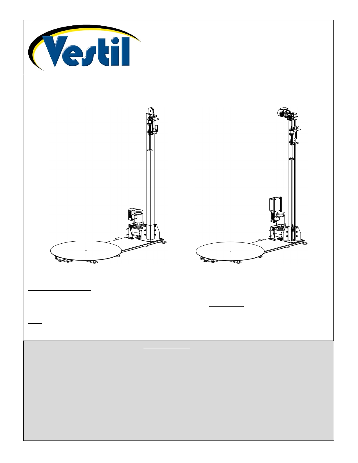
SWA-48 and SWA-48-PMO
Instruction Manual
SWA-48 SWA-48-PMO
Receiving instructions:
After delivery, remove the packaging from the product. Inspect the product closely to determine whether
it sustained damage during transport. If damage is discovered, immediately record a complete description
of the damage on the bill of lading. If the product is undamaged, discard the packaging.
Note:
The end-user is solely responsible for confirming that product design complies with all laws, regulations,
codes, and mandatory standards applied where the product is used.
Table of Contents
Signal Words……………….……………………………………...…….…………………………………………..…..…..2
Hazards of Improper Use…………………….………………………………………………………………..……….......2
Introduction…………………….…………….…………………………………………………………...…………………. 3
Installation………………………….………..………………………………………………..……………………...…….…3
Stretch Wrap Holder Assembly…………………………………..………………………………………………..……… 4
Belt Tensioning Procedure…………………………………………………………..………………………………..…... 5
Operation……………………………………………………………………………..……………………………..………. 5 - 7
Exploded Parts Views & Bills of Materials………………………………………………………………………..….…... 8 - 10
Labeling Diagram………..……………………………………………………………………………………………..….…11
Inspections & Maintenance………………………………………………………………………………………….....…..12
Troubleshooting……………………………………………………………………………………………...……..….…….13
Electrical Circuit Diagrams………………………………………………………………………………………………….14 - 15
Limited warranty……………………………………………………………………………………..………...………….... 16
Copyright 2017 Vestil Manufacturing Corp.; All rights reserved
Page 1 of 16
Page 2

4/12/2017
SWA-48, MANUAL
Signal Words
This manual uses SIGNAL WORDS to draw the reader’s attention to safety-related information. Signal words
indicate the likelihood of personal injuries as well as the probable seriousness of those injuries, if the product is
misused in the ways described. Other signal words call attention to uses of the product likely cause property damage.
Signal words used in this manual appear below along with the meaning of each word:
Identifies a hazardous situation which, if not avoided, WILL result in DEATH or SERIOUS
INJURY. Use of this signal word is limited to the most extreme situations.
Identifies a hazardous situation which, if not avoided, COULD result in DEATH or SERIOUS
INJURY.
Indicates a hazardous situation which, if not avoided, COULD result in MINOR or MODERATE
injury.
Identifies practices likely to result in product/property damage, such as operation that might
damage the product.
Hazards of Improper Use
Vestil diligently strives to identify foreseeable hazards associated with the use of its products. However, material
handling is inherently dangerous and no manual can address every conceivable risk. The end-user ultimately is
responsible for exercising sound judgment at all times.
If this product is used improperly or carelessly, personal injuries might result.
DO NOT modify the product in any way UNLESS you first obtain written approval from Vestil. Unauthorized
modifications automatically void the Limited Warranty and might make the product unsafe to use.
Read the manual whenever necessary to refresh your understanding of proper use and maintenance procedures.
DO NOT exceed the capacity of the unit (see Label 287 in “Labeling diagram” on p. 17).
DO NOT stand, or sit, on the turntable or the load at any time.
Install the machine ONLY on even, level surfaces where it will not be exposed to the outdoor environment.
Keep hands, clothing, etc. out of contact with all moving parts of the machine during operation.
During operation, stand with the mast between yourself and the turntable.
DO NOT activate the turntable UNLESS the load is centered on it and stable. Be prepared to stop the turntable,
because rotation can cause the load become unstable. An unstable load might topple during the wrapping process.
EVERY person in the area should remain far enough away from the machine to avoid contact with the load if it falls.
Higher rotation speed might cause an unstable load to slide off of the turntable.
DO NOT continue to use the machine if you observe abnor
mal motion or noise. Immediately tag the unit “Out of
service” and report the problem to maintenance personnel.
If you notice a malfunction during operation, DO NOT attempt to resolve it unless you are both authorized to do so
and certain that it will be safe to use afterwards. The unit must be in normal operating condition whenever it is used.
(See “Inspections & Maintenance” on p. 13).
Inspect the product before each use as directed on page 13. DO NOT use the machine unless it is in normal
operating condition.
DO NOT use this machine UNLESS all labels are in
on p. 12).
place, readable, and undamaged. (See “Labeling Diagrams”
Proper use, maintenance, and storage are essential for this product to function properly.
Always use this product in accordance with the instructions in this manual and consistent with any training
o
relevant to machines, devices, etc. used in conjunction with this product.
o
Periodically lubricate the chain.
o Keep the product clean & dry.
o Vestil uses only quality parts to make the equipment we manufacture. Vestil bears no responsibility for problems
that result as a consequence of using unapproved replacement parts. To order replacement or spare parts for this
equipment, contact the factory.
Copyright 2017 Vestil Manufacturing Corp.; All rights reserved
Page 2 of 16
Page 3

4/12/2017
SWA-48, MANUAL
Introduction
Vestil's Medium Duty Powered Stretch Wrap Machines offer the same great features as our standard duty machines
in a 5,000-lb capacity unit. Complete with a powered turntable and counter-balanced stretch film mast. To operate,
depress the foot pedal and manually move the mast up and down. The film-wrap tension is controlled with an
adjustable, friction-brake assembly. Film placement is controlled manually by moving the carriage assembly up and
down on the vertical mast. A hand operated carriage-brake allows the carriage to move freely making film application
fast and simple. The system will accept 10” to 20” material. The unit ships with the mast disconnected, simply raise
the mast and clamp into place. The standard manual film wrap delivery can be upgraded to 120 volt; 1-phase AC
powered mast option, PMO. The hand held control is used to raise/lower the film while the foot control is used to
operate the turntable. Please contact factory for Approach Ramp options on these models.
Installation
Review this entire instruction set before installing the stretch-wrap machine. Consult the manufacturer in the event
there are any questions or problems at the time of installation, or for information regarding optional features not
covered by the owner’s manual. The model SWA-48 stretch-wrap machine must be removed from the shipping wood
and securely anchored to the floor before use!
• Modifications or the addition of ancillary equipment to any part of the stretch-wrap machine without prior
manufacturer’s authorization may void the machine’s warranty.
• The installation should be made so that it complies with all regulations applicable to the machine and its location.
The end-user must verify that the supplied equipment is installed so it will be suited to the environment in which it
will be used.
• Installation must be performed by suitably trained personnel with access to the appropriate equipment. The
electrical aspects of the installation should be performed by an electrician.
• Choose a location for the machine that will be free of obstructions to the largest diameter load that could be placed
on the turntable. Consideration should also be given to the approach path(s) of pallet trucks and fork trucks so that
personnel, the motor speed control, and the foot switch and its cord can be adequately protected from injury or
damage.
For a typical installation, you will need the following:
1. A fork truck or hoisting means to unload the machine from the freight truck and to set it into place.
2. A smooth, level, and adequately strong concrete surface on which to mount the machine’s frame.
3. Concrete anchors, a masonry drill, a masonry bit, hand tools, grout, and steel shims. Consult the building’s
architect or facility engineer to determine the best size and type of hardware with which to anchor the machine
to the floor.
4. A power supply circuit and disconnect matching the motor voltage and current requirements. Refer to the
machine’s data plate, to the labels on the control enclosure, and to the electrical section in this manual, for more
information. The end-user is responsible for supplying the branch circuit’s required (by code) overcurrent and
short circuit protection.
Note: Static electricity is produced on the stretch-wrap film as it pulls off the roll during the stretch-wrapping of a
palletized load. The static effect might intensify in dry air. If undesirable effects of static on personnel or product are
experienced, consult an ESD (electrostatic discharge) product supplier for available methods to dissipate static.
Copyright 2017 Vestil Manufacturing Corp.; All rights reserved Page 3 of 16
Page 4
4/12/2017
Machine Installation:
SWA-48, MANUAL
1. Move the machine to its installation location by inserting the forks of a fork lift along each side of the frame until the
fork’s tips are under the ½” x 3” x 3” tabs on each side. Use care to avoid damaging the electrical components and
cable.
2. Prop up the motor end of the frame on a wooden 4 x 4 (or similar).
3. Stand the stretch-wrap mast upright on the end of the machine’s frame so that the material carriage arm projects
over the side of the frame. Align the hole in each corner of the mast mounting plate with its corresponding hole in
the machine’s frame.
4. Bolt the stretch-wrap mast to the machine’s frame with the hardware provided, and wrench-tighten.
5. Remove the counterbalance retaining screw located approximately 12” up from the mast’s base plate, and cut the
cable tie holding the mast cable to the pulley at the top of the mast.
6. Anchor the machine’s frame to the floor through the 9/16” holes located at the frame corners and at the end of the
frame, under the edge of the turntable. Tighten the anchors only to the point where the frame is level.
7. Shim and/or grout under the frame sides as necessary to prevent bowing of the frame.
8. Tighten all of the floor anchors wrench-tight.
9. Bolt the motor/drive assembly onto the gear reducer using the included hardware and shaft key. When finished,
the electronic drive should be facing outward over the side of the machine’s frame.
10. Insert the turntable’s power cord plug into a standard 15A or 20A, 120 VAC receptacles. If a powered mast is
installed onto the machine, the turntable’s power cord can plug into the pigtail coming out of the mast’s control
enclosure, and the mast’s power cord can then be plugged into a 120V receptacle to supply both parts of the
machine.
11. Verify that the turntable rotates and that the speed control knob provides full speed range adjustment.
12. If a powered mast is installed, verify that the mast operates and that the mast's upper and lower travel limit
switches function properly.
13. Clean up debris, and verify that all labels are intact (see “Labeling diagram” on p. 10).
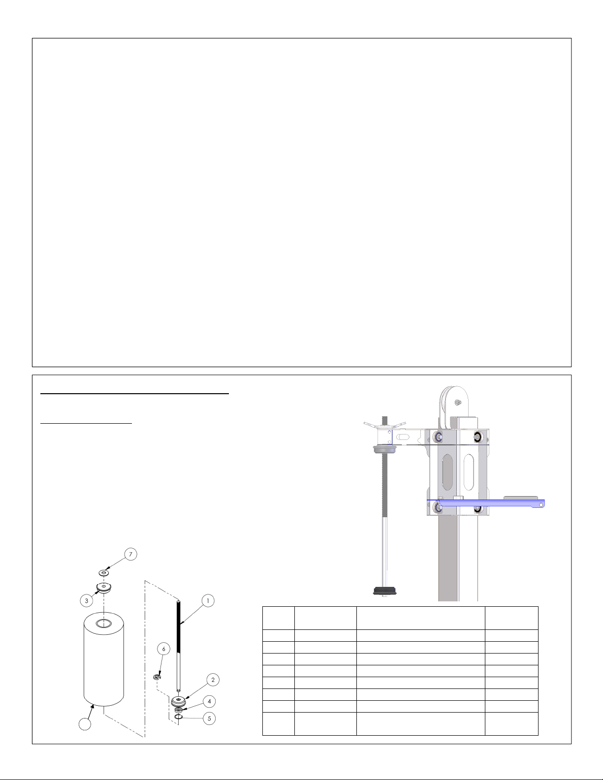
Stretch Wrap Holder Assembly
The wrap holder accommodates 10-20 inch rolls of stretch wrap.
Loading stretch wrap:
1. Unwind the wing nut (A) sufficiently to remove the lock spacer (6)
underneath the bottom retainer (2).
2. Remove the lock spacer.
3. Remove the retainer (5) and bearing (4).
4. Remove the spent roll of stretch wrap and install a new roll.
5. Reinstall the retainer (5); secure it in place with the lock spacer (6).
6. Tighten the wing nut (A) until the roll is snugly grasped between the
tube retainers (2) and (3). Adjust the tightness of the wing nut to
achieve the desired degree of material stretch—the material will
stretch more the more tightly the roll is grasped.
Item
no.
Part no. Description Quantity
1 20-014-116 Frame, rod, wrap retainer 1
2 20-014-006 Tube retainer (bottom) 1
3 20-014-005 Tube retainer (top) 1
4 20-110-002 Bearing, ball, 3/4 in., shield 1
5 68061 15/8 in. retainer ring 1
6 20-113-022 Spacer, lock 1
7 20-113-003 7/8 in. fiber washer 1
8
Copyright 2017 Vestil Manufacturing Corp.; All rights reserved Page 4 of 16
*8 SRF-18
20in. plastic wrap (not
included)
1
Page 5
1
2 2
2
4 5
5
4/12/2017
SWA-48, MANUAL
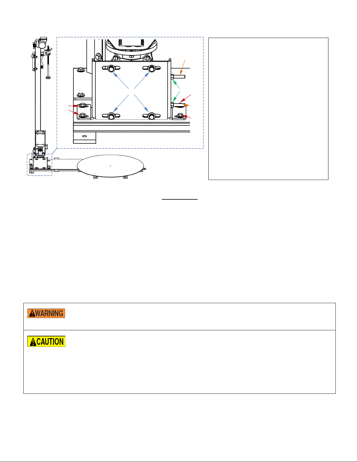
Belt Tensioning Procedure:
Numbers in the diagram to the left
correspond to the procedure numbers
below.
1. Loosen all 4 bolts which hold the gear
reducer to its mounting bracket.
2. Loosen the mounting bolts and slide the
bracket to the left.
3. Retighten the bolts loosened in step 1.
4. Loosen the jam nuts.
5. Turn the screws clockwise to increase
belt tension (CCW to reduce tension).
Operation
6. Retighten the jams nuts (4) and
mounting bolts (2).
Ensure that all employees involved in the operation and care of this machine understand and follow these
instructions.
The standard model SWA-48 is suitable for moderate-duty, intermittent cycling with a 4,000 pound load. It is intended to
be used indoors in industrial and commercial locations to apply stretch-wrap material at between three and twelve
revolutions per minute (RPM) in a clockwise rotation around palletized, stable, non-hazardous loads. The maximum
diameter (or diagonal, measured corner-to-corner) load size for the SWA-48 is 76”, the maximum load height is 78”.
Always ensure that the load is centered on the turntable.
The material mast can utilize stretch-wrap material rolls in lengths from 10” to 20” — spacer tubes stored on the material
rod allow for the use of several material roll lengths below 20”. The SWA will generally be capable of achieving stretchwrap material stretch rates of 150-200%.
Loading:
Verify that no part of the load is overhanging below the turntable. A damaged skid with a
dragging board or an overhanging load that sags below the turntable can cause the entire load to
shift suddenly if it catches on the frame.
Do not exceed the machine’s load ratings. Damage or premature failure to the drive system or its
components could result from exceeding the listed capacity. Place loads onto the turntable
slowly and gently using a pallet truck or walk-behind fork lift, using an optional approach ramp, or
with a fork truck.
Do not drop loads onto the turntable. Even a two-inch drop onto the turntable creates a shock
load on the load bearings that will result in their premature failure.
See the installation page in this manual for instructions on how to install a roll of stretch-wrap
material onto the mast carriage.
The load rating, in pounds, is shown on the machine data plate located on the frame near the gear reducer mounting
bracket. It indicates the net capacity of the turntable with a load that is centered and evenly distributed.
Note: The addition of any ancillary equipment to the turntable, such as a conveyor, must be taken into account when
determining the maximum working load to be placed on the turntable.
Copyright 2017 Vestil Manufacturing Corp.; All rights reserved Page 5 of 16
Page 6

4/12/2017
SWA-48, MANUAL
Operation:
Keep all personnel clear of the machine when it is in operation. Be certain no part of any person,
fork truck, or other object is in the path of the rotating load before rotating the turntable.
Do not stand or sit on the turntable or its load at any time.
Keep all body parts and clothing away from the machine’s drive system(s).
Do not use the stretch-wrap machine if any damage or unusual noise is observed, if it is in need
of repairs, or if it seems to be malfunctioning. Notify your supervisor or maintenance personnel if
you notice anything out of the ordinary.
The standard stretch-wrap machine is furnished with a constant-pressure (dead-man style) foot switch control. Pressing
the foot switch will turn on the motor to rotate the turntable. The turntable will rotate only while the control is pressed.
Upon releasing the control, the turntable will coast to a stop.
The turntable speed can be adjusted with the speed control knob on the front of the motor speed control. The display on
the front of the motor controller shows the approximate RPM of the turntable. Turn the speed control knob clockwise to
increase the turntable speed, and counterclockwise to decrease the speed.
Pull the handle upward to move the stretch-wrap material roll upward. Push the handle down to move the material
downward. Control of the tension/stretch of the stretch-wrap material is achieved by turning the handle on top of the
material.
Screw the handle clockwise, downward, to increase the material tension and stretch, and turn it counterclockwise, upward,
to decrease the material stretch.
Always carefully watch the palletized load when the turntable is rotating.
Set the material tensioner so the material will pull off the roll easily. Pull stretch-wrap material off the roll and either hold or
tie it to the load to be wrapped. Press the foot switch to rotate the load.
After one or two overlaps, tension the material to the desired stretch rate. Raise and lower the material carriage until the
load is covered 100%, with two or three overlaps. While the turntable is still rotating, the material can either be cut with a
knife or torn with the hands. Press and smooth the cut end of the material up against the side of the load.
Note: The best wrapping results for palletized loads is generally achieved by having the wrap overlap the sides of the pallet
at the bottom and extending slightly above the load at the top. Ensure that all safety and warning labels stay in place and
are legible. Refer to the labels page in this manual.
Changing Delta Motor Speed Controller Parameters:
Prog
1) Press to switch to the program mode.
Data
a) The following screen, , will appear.
0-
This indicates the specific parameter group.
b) Use the following keys, shown on the next page, to change all parameter settings in Step 2.
Copyright 2017 Vestil Manufacturing Corp.; All rights reserved Page 6 of 16
Page 7

4/12/2017
SWA-48, MANUAL
Press "PROG/DATA" key to select parameter group and to store entered data.
"END" displays for approx. 0.5 sec. if input has been accepted.
Press "MODE" to scroll through all status at the drive;
MODE
To show the turntable speed on the display, press "mode" three times after initial power-up. For
example, when the turntable is rotating at 12 rpm, the display will appear as "u 12."
Press "UP" or "DOWN" key to scroll through different parameters.
Press "UP" or "DOWN" key momentarily will change parameter settings in single-unit increments.
1. Drive Parameter Settings
Parameter Parameter Description Setting Setting Description
0-03 Start-Up Display Selection d 2
Display the content of user-defined unit.
Scales the frequency value so the display shows the
0-05 User Defined Coefficient K d 0.3
approximate turntable rpm.
1-02 Maximum Output Voltage d 255
1-07
1-08
Upper Bound of
Frequency
Lower Bound of
Frequency
d 65
d 15
Sets the maximum voltage to the motor
Sets the maximum rotation speed with the speed knob turned
fully clockwise (about 11 rpm).
Sets the minimum rotation speed with the speed knob turned
fully counterclockwise (about 3 rpm).
Time to accelerate the motor to the drive's maximum output
1-09 Acceleration Time 1 d 10
1-15
Auto Acceleration /
Deceleration
d 0
1-16 S-Curve in Acceleration d 7
2-00
2-01
Source of Frequency
Command
Source of Operation
Command
d 3
d 1
2-02 Stop Method d 1
6-02
6-03
Over-Current Stall
Prevention Level
Over-Torque Detection
Mode
d 150
d 3
frequency set point, in seconds.
Allows for a linear acceleration rate of the motor.
Determines how smoothly the drive accelerates.
Allows the turntable speed to be controlled by the knob of the
drive's keypad.
Makes the drive turn on the external foot switch.
Allows the turntable to coast to a stop.
Sets the maximum motor current, as a percentage of the
drive's rated output.
Detection is enabled during Acceleration and continues until
the Continuous Output Time Limit is reached.
Sets the maximum output torque, as a percentage of the
drive's rated output.
Determines the time the drive will run after over torque is
detected, in seconds.
6-04
6-05
Over-Torque Detection
Level
Continuous Output Time
Limit
d 200
d 10
Affects the point at which the drive limits its output current, in
7-00 Motor Rated Current d 120
7-01 Motor No-load Current d 75
7-02 Torque Compensation d 10
Copyright 2017 Vestil Manufacturing Corp.; All rights reserved Page 7 of 16
percent of drive's rated output.
Affects the drive's motor slip compensation.
Controls the motor's maximum start-up torque.
Page 8

3
3
5
4/12/2017
SWA-48, MANUAL
SWA-48 Exploded Parts Diagram and Bill of Materials
Item Part no. Description Qty. Item Part no. Description Qty.
1 20-514-006 Weldment, main frame 1
2 20-513-001 Weldment, turntable deck 1
3 20-542-006 Weldment, pulley/pin 1
4 20-110-001 Single row ball bearing, shielded 1
5 20-117-001 Internal retaining ring, 2” 1
6 20-117-003 External retaining ring, 1” dia. 1
7 11103
8 33008
Hex bolt, grade A, zinc plated,
16x
Flat washer, low carbon, USS, zinc
plated,
3
/4”
3
/8”
/8”-
9 20-110-003 Cam roller with seal 10
10 11061
Bolt, HHCS #2, zinc plated,
18x2”
/16”-
11 33004 Flat washer, USS, zinc plated, 1/4” 20
12 37021
Nylon insert lock nut, grade 2, zinc
5
finish,
/16”-18
13 20-042-020 Belt, B115 1
14 20-016-032 Bracket, motor mount, formed 1
15 20-641-006
16 13107
17 33622
18 20-514-084
4
19 20-001-153 Bracket, mast mount 1
16
20 36106
21 11105
10
22 25552
Subassembly, control
box/motor/reducer, 115VAC
Bolt,
/8”-16x11/4”, HHCS, #5,
zinc plated
Split lock washer, carbon steel,
medium zinc finish,
3
/8”
Subassembly, counter-balanced
mast, manual
Hex nut, grade a, zinc plated,
3
/8”-16
Hex bolt, grade A, zinc plated,
3
/8”-16x1”
Socket set screw, black oxide,
3
/8”-16x4”
23 20-016-033 Bracket, motor mount 2
10
1
8
12
1
10
4
2
Copyright 2017 Vestil Manufacturing Corp.; All rights reserved Page 8 of 16
Page 9

3
3
3
3
1
1
otor/reducer,
3
4/12/2017
SWA-48, MANUAL
Item Part no. Description Qty. Item
1 20-514-006 Weldment, main frame 1
2 20-513-001 Weldment, turntable deck 1
3 20-542-006 Weldment, pulley/pin 1
4 20-110-001 Single row ball bearing, shielded 1
5 20-117-001 Internal retaining ring, 2” 1
6 20-117-003 External retaining ring, 1” dia. 1
7 11103
8 33008
9 20-110-003 Cam roller with seal 10
10 11061 Bolt, HHCS #2, zinc plated, 5/16”-18x2” 10
11 33004 Flat washer, USS, zinc plated, 1/4” 20
12 37021
13 20-042-020 Belt, B115 1 29 11005
SWA-48-PMO Exploded Parts Diagram and Bill of Materials
Hex bolt, grade A, zinc plated,
3
16x
/4”
Flat washer, low carbon, USS, zinc
3
plated,
Nylon insert lock nut, grade 2, zinc
finish,
/8”
5
/16”-18
/8”-
17 33622
18 20-001-153 Bracket, mast mount 1
19 36106 Hex nut, grade a, zinc plated,
20 11105
21 25552
22 20-514-084
4
23 20-016-136 Bracket, junction box mount 1
16
24 20-016-135 Bracket, limit switch 1
25 01-029-007
26 01-022-001 Limit switch with roller arm 1
27 11001
10
28 37018
Part no. Description Qty.
Split lock washer, carbon steel,
medium zinc finish,
3
/8”
Hex bolt, grade A, zinc plated,
16x1”
Socket set screw, black oxide,
16x4”
Subassembly, counter-balanced
mast, manual
Junction box with lid, 6”x8”x4”, not
NEMA 4
Hex bolt, grade A, zinc plated,
1
20x
/2”
Nylon lock nut, grade 2, zinc finish,
1
/4”-20
Bolt,
/4”-20UNCx1”, HHCS #2, zinc
plated
/8”-16 10
/8”-
/8”-
/4”-
12
4
2
1
1
2
2
4
14 20-016-032 Bracket, motor mount, formed 1 30 33618 Medium split lock washer, 1/4” 4
15 20-641-006
16 13107 Bolt,
Subassembly, control box/m
115VAC
/8”-16x11/4”, HHCS, #5, zinc plated 8 32 31802 Screw, self-tapping 2
1 31 36102 Hex nut, grade A, zinc plated,
1
/4”-20 4
33 20-016-033
Copyright 2017 Vestil Manufacturing Corp.; All rights reserved Page 9 of 16
Page 10

4/12/2017
3
3
3
Stretch wrap carriage subassembly exploded parts diagram & bill of materials
Item Part no. Description Quantity
1 20-514-080 Weldment, carriage frame 1
2 20-145-010
3 21-113-021 Spacer, bearing shaft 8
4 20-110-006 Roller bearing 8
5 11109
6 11111
7 20-040-001 Lever, brake release, formed 1
8 21-113-020 Spacer, bearing 4
9 20-113-023 Spacer 1
10 20-146-008 Spring, compression spring 1
11 99-112-006 Pin, clevis 1
12 33008 3/8in. USS zinc-plated flat washer 10
13 37024 3/8in. Nylock insert nut 9
14 64076 1/8in. x 1in. zinc-plated cotter pin 1
15 20-537-018 Brake pad assembly 1
16 11105
17 33622 3/8in. zinc-plated lock washer 1
18 65078 1/8in. x 11/2in. zinc-plated cotter pin
Specialty hardware, clamp, wrap,
mounting
/8in. – 16 x 11/2in. HHCS #2
zinc—plated bolt
/8in. – 16 x 2in. HHCS #2 zinc—
plated bolt
/8in. – 16 x 1in. HHCS #2 zinc-
plated bolt
SWA-48, MANUAL
1
4
4
1
1
Manual counterbalanced mast subassembly exploded parts diagram & bill of materials
Item Part no. Description Quantity
1 20-538-005 Subassembly, carriage 1
2 20-514-082 Subassembly, mast, manual 1
3 26333 Shoulder screw 0.375in. x 1.5in. 1
4 33008 3/8in. USS zinc-plated flat washer 2
5 37024 3/8in. Nylock insert nut 1
6 20-027-001 Pulley, counterweight 1
7 20-145-019 Specialty hardware, swage sleeve
8 20-145-018 Specialty hardware, cable 1
9 28-014-179 Cast, counterweight (SWA-48) 1
10 20-620-001
11 20-113-003 7/8in. fiber washer 2
12 20-014-005 Frame, tube retainer, (top) 1
13 68061 15/8in. retainer ring 1
14 20-014-006 Tube, retainer, (bottom) 1
15 20-111-002 Bearing, 7R16 1
16 20-014-116 Frame, rod, wrap retainer 1
17 20-113-022 Spacer, lock 1
Weldment, specialty hardware,
rod tension wing nut
2
1
Copyright 2017 Vestil Manufacturing Corp.; All rights reserved
Page 10 of 16
Page 11

4/12/2017
Labeling Diagrams:
SWA-48, MANUAL
A: Label 248
A
D
E
B
SWA-48
C
B: Label 221
A
D
E
SWA-48-PMO
B
C
C: Label 204
D: Label 287
Copyright 2017 Vestil Manufacturing Corp.; All rights reserved
E: Label 220
Page 11 of 16
Page 12

4/12/2017
SWA-48, MANUAL
Inspections & Maintenance
Before using the machine for the first time, make a written record of its appearance. Include observations about
each part. Raise and lower the shrink wrap carriage. Include notes about how rapidly the carriage moves up and
down the mast as well as sounds made during operation. Turn on the turntable. Record your observations about as
well as sounds heard during operation.
This record establishes “normal condition”. During future inspections, compare current observations to the written
record to determine if the unit is in normal condition. DO NOT use the crane unless it is in normal condition. If repairs
are necessary, only install manufacturer-approved replacement parts.
Note: Record the maximum turntable rotation speed when the machine is installed. This will allow a reference for
evaluating drive belt slippage during future maintenance checks.
Initial Inspection: before using the new product for the first time, inspect it to confirm normal operating condition.
Before each use inspect:
1. Frayed or damaged wires.
2. Damage or structural deformation to the stretch-wrap mast, the machine’s frame, or the turntable.
3. Damage to any of the machine’s control or power transmission components, particularly to the foot switch, its
guard, or its cord.
4. Unusual noise or binding, or evidence thereof.
5. Smooth and proper movement of the stretch-wrap mast carriage.
Monthly Inspections:
1. Worn or damaged electrical wires.
2. Damage to the motor speed control. If the speed control’s enclosure has been broken, the drive should be
replaced.
3. Looseness of the drive belt. See “Note,” above. Slipping of the drive belt will cause it to wear out rapidly, and
the turntable will rotate slower than intended or not at all. The belt tension is adjusted by the socket-head screws on
the side of the gear reducer mounting bracket. See the “Belt Tensioning Procedure” on page 5.
4. Wear or impact damage to the edge of the turntable plate.
Sharp edges or burrs can develop at the edge of the turntable plate by a fork truck’s forks scraping
the top of the plate or by a fork impacting the edge of the plate during loading and unloading. To
prevent potential injury to personnel, these must be filed, sanded or ground smooth.
5. Damaged or worn load bearings. This is indicated by a scraping sound from the turntable during operation and
by grooves developing on the bottom side of the turntable.
6. Wear of the turntable’s main bearing. Check that the turntable is parallel with the top of the machine’s frame
and that there is no wobble when the edge of the turntable is shaken.
7. Excessive wear to the mast carriage slides, or to the fiber washer under the stretch-wrap material.
8. The integrity of the frame anchors, and for cracks in the concrete around them.
9. Unusual noises or movement during operation.
10. All the information, safety, and warning labels being in place and in good condition.
11. Clean off dirt and debris, particularly built up underneath the turntable. In the event of a sudden and severe
shock load to the turntable’s drive system; such as when the spinning load is instantly stopped due to a fork
truck backing into the load, damage may occur to the drive system components (belt, pulleys, torque limiter,
gear reducer, motor). Such damage is not covered under warranty. The gear reducer uses. Disassembly of
the gear reducer will void the warranty, and at the manufacturer’s discretion may void all warranty of the stretchwrap machine.
Copyright 2017 Vestil Manufacturing Corp.; All rights reserved
Page 12 of 16
Page 13

4/12/2017
Troubleshooting
Problem Cause Action
• The turntable does not
rotate.
Or
• The turntable will not
rotate without assistance,
rotates slower when
loaded, or will not achieve
maximum speed.
The powered mast motor or
control enclosure hums,
chatters, or buzzes, and the
film carriage does not
move, or it moves only
slowly.
Powered mast must
carriage will raise but it will
not lower.
No power supply voltage.
• Speed control at its slowest setting
• No control signal from the foot
switch.
• Motor controller fault, or defective
motor controller.
• Broken or slipping belt.
• Excess voltage drop to the motor
due to: power wire size too small,
wire run to long, or incoming
voltage too low.
• Damage to the mast or carriage.
• Low control voltage or bad
connection in control circuit.
• See as last item above.
• Transformer fuse is blown.
• No power supply voltage.
• Mast limit switch is engaged or bad.
• Control relay 1 CR, left side in the
enclosure, contact is burnt.
• Control relay 1 CR has become
loose.
• Control relay 2 CR has become
loose.
• Control relay 2 CR is defective.
• Bad connection in control circuit.
• Physical blockage of the structure.
SWA-48, MANUAL
Check for 120V at the outlet into which the
machine is connected. Find cause of power
supply loss before resupplying power.
If the turntable cord is plugged into the pigtail at
the powered mast's enclosure, verify that the
powered mast cord is plugged into an outlet.
• Increase the turntable speed at the knob on the
front of the motor controller.
• Check the foot switch and its cable for continuity.
• Check the display on the controller for a fault
code. Contact the factory.
• If the fan on the drive motor is spinning, lift the
mast end of the machine to inspect the belt.
• Check power supply for adequacy.
• Check incoming voltage while the motor is
running. Correct by installing a circuit with larger
wire, eliminating extension cords, or installing a
buck/boost transformer.
• Visually inspect the carriage and mast for signs
of damage or excessive wear.
• Verify 24 VAC at transformer secondary. Inspect
all wires and connections in the mast control
enclosure for looseness, etc.
• See last paragraph above.
• Test with meter; replace if bad. Replace with the
same fuse type and ampere value.
• See first item at the top of the page.
• Inspect and test switch. Replace if bad.
• Inspect contact. Clean contact or replace relay if
burnt. Check for 120V at the motor relay.
• Verify that the relay is firmly in place.
• See last paragraph above.
• Inspect and test control relay 2 CR. Replace if
bad.
• Test all parts of circuit with meter.
• Inspect for foreign material or objects that might
block the carriage path.
Copyright 2017 Vestil Manufacturing Corp.; All rights reserved Page 13 of 16
Page 14

4/12/2017
SWA-48, MANUAL
SWA-48 Electrical Circuit Diagrams (20-124-012 Rev. G)
Disconnect the unit from electrical power before beginning work on the electrical system. Only
qualified, trained individuals should attempt troubleshooting and repair of this equipment.
Copyright 2017 Vestil Manufacturing Corp.; All rights reserved
Page 14 of 16
Page 15

4/12/2017
SWA-48, MANUAL
SWA-48-PMO Electrical Circuit Diagrams (20-124-015 Rev. J)
Disconnect the unit from electrical power before beginning work on the electrical system. Only
qualified, trained individuals should attempt troubleshooting and repair of this equipment.
Copyright 2017 Vestil Manufacturing Corp.; All rights reserved
Page 15 of 16
Page 16

4/12/2017
LIMITED WARRANTY
SWA-48, MANUAL
Vestil Manufacturing Corporation (“Vestil”) warrants this product to be free of defects in material and workmanship
during the warranty period. Our warranty obligation is to provide a replacement for a defective original part if the part is
covered by the warranty, after we receive a proper request from the warrantee (you) for warranty service.
Who may request service?
Only a warrantee may request service. You are a warrantee if you purchased the product from Vestil or from an
authorized distributor AND Vestil has been fully paid.
What is an “original part”?
An original part is a part used to make the product as shipped to the warrantee.
What is a “proper request”?
A request for warranty service is proper if Vestil receives: 1) a photocopy of the Customer Invoice that displays the
shipping date; AND 2) a written request for warranty service including your name and phone number. Send requests by
any of the following methods:
Mail
Fax Email
Vestil Manufacturing Corporation (260) 665-1339 sales@vestil.com
2999 North Wayne Street, PO Box 507
Phone
Angola, IN 46703 (260) 665-7586
In the written request, list the parts believed to be defective and include the address where replacements should be
delivered.
What is covered under the warranty?
After Vestil receives your request for warranty service, an authorized representative will contact you to determine
whether your claim is covered by the warranty. Before providing warranty service, Vestil may require you to send the
entire product, or just the defective part or parts, to its facility in Angola, IN. The warranty covers defects in the following
original dynamic components: motors, hydraulic pumps, electronic controllers, switches and cylinders. It also covers
defects in original parts that wear under normal usage conditions (“wearing parts”): bearings, hoses, wheels, seals,
brushes, batteries, and the battery charger.
How long is the warranty period?
The warranty period for original dynamic components is 1 year. For wearing parts, the warranty period is 90 days. The
warranty periods begin on the date when Vestil ships the product to the warrantee. If the product was purchased from
an authorized distributor, the periods begin when the distributor ships the product. Vestil may, at its sole discretion,
extend the warranty periods for products shipped from authorized distributors by up to 30 days to account for shipping
time.
If a defective part is covered by the warranty, what will Vestil do to correct the problem?
Vestil will provide an appropriate replacement for any covered part. An authorized representative of Vestil will contact
you to discuss your claim.
What is not covered by the warranty?
1. Labor;
2. Freight;
3. Occurrence of any of the following, which automatically voids the warranty:
Product misuse;
Negligent operation or repair;
Corrosion or use in corrosive environments;
Inadequate or improper maintenance;
Damage sustained during shipping;
Collisions or other incidental contacts causing damage to the product;
Unauthorized modifications: DO NOT modify the product IN ANY WAY without first receiving written
authorization from Vestil. Modification(s) might make the product unsafe to use or might cause excessive and/or
abnormal wear.
Do any other warranties apply to the product?
Vestil Manufacturing Corp. makes no other express warranties. All implied warranties are disclaimed to the extent
allowed by law. Any implied warranty not disclaimed is limited in scope to the terms of this Limited Warranty.
Copyright 2017 Vestil Manufacturing Corp.; All rights reserved
Page 16 of 16
 Loading...