

Page 1
rev. 11/4/2013 MDU-C, Manual
VESTIL MANUFACTURING CORP.
2999 North Wayne Street, P.O. Box 507, Angola, IN 46703
Telephone: (260) 665-7586 -or- Toll Free (800) 348-0868
Fax: (260) 665-1339
www.vestilmfg.com e-mail: sales@vestil.com
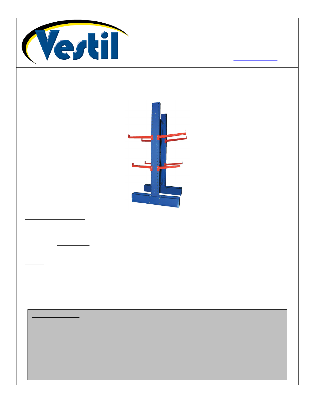
MDU-C-SERIES STORAGE RACKS
INSTRUCTION MANUAL
Receiving instructions:
After delivery, IMMEDIATELY remove the packaging from the product in a manner that preserves the
packaging and maintains the orientation of the product in the packaging; then inspect the product closely
to determine whether it sustained damage during transport. If damage is discovered during the
inspection, immediately record a complete description of the damage on the bill of lading. If the
product is undamaged, discard the packaging.
NOTES:
1) Compliance with laws, regulations, codes, and non-voluntary standards enforced in the location where
the product is used is exclusively the responsibility of the owner/end-user.
2) VESTIL is not liable for any injury or property damage that occurs as a consequence of failing to apply either:
a) Instructions in this manual; or b) information provided on labels affixed to the product.
Neither is Vestil
responsible for any consequential damages sustained as a result of failing to exercise sound judgment
while assembling, installing, using or maintaining this product.
Table of Contents
Hazard identification: explanation of signal words…………………………………………………………………… 2
Safety Guidelines……………………………………………………………………………………………………….. 2
Product Specifications by Model…………………... ………………………………………………………………… 3
FIG. 1A: MDU-C exploded parts diagram…………………………………………………………………………….. 4
FIG. 1B: Upright posts…………………………………………………………………………………………………. 4
MDU-C-6 & MDU-C-8 bills of materials……………………………………………………………………………… 5
MDU-C-10 bill of materials……………………………………………………………………………………………. 6
Assembly instructions………………………………………………………………………………………………. 6-8
Maintenance………………………………………………………………………………........................................... 8
Limited warranty…………………………………………………………………………………………………………. 9
Copyright 2013 Vestil Manufacturing Corp. Page 1 of 9
Page 2
rev. 11/4/2013 MDU-C, Manual
Hazard Identification--Explanation of SIGNAL WORDS
This manual uses SIGNAL WORDS to indicate the likelihood of personal injuries, as well as the probable
seriousness of those injuries, if the product is misused in the ways described. Other signal words call attention to
uses of the product likely cause property damage.
The signal words used appear below along with the meaning of each word:
Identifies a hazardous situation which, if not avoided, WILL result in DEATH or
SERIOUS INJURY. Use of this signal word is limited to the most extreme
Identifies a hazardous situation which, if not avoided, COULD result in DEATH or
Indicates a hazardous situation which, if not avoided, COULD result in MINOR or
Identifies practices likely to result in product/property damage, such as operation that
Each person who assembles, installs, uses, or maintains this product should read the entire manual in advance
and fully understand the directions. If after reading the manual you do not understand an instruction, ask
your supervisor or employer for clarification, because failure to adhere to the directions in this manual
might result in serious personal injury.
SAFETY GUIDELINES
Vestil diligently strives to identify foreseeable hazards associated with the use of its products. However, material
handling is inherently dangerous and no manual can address every conceivable risk. The end-user ultimately is
responsible for exercising sound judgment at all times.
situations.
SERIOUS INJURY.
MODERATE injury.
might damage the product.
Electrocution might result if any part of the rack system or items or materials placed on the rack contacts
electrified wires. Reduce the likelihood of electrocution by applying common sense:
DO NOT install the rack in a location where contact with electrified wires will occur.
If this product is used or assembled improperly or carelessly, people in the area might sustain serious
personal injuries or even be killed. ALWAYS use the product properly:
Failure to read and understand the entire manual before assembling, installing, loading or servicing the
product constitutes misuse. Read the manual to refresh your understanding of proper use and maintenance
procedures as necessary.
DO NOT exceed the maximum rated load.
Inspect the rack periodically (AT LEAST once per month). DO NOT continue to use the rack if the inspection reveals
structural damage. Examples of structural damage include: 1) warped, deformed, or damaged posts (uprights) or
beams; 2) cracked welds; 3) enlargement of openings that receive beam studs; 4) corrosion, severe wear, or other
condition that affects the ability of the product to support applied weight; 6) damaged, deformed or cracked crosssupports. Immediately tag out the rack, unload it completely, and replace each part that fails to pass an inspection. DO
NOT use the product until it is fully restored to normal condition. ONLY use manufacturer-approved replacement parts.
DO NOT use the product if any unusual noise or movement is observed. If a malfunction occurs, remove the unit from
service and notify your supervisor or maintenance personnel about the issue.
All loads stored on the rack must fit within the dimensions of the rack. DO NOT store any load that hangs over the
rack.
DO NOT use the pallet rack UNLESS it is securely anchored to the ground.
ALWAYS evenly distribute and center the load on the rack.
ONLY use this rack on even, level surfaces.
DO NOT remove or obscure any label. All product labels must be readable and undamaged.
DO NOT climb or sit on the rack.
DO NOT modify the rack in any way. Unauthorized modifications automatically void the limited warranty (see p.
6) and might make the rack unsafe to use.
Proper maintenance is essential for this product to function properly and to last as long as possible.
o Always use this product in accordance with the instructions in this manual and consistent with any training relevant
to the storage of materials on racks.
o Keep the rack clean & dry.
Copyright 2013 Vestil Manufacturing Corp. Page 2 of 9
Page 3

rev. 11/4/2013 MDU-C, Manual
Product Specifications by Model:
Base
Model Height
MDU-C-6-12 6ft. 34in. 16,200 lb. (~7,363.6kg) MSA-C-12 or MIA-C-12
MDU-C-6-18 6ft. 46in. 13,200 lb. (~6,000kg) MSA-C-18 or MIA-C-18
MDU-C-6-24 6ft. 58in. 11,000 lb. (~5,000kg) MSA-C-24 or MIA-C-24
MDU-C-6-36 6ft. 82in.
MDU-C-8-12 8ft. 34in. 15,200 lb. (~6,909.1kg) MSA-C-12 or MIA-C-12
MDU-C-8-18 8ft. 46in. 12,600 lb. (~5,727.3kg) MSA-C-18 or MIA-C-18
MDU-C-8-24 8ft. 58in. 10,600 lb. (~4,818.2kg) MSA-C-24 or MIA-C-24
MDU-C-8-36 8ft. 82in.
MDU-C-10-12 10ft. 34in. 14,200 lb. (~6,454.5kg) MSA-C-12 or MIA-C-12
MDU-C-10-18 10ft. 46in. 11,800 lb. (~5,363.6kg) MSA-C-18 or MIA-C-18
MDU-C-10-24 10ft. 58in. 10,000 lb. (~4,545.5kg) MSA-C-24 or MIA-C-24
MDU-C-10-36 10ft. 82in.
Straight arms
support
length
Capacity Arm model Net Weight
9,400 lb. (~4,272.7kg)
OR
8,200 lb. (~3,727.3kg)
9,000 lb. (~4,090.9kg)
OR
8,000 lb. (~3,636.4kg)
8,800 lb. (~4,000kg)
OR
7,600 lb. (~3,454.5kg)
MSA-C-30; MIA-C-30
OR
MSA-C-36; MIA-C-36
MSA-C-30; MIA-C-30
OR
MSA-C-36; MIA-C-36
MSA-C-30; MIA-C-30
OR
MSA-C-36; MIA-C-36
145 lb.
(65.9kg)
155 lb.
(70.5kg)
165 lb.
(75kg)
190 lb.
(86.4kg)
165 lb.
(75kg)
175 lb.
(79.5kg)
185 lb.
(84.1kg)
210 lb.
(95.5kg)
185lb.
(84.1kg)
195lb.
(88.6kg)
205lb.
(93.2kg)
230lb.
(104.5kg)
Model Arm length Capacity Net weight
MSA-C-12
MSA-C-18
MSA-C-24
MSA-C-30
MSA-C-36
Inclined arms
Model Arm length Capacity Net weight
MIA-C-12
MIA-C-18
MIA-C-24
MIA-C-30
MIA-C-36
12in.
30.5cm
18in.
45.7cm
24in.
~61cm
30in.
76.2cm
36in.
91.4cm
12in.
30.5cm
18in.
45.7cm
24in.
~61cm
30in.
76.2cm
36in.
91.4cm
1,000 lb.
454.5kg
750 lb.
340.9kg
600 lb.
272.7kg
500 lb.
227.3kg
400 lb.
181.8kg
1,000 lb.
454.5kg
750 lb.
340.9kg
600 lb.
272.7kg
500 lb.
227.3kg
400 lb.
181.8kg
11 lb.
5kg
13 lb.
5.9kg
15 lb.
6.8kg
17 lb.
7.7kg
19 lb.
8.6kg
11 lb.
5kg
13 lb.
5.9kg
15 lb.
6.8kg
17 lb.
7.7kg
19 lb.
8.6kg
Copyright 2013 Vestil Manufacturing Corp. Page 3 of 9
Page 4

rev. 11/4/2013 MDU-C, Manual
FIG. 1A: MDU-C exploded parts diagram (bills of materials appear on p. 3 & 4)
FIG. 1B: Upright posts
Bolt
holes for
back
braces
Bolt
plate
Holes for
M20-2.5
x 40mm
bolts
Upright post
Copyright 2013 Vestil Manufacturing Corp. Page 4 of 9
Page 5

rev. 11/4/2013 MDU-C, Manual
MDU-C-6 bill of materials
NOTE: You will receive straight and/or inclined arms as per your order.
Item no. Part no. Description Quantity
1 MDU-1-UR-6 Double-sided upright post, 6ft. model 2
2 MDU-1-DB-6 Double-sided base frame, 6ft. model 2
3 MDU-3-BB Back brace 2
4 MDU-4-CB Cross bar 2
5 MSA-C-6 Straight arm, medium duty, 6ft. model as ordered
6 MIA-C-6 Inclined arm, medium duty, 6ft. model as ordered
7 MDU-7-LB Locking bar 1 per arm
8 MDU-8-PIN Pin 2 per arm
9 MDU-9-BOLT M20-2.5 x 40mm bolt 16
10 MDU-10-WA M20 flat washer 16
11 MDU-11-LW M20 lock washer 16
12 MDU-12-HN M20-2.5 hex nut 16
13 MDU-13-BOLT M10-1.5 x 130mm bolt 8
14 MDU-14-NN M10-1.5 lock nut 8
15 MDU-15-BOLT M10 x 65mm bolt 4
16 MDU-16-WA M10 flat washer 4
17 MDU-17-LN M10 lock nut 4
18 MDU-18-TB Turnbuckle 2
MDU-C-8 bill of materials
NOTE: You will receive straight and/or inclined arms as per your order.
Item no. Part no. Description Quantity
1 MDU-1-UR-8 Double-sided upright post, 8ft. model 2
2 MDU-1-DB-8 Double-sided base frame, 8ft. model 2
3 MDU-3-BB Back brace 2
4 MDU-4-CB Cross bar 2
5 MSA-C-8 Straight arm, medium duty, 8ft. model as ordered
6 MIA-C-8 Inclined arm, medium duty, 8ft. model as ordered
7 MDU-7-LB Locking bar 1 per arm
8 MDU-8-PIN Pin 2 per arm
9 MDU-9-BOLT M20-2.5 x 40mm bolt 16
10 MDU-10-WA M20 flat washer 16
11 MDU-11-LW M20 lock washer 16
12 MDU-12-HN M20-2.5 hex nut 16
13 MDU-13-BOLT M10-1.5 x 130mm bolt 8
14 MDU-14-NN M10-1.5 lock nut 8
15 MDU-15-BOLT M10 x 65mm bolt 4
16 MDU-16-WA M10 flat washer 4
17 MDU-17-LN M10 lock nut 4
18 MDU-18-TB Turnbuckle 2
Copyright 2013 Vestil Manufacturing Corp. Page 5 of 9
Page 6

rev. 11/4/2013 MDU-C, Manual
MDU-C-10 bill of materials
NOTE: You will receive straight and/or inclined arms as per your order.
Item no. Part no. Description Quantity
1 MDU-1-UR-10 Double-sided upright post, 10ft. model 2
2 MDU-1-DB-10 Double-sided base frame, 10ft. model 2
3 MDU-3-BB Back brace 2
4 MDU-4-CB Cross bar 2
5 MSA-C-10 Straight arm, medium duty, 10ft. model as ordered
6 MIA-C-10 Inclined arm, medium duty, 10ft. model as ordered
7 MDU-7-LB Locking bar 1 per arm
8 MDU-8-PIN Pin 2 per arm
9 MDU-9-BOLT M20-2.5 x 40mm bolt 16
10 MDU-10-WA M20 flat washer 16
11 MDU-11-LW M20 lock washer 16
12 MDU-12-HN M20-2.5 hex nut 16
13 MDU-13-BOLT M10-1.5 x 130mm bolt 8
14 MDU-14-NN M10-1.5 lock nut 8
15 MDU-15-BOLT M10 x 65mm bolt 4
16 MDU-16-WA M10 flat washer 4
17 MDU-17-LN M10 lock nut 4
18 MDU-18-TB Turnbuckle 2
Assembly
Assembly requires lifting and manipulating very heavy components. At least 3 people should work
together to assemble this rack system.
1. Assemble the rack on a level, even surface. Be certain to account for necessary aisle space, for
example to accommodate lifting equipment, when selecting the assembly location.
2. Position the base frame pieces (MDU-1-DB-#) in their desired locations. Notice that there are two
plates welded to the inside of the base frame near the center, which creates a rectangular box. This
post box is where the bottom end of an upright post will go. There are also 4 bolt holes on each
long side of the box.
3. Look at an upright post (MDU-1-UR-#) and notice that two bolt plates are welded to the bottom end
of the post. There are four bolt holes in each bolt plate.
4. Insert the bottom end of a post into the post box of a base
frame piece. Align the bolt holes in the bolt plates (of the post)
FIG. 2A: Post fastened to base
frame
with the bolt holes in the base frame. Insert M20-2.5 x 40mm
bolts through each of the 8 bolt holes; then secure them with
an M20 flat washer, M20 lock washer, and M20-2.5 hex nut.
Fasten another post to another base frame piece.
5.
FIG. 2B: Closeup of post-to-base connections
Bolt plate
of post
Bolt hole for
connecting
back braces
Bottom of
post inside
post box
Base frame
M20-2.5 x 40mm bolt
Copyright 2013 Vestil Manufacturing Corp. Page 6 of 9
Page 7

rev. 11/4/2013 MDU-C, Manual
6. Attach back braces (MDU-3-BB) to the posts. Fasten the braces to the posts with M10-1.5 x 130mm
bolts and M10-1.5 hex nuts. (See FIG. 3B & 3C).
7. Attach cross bars to the back braces:
a. First, insert M10 x 65mm bolts through the bolt holes at the ends of the upper back brace (See
bold arrows near the top of FIG. 3A; connection also shown in FIG. 3B and FIG. 3C).
b. Slide the circular end of a turnbuckle onto the end of each bolt (through the upper back
brace); then apply an M10 flat washer and an M10 lock nut. (See Fig. 3C).
c. Connect one end of a cross bar to the hooked end of the turnbuckle. (See Fig. 3C).
d. Align the other end of the cross bar with the bolt holes in the lower back brace; then insert an
M10 x 65mm bolt through the end of the cross bar and through the bolt hole in the back brace.
Secure the end of the bolt with an M10 flat washer and an M10 lock nut. (See FIG. 3D).
FIG. 3A: Complete rack assembly
Upper back
brace
Turnbuckle
Arm
FIG. 3C: Turnbuckle connection to back
brace and cross bar
M10-1.5 x 130mm
bolt & M10-1.5 hex
nut
Cross
bar
Lower
back
FIG. 3B: Fasten back braces to the posts
M10-1.5 x 130mm bolt
-
Center piece
of turnbuckle
FIG. 3D: Connect cross bars to lower back brace
Cross
bar
Circular end of
turnbuckle
Hooked end
of turnbuckle
Cross
bar
M10 x 65mm
bolt secured
on other side
with M10 flat
washer and
lock nut
Copyright 2013 Vestil Manufacturing Corp. Page 7 of 9
Page 8

rev. 11/4/2013 MDU-C, Manual
8. Install the arms. Regardless of whether you purchased inclined or straight arms, the arms will all
have a post bracket on one end and a material retention plate on the other end. Attach the arm
pieces (MSA-C-## or MIA-C-##) to the posts. Be sure to attach arms at the same level on both
posts so that material stored on the rack will be level. To fasten an arm to a post:
a. Align the slots in the post bracket with the appropriate slots in a post. The material retention
plate should point upwards.
b. Insert a locking bar (MDU-7-LB) through the slots.
c. Insert pins (MDU-C-PIN) into the pin holes at each end of the locking bar.
FIG. 4A: Front view of arm
FIG. 4B: Side view of arm-to-post attachment
Locking bar
Material
retention
plate
Pin
Post
bracket
Post
9. Adjust the tension of the cross bars by rotating the center piece of the turnbuckle (see FIG. 3B).
Insert a screwdriver or similar object into the slot of the center piece and rotate the center piece
clockwise or counterclockwise as necessary until the cross bars are tight.
Maintenance:
At least once per month, inspect the rack:
1. Check all hardware/fasteners to verify that all nuts, bolts and washers are in normal condition
and are securely fastened together.
2. Look for damage or corrosion that might compromise the structural integrity of any beam or
upright frame piece. If any structural damage is present, immediately tag the rack out of
service. Replace all damaged components and do not use the rack again until it has been fully
restored to normal condition.
3. Verify that all racks are level, plumb and square.
Copyright 2013 Vestil Manufacturing Corp. Page 8 of 9
Page 9

rev. 11/4/2013 MDU-C, Manual
LIMITED WARRANTY
Vestil Manufacturing Corporation (“Vestil”) warrants this product to be free of defects in material and
workmanship during the warranty period. Our warranty obligation is to provide a replacement for a defective
original part if the part is covered by the warranty, after we receive a proper request from the warrantee (you) for
warranty service.
Who may request service?
Only a warrantee may request service. You are a warrantee if you purchased the product from Vestil or from
an authorized distributor AND Vestil has been fully paid.
What is an “original part”?
Mail Fax Email
Vestil Manufacturing Corporation (260) 665-1339 sales@vestil.com
2999 North Wayne Street, PO Box 507 Phone
Angola, IN 46703 (260) 665-7586
An original part is a part used to make the product as shipped to the warrantee.
What is a “proper request”?
A request for warranty service is proper if Vestil receives: 1) a photocopy of the Customer Invoice that displays
the shipping date; AND 2) a written request for warranty service including your name and phone number. Send
requests by any of the following methods:
In the written request, list the parts believed to be defective and include the address where replacements
should be delivered.
What is covered under the warranty?
After Vestil receives your request for warranty service, an authorized representative will contact you to
determine whether your claim is covered by the warranty. Before providing warranty service, Vestil may require
you to send the entire product, or just the defective part or parts, to its facility in Angola, IN. The warranty covers
defects in the following original dynamic components: motors, hydraulic pumps, electronic controllers, switches
and cylinders. It also covers defects in original parts that wear under normal usage conditions (“wearing parts”),
such as bearings, hoses, wheels, seals, brushes, and batteries.
How long is the warranty period?
The warranty period for original components is 30 days. The warranty period begins on the date when Vestil
ships the product to the warrantee. If the product was purchased from an authorized distributor, the period begins
when the distributor ships the product. Vestil may extend the warranty period for products shipped from
authorized distributors by up to 30 days to the duration necessary to account for shipping time.
If a defective part is covered by the warranty, what will Vestil do to correct the problem?
Vestil will provide an appropriate replacement for any covered part. An authorized representative of Vestil will
contact you to discuss your claim.
What is not covered by the warranty?
1. Labor;
2. Freight;
3. Occurrence of any of the following, which automatically voids the warranty:
Product misuse;
Negligent operation or repair;
Corrosion or use in corrosive conditions;
Inadequate or improper maintenance;
Damage sustained during shipping;
Accidents involving the product;
Unauthorized modifications: DO NOT modify the product IN ANY WAY without first receiving written
authorization from Vestil. Modification(s) might make the product unsafe to use or might cause excessive
and/or abnormal wear.
Do any other warranties apply to the product?
Vestil Manufacturing Corp. makes no other express warranties. All implied warranties are disclaimed
to the extent allowed by law. Any implied warranty not disclaimed is limited in scope to the terms
Copyright 2013 Vestil Manufacturing Corp. Page 9 of 9
 Loading...