

Page 1
Rev. 12/20/2016 SST-45, MANUAL.doc
VESTIL MANUFACTURING CORP.
2999 North Wayne Street, P.O. Box 507, Angola, IN 46703
Telephone: (260) 665-7586 -or- Toll Free (800) 348-0868
Fax: (260) 665-1339
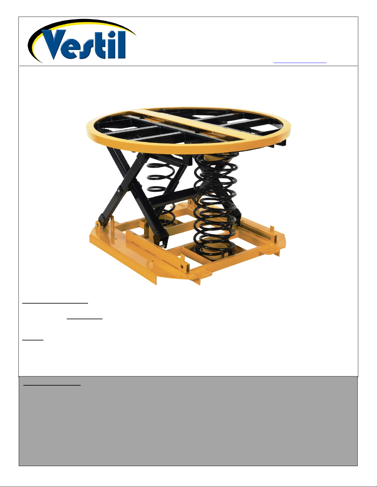
SST-45 Self-Leveling Scissor Table
Assembly, Use, and Maintenance Manual
www.vestilmfg.com e-mail: sales@vestil.com
Receiving instructions:
After delivery, IMMEDIATELY remove the packaging from the product. Inspect the product closely for damage. If damage
is discovered, immediately record a complete description of the damage on the bill of lading. If the product is
undamaged, discard the packaging.
NOTES:
1) Compliance with laws, regulations, codes, and non-voluntary standards applied where the product is used is the
exclusive responsibility of the end-user.
2) VESTIL is not liable for any injury or property damage that occurs from failure to apply either:
a) Instructions in this manual; or b) information provided on labels affixed to the product. Vestil is not responsible for
consequential damages while assembling, installing, using or maintaining this product.
Table of Contents
Product Specifications……………….…………………..…………………………………………………………………………2
Spring Combinations (Diagrams & Load Table)…………………………………………………………………………………2
Signal Words….……………………..……………………………………………………………………………………………... 3
Safe Use Recommendations……………………………………………………………..………………………………………. 3
Assembly Instructions………………………………………………………………………………………………………………4-5
Installing/Removing Springs………………………………………………………………………………………………………. 5
Table Loading Instructions…………………………………………………………………………………………………………6
Inspections & Maintenance……………………………………………………………………………………………………….. 6
Troubleshooting Guide…………………………………………………………………………………………………………….. 6
Labeling Diagram……...……………………………………………………………………………………………………..……. 7
Limited Warranty…...………………………………………………………………………………………………………………. 8
Copyright 2015 Vestil Manufacturing Co. Page 1 of 8
Page 2

Rev. 12/20/2016 SST-45, MANUAL.doc
C B A
Purple
Grey
FRONT
BACK
RIGHT
LEFT
Product specifications:
Dimensions and other product specifications appear in the diagrams and table below.
Model
(Tabletop height)
Springs
compressed
SST-45
91/2 in.
24.1 cm
Spring Combinations:
Three (3) springs are included with this product in order to
optimize performance over a broad range of load weights and
heights. Each spring is marked with a unique color: orange,
grey, or purple. Use the table below to match the weight and
height of your load with the proper complement of springs. Load
weight ranges are given in pounds (lb.); height ranges are given
in inches. Refer to the “Spring Combinations Diagrams” below
when installing or removing springs.
Spring Combinations Diagrams:
O = orange spring only
Back
Height of load in inches
Front
0-400 400-800 800-1200 1200-1600 1600-2000 2000-2400 2400-2800 2800-3200 3200-3600 3600-4000 4000-4400
58-60 O O O O O O OG OG OG OP OP
56-58 O O O O O OG OG OG OG OP OP
54-56 O O O O O OG OG OG OG OP OP
52-54 O O O O O OG OG OG OP OP OP
50-52 O O O O O OG OG OG OP OP OGP
48-50 O O O O O OG OG OG OP OP OGP
46-48 O O O O O OG OG OP OP OP OGP
44-46 O O O O OG OG OP OP OP OGP OGP
42-44 O O O OG OG OG OP OP OGP OGP OGP
40-42 O O O OG OG OP OP OP OGP OGP OGP
38-40 O O O OG OG OP OP OGP OGP OGP OGP
36-38 O O O OG OG OP OGP OGP OGP OGP OGP
34-36 O O OG OG OP OP OGP OGP OGP OGP OGP
32-34 O O OG OP OP OGP OGP OGP OGP OGP OGP
30-32 O O OG OP OP OGP OGP OGP OGP OGP OGP
Orange
spring
B
A
Springs
extended
273/4 in.
70.5 cm
OG = orange and grey
springs
Back
Front
Load weight including pallet/skid in pounds
B
(Base
length)
361/4 in.
92.1 cm
Grey
spring
Orange
spring
C
Rotating ring diameter
(Base
width)
363/4 in.
93.3 cm
103.2 cm
OP = orange and
purple springs
Back
Front
Net
Inside Outside
405/8 in.
435/8 in.
110.8 cm
weight
380 lb.
172.7 kg
Load springs included with this table:
Orange
OPG = Orange, purple
& grey springs
Purple
spring
Orange
spring
Back
Front
Capacity
400-4400 lb.
182-2000 kg
Purple
spring
Orange
& grey
springs
Copyright 2015 Vestil Manufacturing Co. Page 2 of 8
Page 3
Rev. 12/20/2016 SST-45, MANUAL.doc
SIGNAL WORDS:
This manual uses SIGNAL WORDS to indicate the likelihood of personal injuries, as well as the probable seriousness
of those injuries, if the product is misused in the ways described. Other signal words call attention to uses of the
product likely cause property damage. The signal words used appear below along with the meaning of each word:
Each person who assembles, installs, uses, or maintains this product should read the entire manual in advance and
fully understand the directions. If after reading the manual you do not
Identifies a hazardous situation which, if not avoided, WILL result in DEATH or SERIOUS
INJURY. Use of this signal word is limited to the most extreme situations.
Identifies a hazardous situation which, if not avoided, COULD result in DEATH or SERIOUS
INJURY.
Indicates a hazardous situation which, if not avoided, COULD result in MINOR or MODERATE
.
injury
Identifies practices likely to result in product/property damage, such as operation that might
damage the product.
understand an instruction, ask your supervisor
or employer for clarification, because failure to adhere to the directions in this manual might result in serious personal
injury.
Safe Use Recommendations:
We strive to identify all hazards associated with the use of our products. However, material handling is dangerous and
no manual can address every risk. The end-user ultimately is responsible for exercising sound judgment at all times.
Material handling is dangerous. Improper or careless operation of this table might result in serious
personal injuries.
Failure to read and understand the entire manual before assembling, using or servicing the product
constitutes misuse. Read the manual whenever necessary to refresh your understanding of proper use and
maintenance procedures.
DO NOT install the table outdoors or in corrosive environments. ONLY install the table on compacted, improved
surfaces (e.g. concrete) that are level and even. The surface must be capable of supporting the combined weight of
the table and a full capacity load.
DO NOT use the table unless it is in normal operating condition. Inspect the unit as described in the inspection
instructions on p. 6. DO NOT use the machine unless it passes every part of the appropriate inspection or until it is
restored to normal operating condition.
DO NOT use the table to lift people. DO NOT stand on the table frame or climb onto the tabletop.
Always watch the table carefully while applying a load to it.
Avoid pinch points. Pinch points are created as the table rises and lowers do to the pivoting motion of the scissor
legs. NEVER reach into or put any part of your body between the scissor legs.
Always load the table properly (see p. 2). Center and evenly distribute all loads applied to this table.
The tabletop should elevate evenly as weight is removed from it and lower smoothly as weight is applied to it.
Watch for binding or jerky movement and listen for unusual noises. Remove the unit from service if you observe
anything abnormal.
DO NOT apply loads to this table on broken or damaged pallets. Examine each pallet to confirm that no nails
protrude from the surfaces and that all boards are intact. A damaged/broken pallet might interfere with tabletop
rotation. A sudden stop while rotating the tabletop could cause the load to shift or fall.
Lift a load high enough that it is clearly no longer in contact with the tabletop before backing away from the table.
If the table must be moved, completely unload it first.
DO NOT use this table UNLESS all labels are in place & readable (see “Labeling diagram” on p. 7.)
DO NOT modify this product in any way. Modifying the machine automatically voids the limited warranty (see p. 8).
and might make it unsafe to use.
If repairs are necessary, ONLY install manufacturer-approved replacement parts.
Proper use and maintenance are essential for this product to function properly.
Always use this product in accordance with the instructions in this manual.
Periodically lubricate moving parts.
Keep the product clean & dry at all times. Always store the unit inside.
Only use approved replacement parts. To order replacement or spare parts for this equipment, contact the factory.
Copyright 2015 Vestil Manufacturing Co. Page 3 of 8
Page 4

Rev. 12/20/2016 SST-45, MANUAL.doc
Linch
pin Clevis pin
Carousel
Assembling Instructions:
The table is easily assembled and disassembled. However, heavy lifting is required and it is, therefore, strongly
recommended that at least 2 people work together to assemble and disassemble the table. [NOTE: Numbers in
parentheses () in steps 1-8 below correspond to item numbers.]
be deployed and the appropriate spring combination must be installed before it can be used.
Tabletop latch
The unit is shipped as shown below. The tabletop must
Tabletop plug
Shock absorber
Clevis pin + linchpin
Spring receiver
Fork pocket
Step 1: Remove the (yellow) carousel from the tabletop. Then, remove the
linchpin and clevis pin to release one end of the shock absorber from the shock
bracket as shown below.
Step 2: Remove the tabletop plug from the
opening above the spring receiver. Turn
the plug and lift it out the top of the table.
Step 3: Lift the tabletop latches and lift the tabletop as high as it will go. Then, install the clevis pin into one of the 2 pin holes in
the roller channel as shown below. The clevis pin prevents the scissor legs from moving. After installing the pin, slowly lower the
table until the roller firmly rests against the clevis pin.
Lift latches while raising tabletop
Linchpin
Roller
pin
Clevis
pin
Roller
rests
against
clevis
pin
Roller
Clevis
pin
Copyright 2015 Vestil Manufacturing Co. Page 4 of 8
Page 5

Rev. 12/20/2016 SST-45, MANUAL.doc
Step 4: Insert the bottom of the spring (each spring is
painted with a unique color near the bottom end as shown
on p. 2) into the spring receiver. Insert the base of the
spring between the frame and the spring-retaining tab.
Step 5: Compress the spring by pressing down on the
second or third loop (not the top of the spring) and
slide it under the tabletop.
Spring properly
seated inside receiver
and plug reinstalled.
Spring
receiver
Spring-retaining tab
Step 6: Make sure that the top of the spring
is properly seated inside the upper spring
receiver; then remove the clevis pin.
Step 7: Press the tabletop down until the latches catch; then pull
out the free end of the shock absorber and attach it to the shock
bracket using the clevis pin and linchpin.
Extend shock:
Step 8: Reinstall the carousel (unit shown below
with all 3 springs installed).
Fasten shock to bracket:
Bracket
Linchpin
Clevis
pin
Installing/Removing Springs:
Before loading the table, use the “Spring Combinations Table” on
p. 2 to determine if more than just the orange spring is required. If
the height and weight of a particular load requires adding springs,
determine which springs are necessary as well as their proper
placement as indicated in the “Spring combinations diagram” on p.
2. To install either the grey or purple spring:
1. Remove the appropriate
tabletop plug;
2. Insert the spring through
the opening. Make sure
that the spring is seated
properly;
3. Then, reinsert the plug and
turn it as far as possible
(the fins of the plug will
contact stops) to secure
the plug in place.
4. Look underneath the
tabletop to confirm that the
spring is properly seated
as shown in the
photograph to the right.
Spring seated inside upper
receiver with plug reinstalled.
Copyright 2015 Vestil Manufacturing Co. Page 5 of 8
Page 6

Rev. 12/20/2016 SST-45, MANUAL.doc
Table Loading Instructions:
Loading -- When using the spring table to load a pallet, always center the pallet on the table and center the load on
the pallet. Distribute weight evenly on the pallet. For instance, if you are palletizing boxed items, add boxes in layers.
Complete each layer before adding boxes to higher layers. Be careful while removing the loaded pallet from the table.
Insert the forks of your lift truck through the pallet and slowly raise the forks. The table will rise at the same time.
Continue to raise the forks until the tabletop is several inches below the bottom of the pallet before backing away from
the table.
Unloading -- If you use the table to support a pallet while unloading it, apply the loaded pallet to the tabletop by
slowly lowering the forks of your lift truck. Continue to slowly lower the forks as the springs compress under the load.
Watch the pallet closely. When a gap appears between the top side of the forks and the pallet deck boards, stop
lowering the forks. Raise the forks just enough to almost close the gap; then slowly back away from the pallet. Adjust
the elevation of the forks if necessary to avoid over-compressing or under-compressing the springs. Unload the pallet
evenly. Remove items in layers by completely unloading each layer before removing items from lower layers.
Inspections & Maintenance:
If any of the inspections described below reveal problems, tag the unit “Out of Service”. Restore the machine to
normal operating condition BEFORE using it again.
A. Before each use, inspect the following components. Each component must be in normal operating condition. To
establish normal operating condition, make a thorough record of the appearance, sound, and function of the various
parts of the table when you first assemble it. Compare later observations to the record to determine whether the
machine is in normal operating condition.
1. Frame: examine the frame, scissor legs, roller channels, and carousel. Look for damaged welds, warps, cracks,
or other deformations.
2. Casters: examine each caster. Confirm that casters are not severely worn, swivel freely, and that the brakes
firmly engage the wheels.
3. Springs: apply a test load to the table that is appropriate for each spring combination. The tabletop should move
smoothly without binding or jerking. While applying the test loads, listen for unusual sounds.
4. Fasteners: check bolts and nuts. Make sure all fasteners are tightly connected.
5. Roller bearings: rotate the carousel. Watch and listen to the carousel as it rotates. If unusual noise is produced,
or if the carousel binds, wobbles, or lurches, remove it and examine the roller bearings. Rotate each bearing to
determine it requires lubrication. Replace all bearings that are significantly worn. Clean the underside of the
carriage where the bearings make contact with it to remove debris that might interfere with them.
B. At least once per month:
1. Wiring: inspect the electrical system and look for loose connections and damage.
2. Clean the machine: remove dirt and other matter from all surfaces.
3. Labels: refer to the “Labeling Diagram” on p. 7. Make sure that all labels are in place and readable.
4. Batteries: remove corrosion from the posts if present.
Troubleshooting guide:
The following table describes the most common issues that occur with these spring tables. If your unit experiences a
problem not included in this guide, contact the factory for assistance.
Issue: Explanation Remedy
1) When a load is applied to the table,
the carousel rotates on its own.
2) The carousel produces a lot of noise
while it rotates
3) The tabletop lowers too much when a
load is applied.
4) The tabletop does not lower enough
when a load is applied.
5) The tabletop bounces or feels spongy
when pressed.
a) Table is not level. a) Determine the state of levelness and
adjust the position of the frame to level
the unit.
b) 1 or more carousel bearings need to be
lubricated or replaced.
c) The load applied exceeds the weight
limit of the spring combination.
d) The load exceeds the maximum
capacity of the table (4,400 lb.)
e) The spring combination is too strong for
the load applied.
f) The shock absorber is malfunctioning. f) Examine the shock absorber. Replace
b) Rotate each of the bearings to
determine which are noisy and/or do not
rotate smoothly. Lubricate bearings. If a
bearing appears to be significantly worn,
replace it.
c) Remove the load and select the proper
spring combination for the load. (See
“Spring Combinations Table”.)
d) Reduce the load until it is within the
capacity of the table.
e) Remove the load and select the proper
spring combination for the load. (See
“Spring Combinations Table”.)
it if it is damaged or leaking.
Copyright 2015 Vestil Manufacturing Co. Page 6 of 8
Page 7

Rev. 12/20/2016 SST-45, MANUAL.doc
Labeling diagram:
The table should always be labeled as shown in the diagram below. Replace all labels that become damaged or
unreadable.
B
D
E
F
A
C
A: Label 207
B: Label 287
E: Label 204
C: Label 824
D: Label 208
F: Label 269
Copyright 2015 Vestil Manufacturing Co. Page 7 of 8
Page 8

Rev. 12/20/2016 SST-45, MANUAL.doc
LIMITED WARRANTY
Vestil Manufacturing Corporation (“Vestil”) warrants this product to be free of defects in material and workmanship
during the warranty period. Our warranty obligation is to provide a replacement for a defective original part if the part
is covered by the warranty, after we receive a proper request from the warrantee (you) for warranty service.
Who may request service?
Only a warrantee may request service. You are a warrantee if you purchased the product from Vestil or from an
authorized distributor AND Vestil has been fully paid.
What is an “original part”?
An original part is a part used to make the product as shipped to the warrantee.
What is a “proper request”?
A request for warranty service is proper if Vestil receives: 1) a photocopy of the Customer Invoice that displays the
shipping date; AND 2) a written request for warranty service including your name and phone number. Send requests
by any of the following methods:
Mail Fax Email
Vestil Manufacturing Corporation (260) 665-1339 sales@vestil.com
2999 North Wayne Street, PO Box 507 Phone
Angola, IN 46703 (260) 665-7586
In the written request, list the parts believed to be defective and include the address where replacements should be
delivered.
What is covered under the warranty?
After Vestil receives your request for warranty service, an authorized representative will contact you to determine
whether your claim is covered by the warranty. Before providing warranty service, Vestil may require you to send the
entire product, or just the defective part or parts, to its facility in Angola, IN. The warranty covers defects in the
following original dynamic components: motors, hydraulic pumps, electronic controllers, switches and cylinders. It
also covers defects in original parts that wear under normal usage conditions (“wearing parts”), such as bearings,
hoses, wheels, seals, brushes, and batteries.
How long is the warranty period?
The warranty period for original dynamic components is 90 days. For wearing parts, the warranty period is also 90
days. The warranty periods begin on the date when Vestil ships the product to the warrantee. If the product was
purchased from an authorized distributor, the periods begin when the distributor ships the product. Vestil may, at its
sole discretion, extend the warranty periods for products shipped from authorized distributors by up to 30 days to
account for shipping time.
If a defective part is covered by the warranty, what will Vestil do to correct the problem?
Vestil will provide an appropriate replacement for any covered part. An authorized representative of Vestil will contact
you to discuss your claim.
What is not covered by the warranty?
1. Labor;
2. Freight;
3. Occurrence of any of the following, which automatically voids the warranty:
Product misuse;
Negligent operation or repair;
Corrosion or use in corrosive environments;
Inadequate or improper maintenance;
Damage sustained during shipping;
Collisions or other incidental contacts causing damage to the product;
Unauthorized modifications: DO NOT modify the product IN ANY WAY without first receiving written
authorization from Vestil. Modification(s) might make the product unsafe to use or might cause excessive and/or
abnormal wear.
Do any other warranties apply to the product?
Vestil Manufacturing Corp. makes no other express warranties. All implied warranties are disclaimed to the extent
allowed by law. Any implied warranty not disclaimed is limited in scope to the terms of this Limited Warranty.
Copyright 2015 Vestil Manufacturing Co. Page 8 of 8
 Loading...