

Page 1
STEEL STORAGE SHED MODEL SHED-5932-F
ASSEMBLY MANUAL
VESTIL MANUFACTURING CORP.
2999 NORTH WAYNE STREET, P.O. BOX 507, ANGOLA, IN 46703
TELEPHONE: (260) 665-7586 -OR- TOLL FREE (800) 348-0868
FAX: (260) 665-1339
URL: WWW.VESTILMFG.COM EMAIL:
SALES@VESTIL.COM
NOTE: Compliance with regulations, codes, and/or standards actually incorporated into law enforced in
the location where the product is used is exclusively the responsibility of the end user.
Copyright 2012 Vestil Manufacturing Corp. Page 1 of 12
Page 2
PRODUCT INTRODUCTION
Thank you for purchasing a SHED-5932-F model Steel Storage Shed. Each shed
includes the following features: panels protected from rust by zinc-plating; angled roofline
to prevent rain accumulation on the roof; lockable door latch that incorporates a 5/16in.
opening for a padlock (not included); and an open-floor design. Although assembly and
use are relatively intuitive, all persons who might participate in the assembly or use of this
product must familiarize themselves with the instructions provided in this manual.
Product Name
SHED-5932-F
Overall Dimensions Height x Width x
Depth in inches (metric equivalents)
Additional shed specifications appear in the table below:
Door Opening Dimensions Height x
Width in Inches (metric equivalents)
59 x 32 x 78¾
(149.9cm x 81.3cm x 200cm)
72½ x 30½
(184.2cm x 77.5cm)
Net Weight in
Pounds (kg)
88
(~40kg)
SAFETY PRINCIPLES
Vestil Manufacturing Corp. recognizes the critical importance of workplace safety. Employers are
responsible for instructing employees to assemble and use the product properly. Employees and any
other person, who participates in the assembly of this product or uses the shed must read and
understand every instruction BEFORE assembling or using it. If you do not understand an instruction,
ask your supervisor or employer for clarification.
Although Vestil diligently strives to identify foreseeable hazardous situations that might arise during the
course of assembly or use, this manual cannot address every conceivable danger. The end-user must exercise
sound judgment at all times. Vestil is not liable for any injury or property damage that occurs as a consequence
of failing to apply the assembly or use instructions that appear in this manual.
This manual classifies personal injury risks and situations that could lead to property damage with SIGNAL
WORDS. These signal words announce an associated safety message. The reader must understand that the
signal word chosen indicates the seriousness of the described hazard.
Identifies a hazardous situation which, if not avoided, WILL result in DEATH or SERIOUS
Identifies a hazardous situation which, if not avoided, COULD result in DEATH or
Indicates a hazardous situation which, if not avoided, COULD result in MINOR or
Identifies practices likely to result in product/property damage, such as operation that might
INJURY. Use of this signal word is limited to the most extreme situations.
SERIOUS INJURY.
MODERATE injury.
damage the shed.
SAFETY GUIDELINES
Failure to read and understand the instructions included in this manual before assembling or using the
shed constitutes misuse of the product.
Electrocution might result if the shed contacts electrified wires. Reduce the likelihood of
electrocution by applying common sense.
DO NOT assemble or install the shed in an area where contact with electrified wires is possible.
DO NOT use the shed as a shelter during electrical storms.
Reduce the likelihood of serious personal injuries that could result from improper of careless
assembly or use of this product:
DO NOT use a structurally damaged shed. Periodically inspect the shed for damage. DO NOT use the shed if it is
structurally damaged.
Follow the assembly instructions in this manual; the shed might be unsafe to use if improperly or carelessly
assembled.
DO NOT stack items on top of the shed. The roof panel will not support much weight, and because the roof is angled,
items will slide off of the roof.
DO NOT climb on or allow others to climb on the shed.
Copyright 2012 Vestil Manufacturing Corp. Page 2 of 12
Page 3
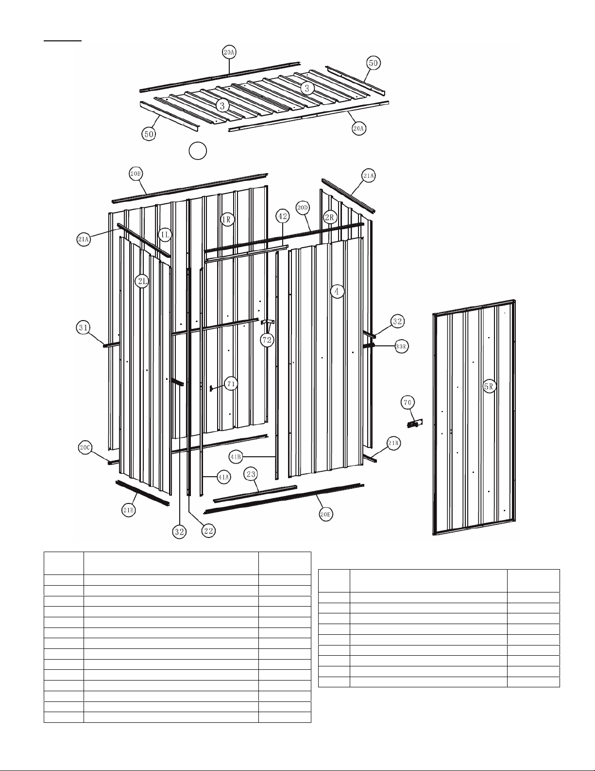
FIG. 1: Exploded parts diagram
17
Part
no.
1L 78in. x 30¼ in. rear wall panel 1
1R 78in. x 30¼ in. rear wall panel 1
2L (74.8 – 77.9)in. x 30.3in. side wall 1
2R (74.8 – 77.9)in. x 30.3in. side wall 1
5R 72.6in. x 30.3in. door 1
20A 59.4in. front/back roof channel 2
20B 59.4in. rear wall (top) channel 1
20C 59.4in. rear wall (bottom) channel 1
20D 59.4in. front wall (top) channel 1
20E 59.4in. front wall (bottom) channel 1
21A 30¼ in. top channel for side panel 1
21B 30¼ in. bottom channel for side panel 1
Description Quantity
3 33.7in. x 30.3 in. roof panel 2
4 74.8in. x 27.9in. front panel 1
Copyright 2012 Vestil Manufacturing Corp. Page 3 of 12
Part
Description Quantity
no.
22 74.7 in. door frame side channel 1
23 30.5 in. door frame bottom channel 1
31 57.4 in. rear wall brace 1
32 28.3 in. side wall brace 1
33R 26.5 in. front wall brace 1
41A 74.7 in. left side door jamb 1
41B 74.7 in.. right side door jamb 1
42 30.5in. doortop jamb 1
50 33.7in. roof side channel 1
Page 4
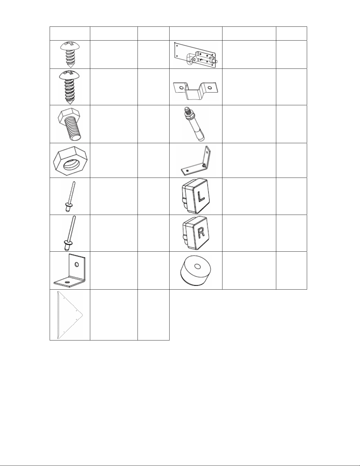
Hardware
Item
Description Quantity Hardware
10mm self-
tapping screw
120
16mm self-
tapping screw
12
5
/16in. – ¾in.
hex head bolt
5
/16in. hex nut 8
8
3mm x 10mm
rivet
6
Item
Description Quantity
Door latch 1
Door latch keeper 1
Sleeve anchor
bolt
Wall bracket 3
L-type channel
cap
8
1
4mm x 10mm
rivet
Anchor bolt
bracket
Reinforcing
bracket
12
8
2
R-type channel
Screw concealing
cap
cover
1
25
Tools required to assemble the shed:
Electric drill (1)
Cordless drill (1)
Measuring tape (1)
Rubber mallet (1)
Adjustable crescent wrench or
5
/16in. crescent wrench (1)
Personal protective equipment: gloves & eyewear
Phillips head screw driver (1)
Drill bits: 10mm masonry drill bit; 8mm bit; 4mm bit; and 3mm bit.
Pencil or marker (1)
Pop rivet gun (1)
6ft. self-supporting step ladder (2)
Copyright 2012 Vestil Manufacturing Corp. Page 4 of 12
Page 5

ASSEMBLY INSTRUCTIONS:
Step 1: Fasten rear panel 1R to panel 1L using 10mm self-tapping screws as depicted in the diagram below. Panels
are shown with the outside surface facing up (corrugations face upwards).
Connect top channel 20B to one side of the panels by either tapping the channel into place with a rubber mallet, or
sliding it into place. Connect bottom channel 20C to the opposite side of the panels. The top of the panels is the side
to which channel 20B is connected. NOTE: Channels 20B and 20C are not symmetrical. The shorter lip of each
channel must be on the outside surface.
20B
Top of rear panels
Short lip
1R
10mm self-tapping screws
1L
Bottom of rear panels
Long lip
Step 2
: Fasten channels 20B and 20C to the rear panels with 10mm self-tapping screws; then fasten channel 31 to
the inside surface of the rear panels with 10mm self-tapping screws.
20B
1R
31
20C
This symbol indicates a place
where a 10mm screw should be
used to fasten channel to panel.
1L
View of inside surface of rear wall with channel
31 installed
20B 31
20C
Fasten channel 38A with the slot
facing the bottom
Top
1L
Copyright 2012 Vestil Manufacturing Corp. Page 5 of 12
1R
20C
Bottom
Page 6

Step 3: Fasten channel pieces 21A and 21B to the side panel 2L. Orient panel 2L so that corrugations face upwards
(outside surface is face up). Slide or tap channel 21B onto the bottom of panel 2L; then fasten the channel 32 to the
panel with three (3) 10mm self-tapping screws. Slide or tap channel 21A into place, but do not fasten it with screws at
this time. Attach channel 32 to the inside surface with three (3) 10mm self-tapping screws.
Top of side panel
2L
and
2R
21A
Fasten channel 32D to panel 2E
with 10mm self-tapping screws
Install a 10mm self-tapping
screw at each location where
this symbol appears EXCEPT
those circled with double dotted
lines
The slot of channel 32D should
face the bottom of the panel
assembly when installed.
32
Bottom of side panel
21B
Step 4
: Connect the 2 front panels 1R and 1L and then fasten channels 20B, 20C and 31 to the panels. Tap or slide
channel 20C into place along the bottom of the panel assembly, and then fasten it with 10mm self-tapping screws.
Fasten channel 31 to the middle of the panel assembly using six (6) 10mm self-tapping screws. Finally, tap or slide
channel 20B into place; then fasten it with 10mm self-tapping screws. Do not install screws at the locations circled
with double dotted lines.
20B
Top of side panels
Fasten the panels together
with 10mm self-tapping
screws
1L
1R
The slot of channel 38B
should face the bottom of
the panel assembly when
installed.
31
Bottom of side panels
20C
Step 5
: Connect roof panels 3 and 3 with 10mm screws. Next, tap or slide channels 20A and 20A to the top and
Install a 10mm self-tapping screw at each
location where this symbol appears EXCEPT
those circled with double dotted lines
bottom of the roof assembly; then apply lip pieces 50 and 50 to the sides of the roof assembly. Fasten the channels
and the lip pieces to the panels with 10mm self-tapping screws. NOTE: A single screw will fasten lip and channel to
the panels at each of the 4 corners as shown in the close-up views of the diagram on p. 7.
Step 5A:
Fasten the panels together with 10mm
self-tapping screws
3
3
Copyright 2012 Vestil Manufacturing Corp. Page 6 of 12
Page 7

Step 5B: First, tap or slide the channels 20A and 20A
onto the top and bottom of the panel assembly; then lay
the lip pieces 50 and 50 in place on each side of the
panel assembly. Fasten the channels and lip pieces to the
panels with 10mm self-tapping screws.
Channel
Roof Panel
Lip
piece
20A
50
Step 6: Assemble the front wall.
Step 6A: Attach the front wall top channel (20D), front wall bottom channel (20E), door jamb (41B), and the
front wall brace (33R) to the front panel (4) with 10mm self-tapping screws.
4 41B
50
20A
Install a 10mm selftapping screw at each
location where this
symbol appears.
20E
Step 6B: Complete the door frame.
20D
42
41A
41A
23
Install this screw
when shed fully
assembled
20E
20D
42
41B
41B
4
20E
Copyright 2012 Vestil Manufacturing Corp. Page 7 of 12
Page 8

Step 7: Fasten the door to the front wall assembly. (NOTE: The installation instructions that appear below show the
door fastened to the right side of the door opening; the door can be installed on the left side as well. See “Alternative
Door Installation” on p.12.)
Fasten the door hinges to
the door frame of the front
wall assembly with 4mm x
10mm rivets.
Fasten the door latch to the door with
3mm x 10mm rivets.
OR
2E
Fasten the door latch to the door
with 10mm screws
Copyright 2012 Vestil Manufacturing Corp. Page 8 of 12
Page 9

Step 8: Fasten the front, rear, and side panels together. First fasten the side walls to the rear wall with 10mm screws;
then fasten the front wall to the rest of the assembly with 10mm screws.
2L
Clamp the side panel 2L between jamb
piece 41A and channel 22 by fastening 41A
and 22 with six 16mm screws.
41A22
10mm
16mm
22
41A
2L
2L
1L
1R
2R
This symbol represents
a 10mm self-tapping
screw. Install a screw at
each location where this
symbol appears.
4
5R
20C
-OR-
41A 41A
21B
71 71
Fasten door latch keeper with 3mm x
10mm rivets
Copyright 2012 Vestil Manufacturing Corp. Page 9 of 12
Fasten latch keeper to door jamb with
Page 10

Step 9: Install the door latch keeper and wall-reinforcing brackets; then anchor the shed to a concrete surface.
Installation of wall-reinforcing
brackets
10mm
screw
Fasten the latch keeper to the door
frame with either 10mm screws
71
72
Overhead, cut-away view of shed
Anchor bolt and anchor bolt bracket installation
These symbols
represent anchor bolt
brackets
DOOR
-OR-
3mm x 10mm rivets
71
Concrete
Copyright 2012 Vestil Manufacturing Corp. Page 10 of 12
Page 11

Step 10: Cover the ends of the wall-reinforcing channels in the doorway with the L-type and R-type channel caps.
Copyright 2012 Vestil Manufacturing Corp. Page 11 of 12
Page 12

Alternative Door Installation
Flip the door over and position it in the door frame as desired. Align the frame wing of each hinge with the door jamb
(41A) and drill holes in the jamb that match the holes in the wings. Before fastening the door to the jamb, tap the
hinge pins out of the hinge knuckle and reinsert them from the top; then fasten the frame wings of the hinges to the
door jamb with 10mm screws or 4mm x 10mm rivets. Fasten the latch keep to the (opposite) door jamb (41B) with
either 10mm screws of 3mm x 10mm rivets.
Remove hinge pin and reinsert
it from the top
71
41B
Copyright 2012 Vestil Manufacturing Corp. Page 12 of 12
71
41B
 Loading...