

Page 1
04/09/07 28-126-123
VESTIL MANUFACTURING CORP.
2999 N. Wayne St., Angola, IN 46703
Ph: 260-665-7586 · Fax: 260- 6 65-1339
E-mail: sales@vestil.com · Website: www.vestil.com
OWNER’S
MANUAL
MODEL - SELF SUPPORTING BRIDGE CRANE
Serial number ____________
Assembly / Installation Instructions ………………..… 2
Anchoring Instructions …………………….……….. .. 3
Routine Maintenance & Safety Checks ……………… 4
IMPORTANT NOTES, WARNINGS AND SAFETY INSTRUCTIONS
Ensure that all employees understand and follow the following.
* Failure to read and understand this owner’s manual before using or
servicing the Self Supporting Bridge Crane constitutes a misuse of the
product. All persons who will install, use, or care for this product must
be familiar with this material.
o The load must be removed before any work is performed on the Self
Supporting Bridge Crane.
o Ensure that all information / safety / warning labels stay in place and are
legible.
o Do not use the Self Supporting Bridge Crane if any damage or unusual
noise is observed.
o Always watch the hoist and load carefully when the hoist & trolley are in
operation.
o The Self Supporting Bridge Crane must be lagged to the floor before
operating.
o The Self Supporting Bridge Crane is intended for installation / use only on
compacted, improved surfaces. Six inch minimum reinforced concrete in
required.
♦ Do not perform any modifications to the Self Supporting Bridge Crane
without the manufacturer’s approval. Failure to receive authorization for
changes to the equipment could void the warranty.
♦ Maintenance and repairs are to be done only by personnel qualified to
perform the required work. Consideration will not be given for warranty
repair charges without prior written authorization by the manufacturer.
♦ Do NOT use for lifting transporting or supporting humans.
♦ Do NOT use crane as a method of grounding equipment.
Inspection & Testing Procedures (hoists) ...…….…… . 5- 6
Exploded Structural Parts Drawing & BOM ………... 7-8
Warranty …………………………………….……..…. 9
WHEN ORDERING
REPLACEMENT PARTS:
We take pride in using quality
parts on the equipment we
manufacture. We are not
responsible for equipment
problems resulting from the use
of unapproved replacement
parts.
To order replacement or
spare parts for this equipment,
contact the factory.
In any communication with
the factory please be prepared
to provide the machine’s serial
number, which is indicated on
the machine dataplate.
RECEIVING INSTRUCTIONS
It is possible that this product
could incur damage during
transit.
Inspect the unit closely when
it arrives. If you see evidence
of damage or rough handling to
either the packaging or to the
product when it is being
unloaded, immediately
note of it on the Bill Of Lading!
It is important that you
remove the product’s packaging
upon its arrival to ensure that
there is no concealed damage
or to enable a timely claim with
the carrier for freight damage.
Also verify that the product
and its specifications are as
ordered.
make a
ESTIL MFG. CO. 1
V
Page 2

concrete anchors, installation, 1005.doc
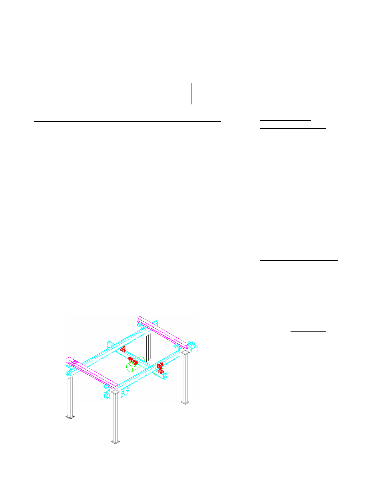
INSTALLATION (AND/OR ASSEMBLY) INSTRUCTIONS – SELF SUPPORTING BRIDGE CRANE
Review this entire page before installing the Self Supporting Bridge Crane.
Consult the factory in the event there are any questions or problems at the time of installation, or for
information regarding optional features not covered by the owner’s manual.
The Self Supporting Bridge Crane must be removed from the shipping wood and securely anchored to a
concrete surface before use!
• Modifications or additions to the Self Supporting Bridge Crane without prior manufacturer’s authorization
may void the Crane’s warranty. The addition of ancillary equipment to the Self Supporting Bridge Crane may
necessitate that its load capacity be reduced.
• The installation must be made so that it complies with all the regulations applicable to the machine and its
location. The end-user must verify that the supplied equipment is installed so it will be suited to the
environment in which it will be used.
• Installation must be performed by suitably trained personnel with access to the appropriate equipment. The
electrical aspects of the installation should be performed by an electrician.
---------------------------------------------------------------------------------------
For a typical installation of a standard Self Supporting Bridge Crane you will need the following:
1. A fork truck or hoisting means to unload the Self Supporting Bridge Crane from the freight truck and set it
into place.
2. A smooth, level, and adequately strong concrete surface on which to mount the Self Supporting Bridge
Crane.
3. Concrete anchors, a masonry drill, a masonry bit, hand tools, grout, and steel shims. Consult the building’s
architect or facility engineer to determine the best size and type of hardware with which to anchor the
machine to the floor.
4. An appropriate power supply circuit and electrical disconnect matching the motor voltage and current
requirements. The end-user is responsible for supplying the branch circuit’s required ground fault and shortcircuit protection.
---------------------------------------
To install a standard Self Supporting Bridge Crane:
1. Anchor the frame to the floor through the 11/16” holes located in the base plates.
2. Shim and/or grout under the full length of the frame sides.
3. Make permanent connection to the power supply, using an appropriate wiring method.
4. Clean up any debris, and verify that all of the information/safety/warning labels are in good condition.
2 of 9 Vestil Mfg Co / T&S Eqpt Co
Page 3
concrete anchors, installation, 1005.doc
INSTALLING MASONRY ANCHORS
The most important factor in choosing the proper anchor is the type of load it will carry. Shear loads are caused when the
weight of the fixture exerts force parallel to, or along, the surface of the concrete. Tensile loads are caused when the fixture
exerts force perpendicular to, or away from, the concrete surface.
Because precise knowledge of the condition of concrete at a given location is typically lacking, the standard recommendation is
that the anchor you choose should be rated for about four times the load’s weight it will carry if it will bear a static load, and eight
times the load’s weight if it will carry a dynamic or impact load. Static loads are loads that merely sit or hang without ever
experiencing a change in load conditions. Impact, or dynamic, loads have forces that vary in some way, such as when a load is
driven across an edge-of-dock dockleveler or a speed bump.
The holding power of any anchor depends on: the quality of the concrete -- if the concrete is old and crumbly, the holding
power of the fastener will be reduced, and; its position -- if the anchor is placed near the edge of the concrete, or if two anchors
are placed too close together, the force generated by the anchor might break the concrete.
* An anchor should be placed no closer to the edge of the concrete than the distance equal to five times the anchor’s width .
Therefore, a ½" diameter anchor should be no closer than 2½" (½” times five) from the edge of the concrete. Also, two anchors
should never be placed closer than ten times the anchor’s width from each other. In other words, two ½" anchors should be at
least 5" (½" x ten) apart.
♦ Two types of one-piece, mechanical expansion anchors are popular.
Sleeve anchors have a steel sleeve on the shank, split at the bottom so it can expand. The bolt has a cone-shaped plug at the
base, and a nut on the top. When you place the anchor in the hole and tighten the nut, it draws the bolt upward, pulling the plug
into the sleeve and expanding it against the hole. Once installed, sleeve anchors cannot be removed. They are available in a
variety of head styles, however -- a removable hex head, an acorn nut, or either round- or flat-head screws.
The shank of a wedge anchor is similar to a sleeve anchor -- a solid shank, threaded at the top and with a cone-shaped plug at
the bottom. But the shank of a wedge anchor is grooved on opposite sides. In each groove is a rectangular shank with a spadeshaped wedge on the end. As the nut on top is tightened, the washer pushes the rectangular shanks down, which spreads the
wedges over the plug. A wedge anchor cannot be removed once it is installed. Wedge anchors always have a hex head screw with a
washer so the material can be removed and reinstalled.
* As a rule, use sleeve anchors when working with soft concrete or installing them in the mortar joints between block or
brick. Also use sleeve anchors when you suspect that the concrete may have voids in it. Sleeve anchors have a larger bearing
surface than wedge anchors. Use wedge anchors for maximum holding power in hard concrete.
♦ Once the proper type of anchor is determined, select the size of fastener that is closest to the size of the anchoring hole in the
product. Anchoring products’ specifications vary from one manufacturer to the next -- if the manufacturer's installation instructions
differ from the information in this document, always follow the manufacturer's instructions. When drilling a hole for a masonry
screw, it is a good idea to utilize the special bit sold by the screw manufacturer. Proper hole sizing is critical for optimal holding
power. Never use a dull bit, because it tends to produce a larger hole than the same size of sharp bit. When drilling large holes in
masonry, it is much easier and more accurate to start with a smaller bit and step up
protection and a dust mask should be worn when drilling and cleaning the holes.
• To install wedge or sleeve anchors, first position the material you want to anchor. Mark the
locations of the product’s anchor holes on the concrete. The product can be left in place if
there is adequate clearance to allow for drilling the holes. Use a hammer drill to drill the holes
in the concrete at the product’s bolt hole location. Make sure the holes are the specified
diameter for the anchor that you plan to use, and at least ¼" deeper than the length of the
anchor. Blow the dust out of the drilled holes with compressed air or a blow-out bulb. Place
the product over the anchor holes and insert the anchors into the holes. Use an appropriatelysized washer between the bolt head and the product if necessary to prevent the product’s hole
from eventually pulling over the bolt head. Tighten a sleeve anchor two to three turns to
expand it. Tighten a wedge anchor three to five turns. The anchor manufacturer’s instructions
might specify that the anchor is to be tightened with a torque wrench to a certain number of
foot-pounds.
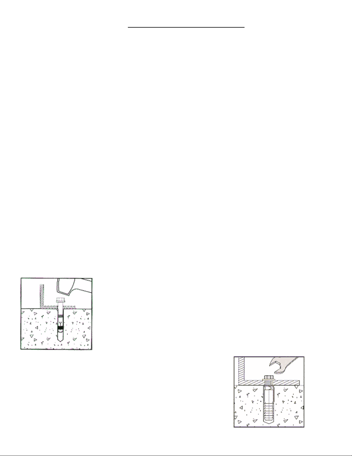
• Installing a two-step mechanical anchor: For a two-step anchor, tap the
anchor into the hole, then position the item being mounted and install the
fastener. Again, use washers if necessary if there is a possibility that the product
could eventually pull off of the bolt head. Tighten the fastener until its head is
fully seated against the mounted item and secure in the hole. Do not over tighten
it, or you might break the fastener or ruin the anchor’s bond with the concrete.
Note: To determine the proper type of concrete fastener to use for a specific
application, consultation with the building’s architect or facility engineer
is recommended.
gradually to the required bit diameter. Eye
3 of 9 Vestil Mfg Co / T&S Eqpt Co
Page 4

concrete anchors, installation, 1005.doc
OPERATION INSTRUCTIONS – SELF SUPPORTING BRIDGE CRANE
o Ensure that all employees involved in the operation of this Self Supporting Bridge Crane understand and follow
these instructions!
The standard Self Supporting Bridge Crane is suitable for use indoors in most non-classified locations. It is intende d
to be used to lift and move stable, evenly-distributed, non-hazardous materials loads.
Loading:
Note: The addition of any ancillary equipment to the Self Supporting Bridge Crane by third parties must be taken into
account when determining the maximum working load.
Warning: Do not exceed the Self Supporting Bridge Crane’s load ratings. Injury to personnel or permanent damage to
the Self Supporting Bridge Crane could result from exceeding the listed capacity.
Operation:
Inspect the Crane, Hoist and Trolley function daily.
Warning: Keep all personnel clear of the machine when it is in operation. Be certain no part of any person or o bject is
under any part of the crane or load before lowering the unit.
Caution: Always carefully watch the crane and any load on it when it is in operation.
The Self Supporting Bridge Crane is furnished with a constant-pressure (dead-man style) pushbutton control.
Pressing the “UP” pushbutton or foot switch will turn on the power unit to raise the platform. The platform will
raise only while the control is pressed. Upon releasing the control, the platform will stop and hold its position.
Pressing the “DOWN” pushbutton or foot switch will energize the lowering valve to allow the platform to descend by
gravity (the motor does not run). Again, releasing the control will stop the platform movement, and the unit will hold
its position.
Caution: Never use the Self Supporting Bridge Crane if any damage or unusual noise is observed, if it is in need of
repairs, or if it seems to be malfunctioning. Notify your supervisor or maintenance personn el if you notice anything out
of the ordinary.
Ensure that all information/safety/warning labels stay in place and are legible. Refer to the labels page in this
manual.
4 of 9 Vestil Mfg Co / T&S Eqpt Co
Page 5

concrete anchors, installation, 1005.doc
INSPECTION INSTRUCTIONS
Per OSHA Regulations 1910.179 and American Society of Mechanical Engineers (A.S.M.E.) B30.17 "Overhead and
Gantry Cranes.", all gantry cranes should have an:
1910.179(j)(1)(i) Initial inspection - Prior to initial use all new and altered cranes shall be inspected to insure
compliance.
Besides that, for gantry cranes in regular service, there are two general classifications of inspections based upon the
intervals at which the inspection should be performed. The intervals in turn are dependent up on the nature of the critical
components of the crane and the degree of their exposure to wear, deterioration, or malfunction. The two general
classifications are herein designated as "frequent" and "periodic" with respective intervals between inspections as defined
below:
1910.179(j)(1)(ii)(a) Frequent inspection - Daily to monthly intervals.
1910.179(j)(1)(ii)(b) Periodic inspection - 1 to 12 month intervals.
1910.179(j)(2) Frequent Inspection
The following items shall be inspected for defects at intervals as defined above or as sp ecifically indicated, including
observation during operation for any defects which might appear between regular inspections. All deficien cie s such as
listed shall be carefully examined and determination made as to whether they constitute a safety hazard:
• All functional operating mechanisms for maladjustment interfering with proper operation. Daily.
• Hooks with deformation or cracks. Visual inspection daily; monthly inspection with a certification record which
includes the date of inspection, the signature of the person who performed the inspection and the serial number,
or other identifier, of the hook inspected.
• Hoist chains, including end connections, for excessive wear, twist, distorted links interfering with proper function,
or stretch beyond manufacturer's recommendations. Visual inspection daily; monthly inspecti on with a certification
record which includes the date of inspection, the signature of the person who performed the inspection
and an identifier of the chain which was inspected.
• All functional operating mechanisms for excessive wear of components.
• Rope reeving for noncompliance with manufacturer's recommendation.
1910.179(j)(3) Periodic Inspection
Complete inspections of the crane shall be performed at intervals as generally defined above, depending upon its activity,
severity of service, and environment, or as specifically indicated below. These inspections shall include the requi rements
of the frequent inspection stated above and in addition, the following items. All deficiencies such as listed shall be
carefully examined and determination made as to whether they constitute a safety hazard:
• Deformed, cracked, or corroded members.
• Loose bolts or fasteners.
• Cracked or worn hoist.
• Worn, cracked or distorted parts such as pins, bearings, shafts, gears, rollers, locking and clamping devices.
• Load, wind, and other indicators over their full range, for any significant inaccuracies.
• Gasoline, diesel, electric, or other power plants for improper performance or noncompliance with applicable safety
requirements. (IF APPLICABLE)
• Excessive wear of chain drive sprockets and excessive chain stretch.
5 of 9 Vestil Mfg Co / T&S Eqpt Co
Page 6

concrete anchors, installation, 1005.doc
TESTING INSTRUCTIONS
OSHA also requires two classifications of testing to be performed [per OSHA Regulations 1910.179(k)].
These two testings are:
1910.179(k)(1) Operational tests
1910.179(k)(2) Rated load test
1910.179(k)(1) Operational Tests
(i) Prior to initial use all new and altered cranes shall be tested to insure compliance with this section including the
following functions:
(a) Hoisting and lowering.
(b) Trolley travel.
(c) Bridge travel.
(d) Limit switches, locking and safety devices.
(ii) The trip setting of hoist limit switches shall be determined by tests with an empty hook traveling in increasing
speeds up to the maximum speed. The actuating mechanism of the limit switch shall be located so that it will
trip the switch, under all conditions, in sufficient time to prevent contact of the hook or hook block with any
part of the trolley.
1910.179(k)(2) Rated Load Test
Test loads shall not be more than 125 percent of the rated load unless otherwise recommended by the manufacturer. Th e
test reports shall be placed on file where readily available to appointed personnel.
REFER TO OSHA'S STANDARD 1910.179 FOR COMPLETE INFORMATION ON
OVERHEAD & GANTRY CRANE DEFINITIONS, GENERAL REQUIREMENTS,
HOISTING EQUIPMENT, MAINTENANCE, ROPE INSPECTION,
HANDLING OF THE LOAD, AND
OTHER REQUIREMENTS.
For OSHA publications, including informational materials
on standards and regulations, please contact:
OSHA's Publications Office
200 Constitution Avenue, N.W., Room N3101
Washington, DC 20210
Ph.: (202)219-4667 Fax: (202)219-9266
ALSO REFER TO AMERICAN SOCIETY OF MECHANICAL ENGINEERS (A.S.M.E.)
B30.17 "OVERHEAD & GANTRY CRANES."
For copies of A.S.M.E. B30.17
please contact:
American Society of Mechanical Engineers
Order Department 1-800-THE-ASME
6 of 9 Vestil Mfg Co / T&S Eqpt Co
Page 7

concrete anchors, installation, 1005.doc
EXPLODED PARTS VIEW AND BILL OF MATERIALS – SELF SUPPORTING BRIDGE CRANE
7 of 9 Vestil Mfg Co / T&S Eqpt Co
Page 8

concrete anchors, installation, 1005.doc
BILL OF MATERIALS – SELF SUPPORTING BRIDGE CRANE FRAME LEGS & CROSS BEAMS
Item #: Description Part number Qty.
1 BOLT, 5/8 – 11 UNC x 2 LG A/L 24
2 LOCK WASHERS 5/8” DIA A/L 24
3 NUT, 5/8 – 11 UNC A/L 24
4a FRAME, I – BEAM CROSS SUPPORTS x 140” lg 28-514-131 3
4b FRAME, I – BEAM CROSS SUPPORTS x 200” lg 28-514-132 3
4c FRAME, I – BEAM CROSS SUPPORTS x 260” lg 28-514-133 3
5 FRAME, TUBING UPRIGHT, 5 x 5 TUBE x 160” lg 28-514-130 6
BILL OF MATERIALS – SELF SUPPORTING BRIDGE CRANE BRIDGE CRANE ASSEMBLY
Item #: Description Part number Qty.
1 RAIL (A)
2 RAIL (B)
3 RAIL (C) (ON 30 FOOT RUNWAY ONLY)
4 HANGER KIT
5 TROLLEY ASSEMBLY
6 LOAD BAR
7 END TRUCK
8 END STOP
9 ELECTRIC TROLLEY (HOIST)
10 HARDWARE KIT
8 of 9 Vestil Mfg Co / T&S Eqpt Co
Page 9

concrete anchors, installation, 1005.doc
PRODUCT WARRANTY
ONE YEAR LIMITED WARRANTY
The manufacturer warrants for the original purchaser against defects in materials and wo rkmanship under normal use
for ONE YEAR after date of shipment (not to exceed 16 months after date of manufacture). Any part that is
determined by the manufacturer to be defective in material or workmanship and returned to the factory, shipping
costs prepaid, will be, as the exclusive remedy, repaired or replaced at our option. Labor costs for warranty repairs
and/or modifications are not covered unless pre-approved by the manufacturer or done at the manufacturer’s
facilities. Any modifications performed without prior written approval of the manufacturer may void warranty. This
limited warranty gives purchaser specific legal rights which vary from state to state.
All specifications are subject to change without notice.
LIMITATION OF LIABILITY
To the extent allowable under applicable law, the manufacturer’s liability for consequential and incidental damages is
expressly disclaimed. The manufacturer’s liability in any event is limited to, and shall not exceed, the purchase price
paid. Misuse or modification may void warranty.
Warranty does not cover labor or consequential damages including, but not limited to, business interruption costs, lost
profits, or lost business opportunities.
WARRANTY DISCLAIMER
The manufacturer has made a diligent effort to accurately illustrate and describe their products. However, such
illustrations and descriptions are for the sole purpose of identification, and do not express or imply a warranty that the
products are merchantable or fit for a particular purpose, or that the products will necessarily conform to the
illustrations or descriptions.
The provisions of the warranty shall be construed and enforced in accordance with the Uniform Commercial Code and
laws as enacted in the State of Indiana.
DISPOSITION
Our company will make a good faith effort for prompt correction or other adjustment with respect to any product that
proves to be defective within the Limited Warranty Period. Warranty claims must be made in writing within s aid year.
9 of 9 Vestil Mfg Co / T&S Eqpt Co
 Loading...