

Page 1
T & S Equipment Company
2999 North Wayne St., Angola, IN 46703
Ph: 260-665-9521 Fax: 260-665-1339
E-mail: sales@tseq.com
Website: www.tseq.com
Ergonomic Solutions
Contents
Warnings And Safety Instructions .................... 1
Periodic Maintenance Instructions ................... 1
Receiving Instructions ...................................... 1
Warranty........................................................... 1
Revised 05-02
A company dedicated to solving ergonomic
and material handling problems since 1955.
OWNER'S
MANUAL
AUTO-HITE CARTS • MODEL SCSC
Spring Adjustment ............................................2
Exploded Drawing & Parts List......................... 3
Warning Label Identification .............................4
WARNINGS & SAFETY INSTRUCTIONS
Read owner's manual completely before operating unit!
• Never load the unit unless you are watching it.
• Stand clear from load while loading and unloading.
• Never exceed the maximum loading capacity inscribed on
the nameplate.
• Load unit as uniformly as possible.
• Consult factory for uneven loading.
• Always operate unit on a level surface to insure stability.
• Always apply wheel brakes when unit is not been moved.
• Use caution in moving a loaded cart; avoid obstructions
and floor defects.
• Remove weight before working on unit.
• Never go under platform if there is weight on unit.
• Use only maintenance parts supplied or approved by the
manufacturer.
• Consult factory if adding or performing any modification to
the original equipment.
• Make sure all operator safety labels are in place (p.4).
PERIODIC MAINTENANCE INSTRUCTIONS
Before Each Use Check For The Following:
1.) Structural deformation of legs or deck.
2.) Unusual noise or binding.
RECEIVING INSTRUCTIONS
Every unit is thoroughly tested and inspected prior to
shipment. However, it is possible that the unit may incur
damage during transit. If damage is noticed when unloading,
make a note of it on the BILL OF LADING. Remove all packing
and strapping material, then inspect the unit again for damage.
IF DAMAGE IS EVIDENT, FILE A CLAIM WITH THE
CARRIER IMMEDIATELY!
WARRANTY
This product is warranted for 90 DAYS from date of purchase
to be free of manufacturing defects in material and
workmanship.
This warranty does not cover normal wear of parts or
damage resulting from any of the following: negligent use or
misuse of the product, use or application contrary to
installation instructions, or disassembly, repair or alteration by
any person prior to authorization from a factory representative.
3.) Pivot points for wear.
4.) Rollers for looseness and wear.
5.) Retaining rings at rollers.
6.) Clean off dirt and debris.
7.) Make sure all warning labels are in place and in
good condition. See page 4.
DO NOT USE IF THERE ARE ANY OF THE ABOVE!
AUTO-HITE CARTS
SCSC SERIES
1
Page 2

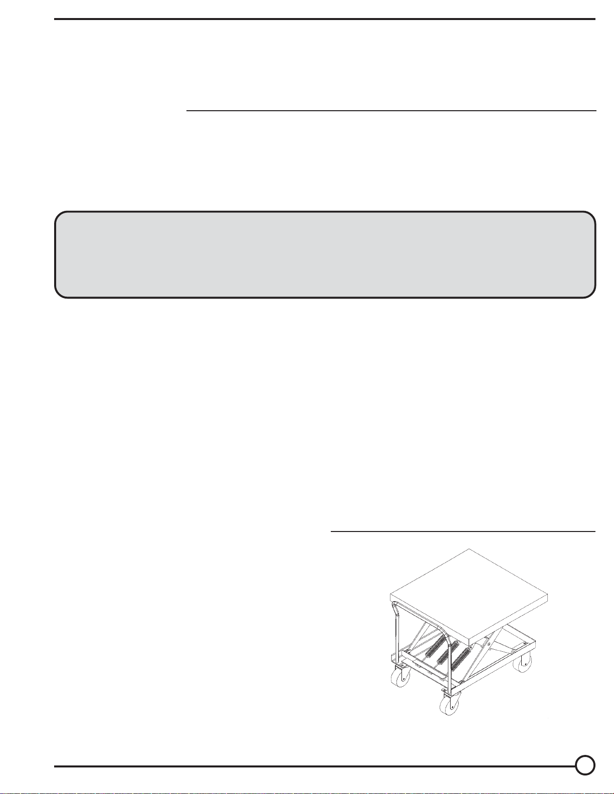
SPRING SCISSORS CART ADJUSTMENT PROCEDURES
GENERAL OPERATION:
Extension springs are attached to the scissors leg assembly. The springs are
arranged to extend as the platform height decreases. As the table is loaded
(platform height decreases) the springs extend, thus increasing the load
carrying capacity of the springs and subsequently counter balancing the load
on the table. By changing the length of the spring, the amount of load to be
counterbalanced can be varied.
ADJUSTMENT PROCEDURES:
1) Determine the approximate total weight of load the weight of the load per
layer being loaded/unloaded. The platform will travel consistently if the load
per layer is at least 10% of the total load. (ie 500 lbs. total load = 50 lbs. per
layer) If your load is less than 10% the platform may into have the same
distance travel per layer for each layer loaded/unload. As with the adjustment,
the best way to establish this is by trial and error.
2) Locate the spring assembly (PT# 01646001) bolt head. This is located on
the cart frame below the push handle.
3) With the full load on the platform (WARNING! Do Not Exceed the Rated
Capacity of the Unit), adjust the spring assembly bolts (CAUTION! Always
Equally Turn Each Bolt) until the platform is just touching the lowered height
stops. This can be checkered by pushing down on the load or lightly lifting the
load (Be Sure NOT to have Hands Under Platform). Rotate the bolts
clockwise to increase the load carrying capacity and counterclockwise to
decrease the load carrying capacity of the springs. This should provide an
even travel per layer of load. Repeat this procedure for each load change.
NOTE: The table height can be adjusted within the full travel by adjusting the
springs to limit or increase the table travel.
2
Page 3

13
PARTS IDENTIFICATION
SCSC SERIES AUTO-HITE CARTS
17
18
19
16
15
14
8
8
7
1
2
ITEM NO.
1
2
3
4
5
6
7
8
9
10
11
12
13
14
15
16
17
18
19
A/L
Available at local hardware store
12
7
11
8
7
9
10
DESCRIPTION
Handle
Bolt, 3/8"-16 x 1-1/4" (HHCS)
Washer, 3/8" flat SAE
Nut, 3/8"-16 (nylon insert lock nut)
Spring assembly [SCSC-500-2040/4242 only]
Spring assembly [SCSC-1000-4242 only]
Swivel caster
Retainer snap ring, 3/4" external
Spacer, 3/4" ID x 1-1/4" OD x 18ga
Hinge bushing, 3/4" ID x 3/8"
Hinge pin, 3/4" dia. x 1-7/16"
Rigid caster
Bolt, 3/8"-16 x 5"
Nylock nut, 3/8"-16
Roller bushing, 3/4" ID x 1/2"
Roller
Axle pin, 1-1/8" dia. x 2-11/16"
Axle spring pin, 3/16" dia. x 1-1/8"
Shim, 3/4" ID x 1-1/2" OD x 10ga (Fastenal)
Axle bushing, 1-1/8" ID x 3/4"
3
4
5
6
PART NO.
01525002
A/L
A/L
A/L
01-646-001
01-646-001
16-132-053
A/L
01-113-001
01-111-004
01-112-009
16-132-022
A/L
A/L
01-111-008
01-027-002
01-027-002
A/L
33427
01-111-002
QTY
1
2
2
2
2
4
2
12
16
4
4
2
4
4
4
4
2
2
2
2
3
Page 4

WARNING LABEL IDENTIFICATION
MAKE SURE ALL WARNING LABELS ARE IN PLACE!
4
3
Product safety signs or labels should be
periodically inspected and cleaned by the
product users as necessary to maintain good
legibility for safe viewing distance.
ANSI 535.4 (10.21)
Contact manufacturer for replacement labels.
2
!
CAUTION
1
DO NOT OBSTRUCT PLATFORM
4
DANGER
!
PELIGRO
!
ATTENTION
!
3
PINCH POINT
TO AVOID PERSONAL INJURY READ
OWNER’S MANUAL BEFORE OPERATING
OR REPAIRING SCISSOR LIFT
PARA EVITAR DAÑOS PERSONALES
LEA EL MANUAL DEL PROPIETARIO
ANTES DE OPERAR O REPARAR EL
ELEVADOR DE TIJERAS
POUR ÉVITER TOUTE BLESSURE
PERSONNELLE LIRE LE MANUEL
D'UTILISATION AVANT DE METTRE EN
MARCHE OU AVANT DE RÉPARER
L’ÉLEVATEUR CISEAU
KEEP CLEAR OF
DO NOT PUT HANDS, FEET OR
OBJECTS UNDER TOP. LOWER
PLATFORM SLOWLY.
NO PONGA MANOS, PIES U
OBJECTOS DEBAJO DEL BORDE.
DESCIENDA LA PLATAFORMA
LENTAMENTE.
NE PAS METTRE LES MAINS,
LES PIEDS OU TOUT OBJET
SOUS LE PLATEAU SUPÉRIEUR.
DESCENDRE LA PLAT-FORME
LENTEMENT
!
1
NO OBSTRUYA LA PLATAFORMA
!
NE PAS ENCOMBRER LA PLATE-FORME
Ph. (219)665-9521 Fax (219)665-1339
2
WARNING
!
KEEP CLEAR
WHEN IN USE
MANTENGASE ALEJADO DE
ALEJADO CUANDO SE
PUNTO DE CORTE
DO NOT WORK UNDER LIFT WITHOUT SAFETY
BLOCK OR WHILE LOADED. KEEP CLEAR OF
MOVING SCISSOR LEG MECHANISM.
NO TRABAJE DEBAJO DEL ELEVADOR SIN LOS
FRENOS DE SEGURIDAD O CUANDO ESTÉ
CARGADO. MANTENGASE ALEJADO DEL
MECANISMO DE TIJERA EN MOVIMIENTO.
NE PAS TRAVAILLER SOUS L’ÉLEVATEUR SANS
BLOCS DE SÉCURITÉ OU LORSQU’ IL EST
CHARGÉ. RESTER À L’ÉCART DU MÉCANISME
CISEAU LORSQUE L’ÉLEVATEUR EST EN
FONCTIONNEMENT.
PRECAUCION
PRUDENCE
T & S Equipment Co.
AVISO
!
MANTENGASE
ESTA OPERANDO
! AVERTISSEMENT! WARNING ! AVISO
POINT DE PINCEMENT
SE TENIR À DISTANCE DU
AVERTISSEMENT
!
SE TENIR À DISTANCE
LORS DU
FONCTIONNEMENT
DO NOT STAND,
SIT OR
RIDE ON LIFT
NO SE SIENTE, SE
PARE,O VIAJE
EN EL ELEVADOR
NE PAS SE TENIR
DEBOUT,
S’ASSEOIR OU
MONTER SUR
L’ÉLEVATEUR
304
220
208
207
4
Copyright 2002 T&S Equipment Company
 Loading...