

Page 1
INSTRUCTION MANUAL
FOR Two Speed Traction-Drive Carts
MODELS COVERED: NE-CART-1, NE-CART-2, NE-CART-3, NE-CART-4
NE-CART-1 NE-CART-2
NE-CART-3 NE-CART-4
2999 NORTH WAYNE STREET, P.O. BOX 507, ANGOLA, IN 46703
TELEPHONE: (260) 665-7586 -OR- TOLL FREE (800) 348-0868
FAX: (260) 665-1339
VESTIL MANUFACTURING CORP.
URL: WWW.VESTILMFG.COM EMAIL: SALES@VESTIL.COM
1
Page 2

E-CART (ELECTRIC CART)
CCOONNTTEENNTTSS
General …………………………………………………………………………………..
Specification ……………………………………………………………………………
Receiving instructions ………………………………………………………………
Rules for Safe use ……….……………………………………………………………
Safety Instructions & Warnings ……………………………………………
Symbols & Pictures ………………………………………………………….
Product description …………………………………………………………………
Designated use …. … …... … …………………………………………………….
Operation ……………………………………………………………………………….
Travel ………………………………………………………………………………..
Safety Reverse Switch …………………………………………………………….
Brake ………… …………………………………………………………………….
Horn …………………………………………………………………………………
Maintenanc e an d repair …………………………………………………………….
Trouble Shooting …………………………………………………………………….
Changing Batteries ………………………………………………………………….
Changing Motor Controller ………………………………………………………….
Belly Switch Trouble Shoot ………………………………………………………….
Free Wheeling ………………………………………………………………………..
Maintenance daily/before use, monthly, annually …………….………………….
Drive Transmission Lubrication …………………………………………………….
Warranty ……………………………………………………………………..
3
4
5
6
7
8
9
9
9
10
10
11
11
12
12-15
16-17
18
19-33
34-35
36
37
38
Parts drawing & Parts list ………………………………………………….
2
39-49
Page 3

E-CART (ELECTRIC CART)
Introduction
Read and follow the instructions contained in
this operating manual.
Please read and follow all instructions in this User’s Instruction Manual before attempting
to operate your Material Handling Cart (E-CART) for the first time. If there is anything in this
manual that you don’t understand, or if you require additional assistance for setting it up.
Contact factory at 26-665-7586.
Only trained, well-informed personnel, who have been instructed in accordance with this
operation manual, may use or work on the stacker.
Liability or guarantee is waived if:
z The instructions in this operating manual are not observed.
z The high-lift stacking truck is operated, cleaned or maintained incorrectly.
z Alterations to the functions are carried out without the consent of manufacturer.
z Original spare parts are not used.
Safety instructions
This chapter informs the user about residual dangers relating to the correct use of the
products. It contains generally valid safety instructions which must be observed.
Safety instructions relating to specific actions or situations are listed prior to the respective
action and/or description of the situation in the chapter.
Principles
This product complies with state-of-the –art technical standards and recognized safety
regulations, but there are still dangers which may occur which must be considered.
Only operate the product in a perfect condition and observing the information contained in
the operating manual.
The operator is responsible for integrating the product with as little risk as possible into his
working environment. This obligation continues through every phase of the products
lifespan, beginning at the planning stage. Residual dangers are to be minimized.
Only trained, competent personnel who have been instructed using the operating manual
and the product are permitted to work with the truck.
The operating manual must be understood (responsibility, checking)
3
Page 4

Specifications
Model #
Total Capacity
2nd Shelf Capacity
3rd Shelf Capacity
Platform Size (L x W)
2nd deck platform size (L x W)
2nd deck platform size (L x W)
Platform Height
2nd Deck Height
3rd Deck Height
Distance between the
platforms
Steering wheel
Drive wheel
Overall Size (L x W x H)
Handle Height
Railing Height
Travel Speed
(Fast)
Travel Speed
(Slow)
Turning Radius
Controller
Drive Motor
Battery
Battery Charger
Loaded
Unloaded
Loaded
Unloaded
Frame Height: 25¾” Frame Height: 11½” Frame height: 45⅜”
Hi/Low speed
Variable speed control throttle
24V Battery system
Battery Level Indicator
Automatic Brake
Steel Construction
Tread plate surface
Maximum incline is 7 degrees
On-board battery Charger (3-4 hour operation at full charge - 8 hours when used intermittently)
Horn & Belly-bump emergency safety stop.
4
NE-CART-1 NE-CART -2 NE-CART -3 NE-CART-4
750 lbs 500 lbs 750 lbs 400
N/A 250 lbs N/A 200
N/A N/A N/A 150
28 x 48” 24¾” x 46” 24¾” x 46” 24¾” x 46”
N/A 24¾” x 46” N/A 24¾” x 46”
N/A N/A N/A 24¾” x 46”
14” 14” 14” 14”
N/A 33” N/A 33”
N/A N/A N/A 49¾”
N/A 17¾” N/A 17¾” (1 & 2) 16¾” (2 & 3)
(2) Ø9 x 3⅛” (solid-foam tires) (2) Ø9 x 3⅛” (solid-foam tires) (2) Ø9 x 3⅛” (solid-foam tires) (2) Ø9 x 3⅛” (solid-foam
tires)
(2) Ø10¼ x 3⅛” (solid-foam
tires)
59 x 28 x 44 11/16” 59 x 28 x 44 11/16” 59 x 28 x 44 11/16”
44 11/16” 44 11/16” 44 11/16” 44 11/16”
N/A 40” 12” 59¾”
2.5 mph 2.5 mph 2.5 mph 2.5 mph
2.8 mph 2.8 mph 2.8 mph 2.8 mph
1.3 mph 1.3 mph 1.3 mph 1.3 mph
1.5 mph 1.5 mph 1.5 mph 1.5 mph
23⅝” 23⅝” 23⅝” 23⅝”
Curtis 1212 Curtis 1212 Curtis 1212 Curtis 1212
DC24V/500W DC24V/500W DC24V/500W DC24V/500W
2 x 12V/80-95Ah 2 x 12V/80-95Ah 2 x 12V/80-95Ah 2 x 12V/80-95Ah
DC 24V/6A DC 24V/6A DC 24V/6A DC 24V/6A
(2) Ø10¼ x 3⅛” (solid-foam
tires)
(2) Ø10¼ x 3⅛” (solid-foam
tires)
(2) Ø10¼ x 3⅛” (solid-
foam tires)
59 x 28 x 59⅜”
Page 5

E-CART (ELECTRIC CART)
Receiving Instructions
Every unit is thoroughly tested and inspected prior to shipment. However, it is possible
that the unit may incur damage during transit. If you see damage when unloading, make a
note of it on the SHIPPER RECEIVER.
Remove all packing & strapping material, inspect for damage. IF DAMGE IS EVIDENT,
FILE A CLAIM WITH THE CARRIER IMMEDIATELY! Also, check fork size, type of power
unit, etc., to see that the unit is correct for the intended application.
Warnings & Safety Instructions
Insure that all employees understand and follow the following instructions
• Read and understand the owner’s manual before using or servicing the stacker.
• Do not use the stacker if any damage or unusual noise is observed.
• Improper use of this lift truck could result in injury and damage to load or
equipment.
• Always watch the stacker and any load on it carefully when it is being used or
moved.
• DO NOT load beyond rated capacity.
• DISTRIBUTE load evenly
• Avoid sudden stops or quick turns to prevent accidental tipping of the load.
• Load must be centered and evenly distributed on the forks.
• Park the truck on level surfaces and not in the way of other products
• When parked, lower the load fork completely.
• When parked, push E-switch push-button down.
• Do not perform any modifications to the stacker without the manufacturer’s
approval. Failure to receive authorization for changes to the equipment could void
the warranty.
• Do not use brake fluid or jack oil in the hydraulic system. If oil is needed, use an
anti-wear hydraulic oil with a viscosity grade of 150 SUS at 100°F, (ISO 32 @
40°C), or a non-synthetic transmission fluid.
• Use only replacement parts either supplied or approved by the manufacturer.
5
Page 6

E-CART (ELECTRIC CART)
Rules For Safe Use
These symbols below are used in this owners manual to identify warnings and cautions. It
is very important for to read and understand them.
Warning: Failure to note the warnings in this users manual may result in
personal injury
Caution: Failure to observe the cautions in this users manual may result in
damage to your E-CART.
Your E-CART is a powerful machine, for your safety and safety of the bystanders, please
read all instructions in this manual before operating your E-CART, they have been
prepared from years of experience with this type of equipment. Follow notes carefully to
ensure safety at all times.
Always make certain your machine is in full working order before your operation.
1. Do not operate E-CART without reading this instruction manual. Also read all of the
safety instructions and warnings stated in this manual.
2. Do not exceed the maximum safe gradient outlined for your vehicle.
3. Do not carry passengers or exceed the maximum carrying weight.
4. Do not turn suddenly at full speed, especially on uneven or sloping ground.
5. Avoid climbing or descending curbs, you may permanently damage E-CART.
6. Always stop fully before changing direction (forward or reverse)
7. Always avoid uneven surfaces.
6
Page 7

E-CART (ELECTRIC CART)
SAFETY INSTRUCTIONS AND WARNINGS
WARNING: Don’t attempt to operate E-CART for the first time without completely reading
and understanding all of the facts in this instruction manual.
When you begin to use E-CART, you will probably encounter situations in which you will
need some practice. Simply take your time and practice to control as you maneuver
through the doorways, on and off elevators, up and down ramps and over moderate terrain.
SAFETY CHECK
Get to know the feel of your E-CART and it’s capabilities. Factory recommends that you
perform a safety check before each use to make sure that E-CART operates smoothly and
safe. For details on how to perform these necessary inspections, see the care and
maintenance section of this manual. Perform following inspection prior to using your
E-CART.
• Check all battery connections, make sure they are serviceable and not corroded.
• Check batteries if they are fully charged.
• Check operation of brakes.
• Before leaving the cart, make sure turn off the power.
Warning: Don’t carry people on the E-CART, this may cause in personal injury and/or
property damage.
WEIGHT LIMIT
E-CART is designed for a maximum user weight limit of 750 lbs. (340 kgs.)
Warning: Exceeding the weight limit will avoid your warranty and may result in personal
injury and damage to E-CART. Vestil will not be held responsible for injuries and/or
property damage resulting from failure to observe these weight limitations.
Excessive high cornering speeds can create the possibility of cargo tipping. Factors which
affect the possibility of cargo tipping include, but are not limited to, cornering speed,
uneven surfaces, inclined surfaces, and abrupt directional changes. Don’t corner at high
speed! If you feel that your cargo may tip over on a corner, reduce your speed and steering
angle to prevent your cargo from tipping.
OUTDOOR DRIVING SURFACES
• Reduce speed when operating on uneven terrain or soft surfaces.
• Avoid long and unsafe grass that can tangle in the running gear or may hide debris
and holes.
• Avoid loosely packed sand and gravel.
INCLINES
• When descending an incline keep your speed adjustment set to the slowest speed
setting to ensure a safely controlled descent and drive in forward direction only.
Warning: Never drive down an incline at full speed.
• When climbing an incline, try to keep your E-CART moving, if you must stop, start
7
Page 8
E-CART (ELECTRIC CART)
up again slowly and then accelerate smoothly with caution. Avoid sudden stops,
lean forward towards your handlebars to increase stability.
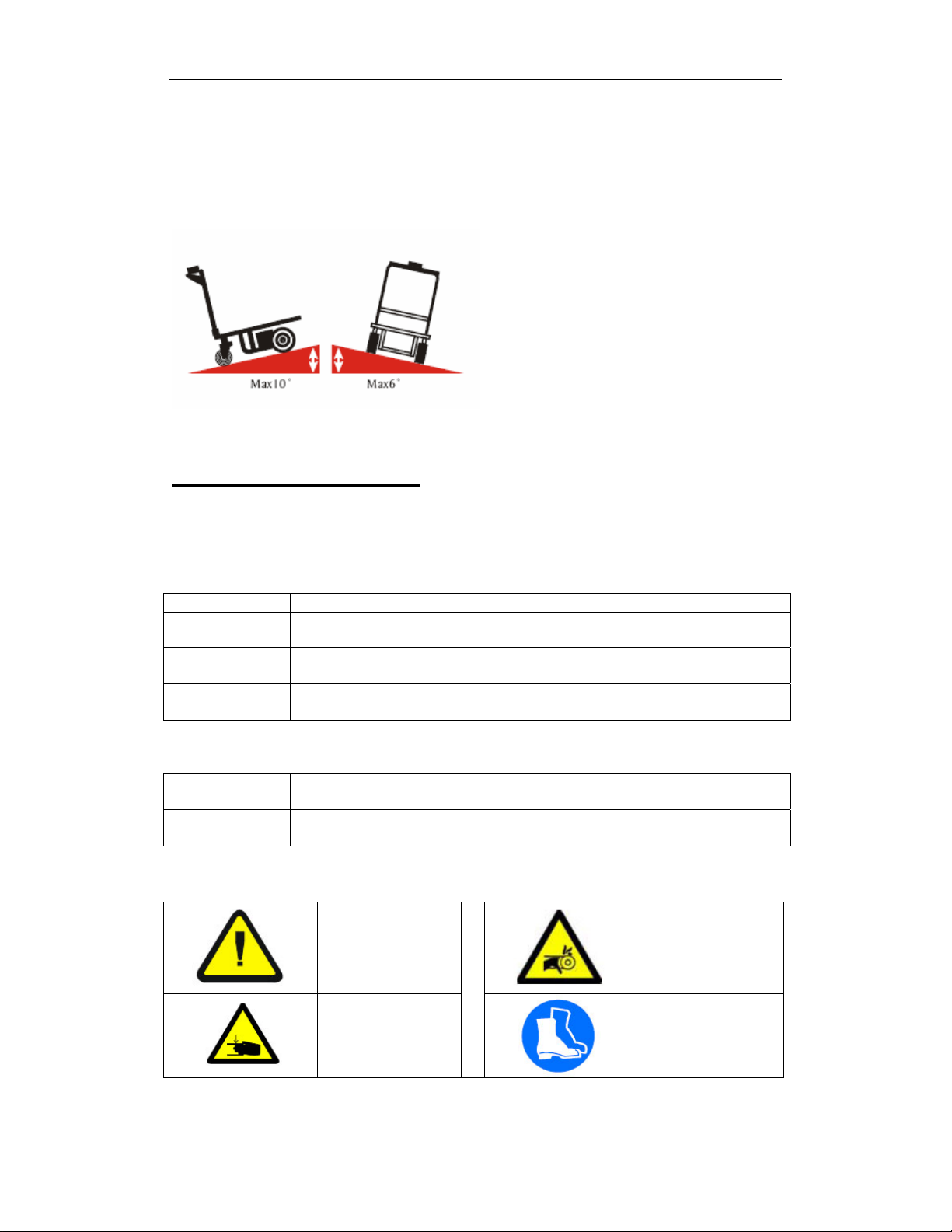
Warning: Any attempt to climb or descend an incline steeper than shown below may
put your E-CART in an unstable position and cause it to tip, resulting in personal injury.
SYMBOLS & PICTURES
In addition to the text and illustrations, this operating manual contains various symbols
which should draw attention to the safety requirements.
They generally have the following appearance:
Signal wording Explanation
DANGER
WARNING
CAUTION
Other definitions:
DIRECTION
IMPORTANT
USE SYMBOLS & PICTURES
Warning of an imminent danger!
Non-observance cause death or serious injury
Warning of a possibly incoming dangerous situation.
Non-observance may cause death or serious injury.
Warning of a possibly incoming dangerous situation.
May also be used for warnings of major damage to property.
Marks recommendations for use and other useful information.
Does not warn of dangerous situations.
Warns of a harmful situation.
Non-observance may cause damage to material.
Possible danger to file
and limb or machine!
Danger of crushing!
Do not reach into
running motor!
Wear safety shoes
8
Page 9
E-CART (ELECTRIC CART)
Product description
Designated use
The CART is to be used on hard level surfaces.
¾ To move the stacker between buildings, warehouses etc
The gradient of the slope must not be more than 10%
Make sure load is not loose or unstable.
Do not pick up loads on tips or forks or edge of platform.
Do not overload.
The road surfacing must be solid and have a good grip.
Travel routes must offer sufficient load-bearing capacity for the loaded CART.
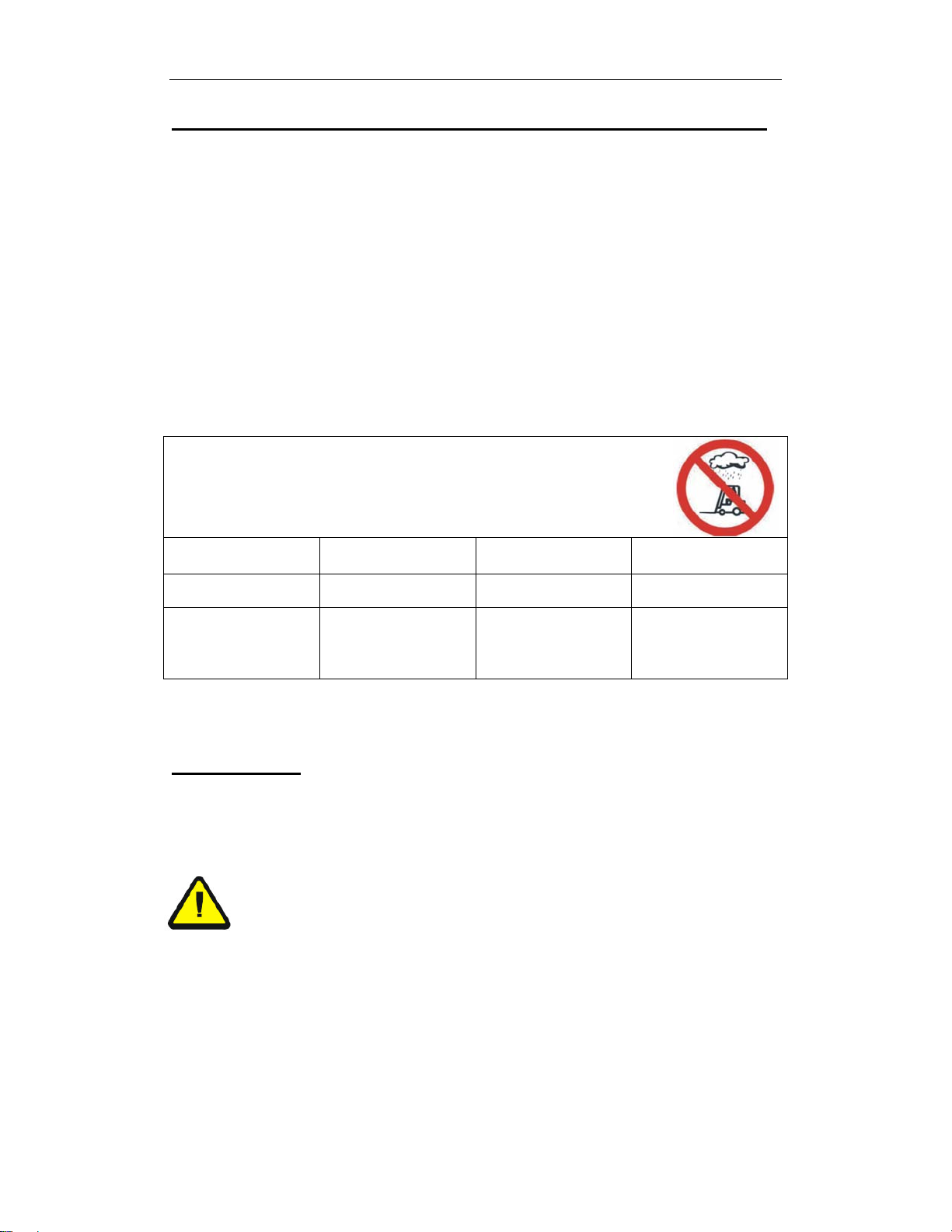
The CART is not suitable for continuous use in cool-houses!
Ambient conditions
Temperature From
To
14
113
°F
°F
Degree of humidity ≤70 %
Permitted floor
incline
y Loaded
y Unloaded ¹
Max. 0.5
Max. 2.0
%
%
OPERATION
Visually inspect E-CART for damaged and worn parts, before
Electric Cart is taken into operation.
read and understand all instructions
Caution!
Pedestrian controlled industrial trucks may only be operated by persons who
have been satisfactorily instructed in operating the truck and have proved their
ability to operate the truck to the responsible representative of the operating
company.
The first driving attempts should take place on level and spacious surfaces.
Recommendation:
The operator who is to maneuver the CART should be allowed to practice, when
unloaded, until they can safely operate these functions.
Authorized person should
9
Page 10
E-CART (ELECTRIC CART)
Travel
The butterfly switch controls the direction and speed of the lift truck.
Rotating the butterfly control towards the f o rks moves the truck in the forward
direction. Rotating the butterfly control away from the forks, moves the truck
in the reverse dir ection. The control is progre ssive – the further you rotate the
control, the faster the truck will travel.
DIRECTIONAL SPEED CONTROL THROTTLE
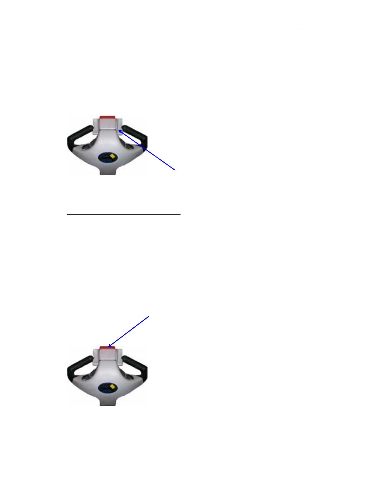
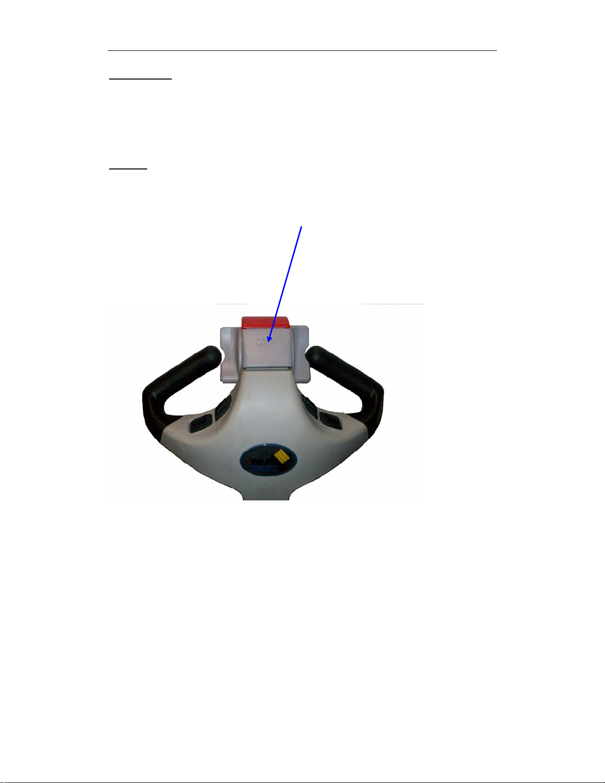
Emergency reverse safety button
At the top of the handle is a red safety reverse button. The button is
designed to change the travel direction away fro m the operator when depressed.
The truck will stop moving away from the operator when the button is re leased.
When the fork truck is traveling forward (away from the operator) the button
has no effect when activated.
If the belly switch becomes jammed or stuck, it will move forward (away
from the operator) for a maximum of 3 seconds at which time the control circuit
will become disabled until the handle is re-set to the full up or full down position
and the belly switch is returned to normal operation.
BELLY SWITCH (SAFETY REVERSE BUTTON)
10
Page 11
E-CART (ELECTRIC CART)
TO BRAKE
This cart is equipped with a brake that is applied between 1~5 degrees of the
vertical position . When you release your hand from the handle. It will resume
the neutral position automatically, as the brake in work. Always make sure that
the brake is in work before operating the cart .
HORN
A horn is located on the front side of the handle.
HORN
11
Page 12

E-CART (ELECTRIC CART)
Maintenance and repair
TROUBLESHOOTING GUIDE -- ______
Warning: Before performing any task, always block drive wheel off of the ground.
Consult the factory for problems at time of installation, or for any problems not addressed
below.
Problem: Possible cause(s): Action:
Unit doesn’t mov e wh en c on t r ols a r e
used.
Unit will not charge
Unit will not go forward; reverse
works; belly switch just kills unit
(does not go forward and time out)
Unit will not go reverse; belly switch
works (i.e. when the handle is in
operating range and rotating
throttle in reverse and the belly
switch is hit, the unit moves
forward and times out)
Battery voltage low (<17)
Problem with motor controller
(check for LED flash code on side
of controller)
Fuse blown
Charger malfunction
Bad batteries
Broken wire, or loose connection
Contactor bad, motor controller bad
Broken wire, or loose connection,
contactor bad, motor controller
bad
Charge batteries.
Consult diagnostics
page/factory
Remove back shroud and check
fuses (3 fuses).
Verify output voltage on charger,
will only get a reading when
connected to batteries; should be
approximately 28 volts.
Load test batteries
Locate Pin 2 on Molex connector at
motor controller. Trace wiring to
contactor and verify connection.
When forward is depressed, there
should be 24 volts on this wire
from Molex connector to the
contactor, if not, the motor
controller may be bad; consult
diagnostics page/factory. If 24
volts is present at contactor,
verify ground connection. If
ground is good, remove both wires
and check with ohm meter;
resistance should be
approximately 38 ohms. If it’s
open or zero, the contactor should
be replaced.
Same as above; except locate Pin 3
on Molex connector on motor
controller…and follow procedure.
12
Page 13

E-CART (ELECTRIC CART)
Problem: Possible cause(s): Action:
Unit will not go forward, or reverse,
but belly switch still functions
properly.
Unit will not move forward, or
reverse, and the Belly switch will
not function, unit does turn on as
indicated by the battery gage
lighting up.
Broken wire, or loose connection,
bad motor controller,
Throttle assembly bad
Blown fuse
Broken wire, or loose connection
Locate Pin 6 on Molex connector at
the motor controller. Try to drive
the unit in forward, there should
be 0 to 5 volts (5v is full throttle)
at this pin. If there is voltage and
the unit does not move, the motor
controller may be bad, consult
diagnostics page/factory. If
there is no voltage, trace the
wiring back towards the tiller head
and check voltage on each side of
connectors. Continue this until
bad connection is found.
If the connections are all good, and
there is no voltage coming out of
throttle assembly, then the
throttle assembly may be bad.
Verify there is 24 volts going into
the assembly and that there is a
good ground. If there is still no
output voltage for pin 6, replace
throttle assembly. See Fig. 1
Verify fuses are good, replace if
blown.
Locate Pin 7 on Molex connector at
the motor controller. Trace wire
back up to tiller head and verify
continuity all the way to the
throttle assembly. Repair any
loose connections.
If there is continuity up to the
throttle assembly, then check the
ground wire that comes off of B-
on the motor controller (3
rd
terminal down). Add more length
to this wire if necessary, and
re-terminate with a ring terminal.
13
Page 14

E-CART (ELECTRIC CART)
Unit will not go forward; the belly
switch functions; reverse works.
Unit will not reverse; belly switch
does not function; forward ok
Belly switch does not function;
forward ok; reverse ok
Broken wire, or loose connection,
bad motor controller
Bad throttle assembly
Broken wire, or loose connection,
bad motor controller
Bad throttle assembly
Broken wire, or loose connection,
bad motor controller
Bad belly switch
Locate Pin 11 on Molex connector at
the motor controller. Try to drive
the unit in forward; there should
be 24 volts at this pin. If there is
voltage and the unit does not
move, the motor controller may be
bad, consult diagnostics
page/factory. If there is no
voltage, trace th e wiring back
towards the tiller he ad and check
voltage on each side of
connectors. Continue this until
bad connection is found.
If the connections are all good, and
there is no voltage coming out of
throttle assembly, then the
throttle assembly may be bad.
Verify there is 24 volts going into
the assembly and that there is a
good ground. If there is still no
output voltage for pin 11, replace
throttle assembly. See Fig. 1
Locate Pin 12 on Molex connector at
the motor controller. Try to drive
the unit in reverse; there should
be 24 volts at this pin. If there is
voltage and the unit does not
move, the motor controller may be
bad, consult diagnostics
page/factory. If there is no
voltage, trace th e wiring back
towards the tiller head and check
voltage on each side of
connectors. Continue this until
bad connection is found.
If the connections are all good, and
there is no voltage coming out of
throttle assembly, then the
throttle assembly may be bad.
Verify there is 24 volts going into
the assembly and that there is a
good ground. If there is still no
output voltage for pin 12, replace
throttle assembly. See Fig. 1
Locate Pin 13 on Molex connector at
the motor controller. Try to drive
the unit in reverse, and hit the
belly switch… there should be 24
volts at this pin. If there is
voltage and the unit does not
move, the motor controller may be
bad, consult diagnostics
page/factory. If there is no
voltage, trace th e wiring back
towards the tiller he ad and check
voltage, or continuity on each side
of connectors. Continue this until
bad connection is found.
If the connections are all good, and
there is no voltage, then the
switch may be bad. Verify there
is 24 volts going into the switch.
14
Page 15

E-CART (ELECTRIC CART)
Unit will not reverse. The unit only
goes forward for about 1 second
and dies when the handle is pulled
down. When the handle is re-set
and pulled down the unit will move
forward again then die.
Unit will not reverse; belly switch
does not function; forward ok
Stuck Switch
Broken wire, or loose
connection, bad throttle
assembly, bad motor controller.
If there is still no output voltage
for pin 13, replace the switch.
The belly switch is stuck on.
Tap the orange assembly to see
if the switch can be freed. If
this doesn’t work, disassemble
the tiller head by removing 3
screws from bottom. Slightly
loosen up the two screws that
hold the switch in place, this
may free the switch. If it is still
stuck, contact the factory for a
replacement switch.
Locate Pin 12 on Molex
connector at the motor
controller. Try to drive the unit
in reverse; there should be 24
volts at this pin. If there is
voltage and the unit does not
move, the motor controller may
be bad, consult factory. If
there is no voltage, trace the
wiring back towards the tiller
head and check voltage on each
side of connectors. Continue
this until bad connection is
found. If the connections are
all good, and there is no voltage
coming out of throttle assembly,
then the throttle assembly may
be bad. Verify there is 24 volts
going into the assembly and that
there is a good ground. If there
is still no output voltage for pin
12, replace throttle assembly.
15
Page 16

E-CART (ELECTRIC CART)
Instructions for Changing the Batteries, estimated time, 15 min.
READ ALL INSTRUCTIONS BEFORE PROCEEDING!
Only qualified personnel should work on this equipment!
Lock out all potential energy sources before attempting this inst allation; turn off the un it
and remove the key.
Warning!
! Working with or near lead acid batteries is dangerous. Batteries contain sulfuric acid and
produce explosive gases. A battery explosion could result in loss of eyesight or serious burns.
! Do not smoke or allow a spark or flame near batteries. Charge batteries in locations which
are clean, dry, and well-ventilated. Do not lay tools or anything metallic on top of any battery.
All repairs to a battery must be made by experienced and qualified personnel.
! When working with batteries, remove personal items such as rings, bracelets, necklaces, and
watches. Batteries can produce enough energy to weld jewelry to metal, causing a severe burn.
! Always have fresh water and soap nearby in case battery acid contacts skin, clothing, or eyes.
! Operating the battery with a low battery voltage can cause premature motor contact failure.
! Do not expose the lift or charger to rain or adverse conditions.
! Replace defective cords or wires immediately.
! Check the battery’s water level frequently if this applies to your battery type.
! Make sure the battery charger is unplugged from 115vac source.
Battery Charger Operating Instructions
Plug the charger into a standard 115V receptacle. If an extension cord must be
used, keep it as short and as large as possible. A small cord will decrease the output
of the charger due to the voltage drop in the line. This will increase the charging time.
It can also cause the 115V cord to overheat.
When properly connected, the charge LED will indicate the status of charge current
flowing to the battery, as follows: Power LED is always green when charger is plugged in.
The status light is as follows:
Red only – the charger is providing full output to the battery.
Yellow – the charger is “topping off” the battery.
Green – the charger is providing a “float,” or maintenance, charge.
Remember to unplug the charger before moving the equipment. Failure to do so could cause damage to cords, receptacles
and other equipment.
16
Page 17

E-CART (ELECTRIC CART)
Troubleshooting:
If the unit does not operate, check all of the wiring connections to make sure they’re both
mechanically and electrically sound – specifically at the battery, and the motor.
A fully-charged lead acid battery in good cond ition at room temperature should read 12.65
volts. At 11.9 volts it is considered to be fully discharged and in ne ed of char gi ng. When checking
battery voltage, wait at least 1\2 hour after the charger has been turned off before checking the
battery’s voltage.
If the batteries aren’t being charged by the charger, check the output
charger fuse. Verify fuse is good with an ohmmeter, or close visual
(ohm meter best). Fuse is a 10Amp 250 Volt; GBD 10A. If it is good,
check the battery’s state of charge with a voltmeter. The charger must
be connected to the battery in order to read the output voltage of the
battery charger. Depending on the state of charge of the batteries, the
voltage should be somewhere around 27 to 28 volts dc.
If it is determined the batteries are dead, and need replaced, change the batteries.
Tools Required:
14mm wrench, or crescent wrench
Regular flat bladed screw driver
17
Page 18

E-CART (ELECTRIC CART)
Instructions; Changing the Motor Controller in; estimated time, 30 min.
READ ALL INSTRUCTIONS BEFORE PROCEEDING!
Only qualified personnel should work on this equipment!
Lock out all potential energy sources before attempting this inst allation; turn off the un it
and remove the key.
Warning!
! Working with or near lead acid batteries is dangerous. Batteries contain sulfuric acid and
produce explosive gases. A battery explosion could result in loss of eyesight or serious burns.
! Do not smoke or allow a spark or flame near batteries. Charge batteries in locations which
are clean, dry, and well-ventilated. Do not lay tools or anything metallic on top of any battery.
All repairs to a battery must be made by experienced and qualified personnel.
! When working with batteries, remove personal items such as rings, bracelets, necklaces, and
watches. Batteries can produce enough energy to weld jewelry to metal, causing a severe burn.
! Always have fresh water and soap nearby in case battery acid contacts skin, clothing, or eyes.
! Operating the battery with a low battery voltage can cause premature motor contact failure.
! Do not expose the lift or charger to rain or adverse conditions.
! Replace defective cords or wires immediately.
! Check the battery’s water level frequently if this applies to your battery type.
! Make sure the battery charger is unplugged from 115vac source.
Troubleshooting:
If it has been determined the motor controller needs to be replaced, the following procedure
can be used.
Tools Required:
2x 14mm wrench, open face
Philips head screwdriver
8mm wrench
18
Page 19

Filename: Belly Switch trouble shoot
This is the top side of the tiller. Fig1
E-CART (ELECTRIC CART)
Fig.1
This is the driver side of the tiller, looking at the belly switch. Fig 2
Fig.2
19
Page 20

E-CART (ELECTRIC CART)
Filename: Belly Switch trouble shoot
This is the bottom side of the tiller handle. 3 Allen head screws need to be removed. Fig.3
Fig.3
Lift the front top edge of the tiller cover u p. Fig4
Fig.4
20
Page 21

E-CART (ELECTRIC CART)
Filename: Belly Switch trouble shoot
Fig.5
Carefully pull the belly switch back off of the tiller while tipping the front up.
Fig 6
Fig.6
21
Page 22

E-CART (ELECTRIC CART)
Filename: Belly Switch trouble shoot
The tiller assembly cover should come off, just be careful not to drop it and rip out the wiring from
the connectors. At this point, the tiller throttle assembly can be replaced
with a new one by just unplugging the two connectors. Or, if the problem appears to be in the
belly switch itself, further breakdown of t he assembly can continue to search for the problem. Fig 7
Fig.7
Unplug the two connectors from the tiller throttle assembly. Fig8
Fig.8
22
Page 23

E-CART (ELECTRIC CART)
Filename: Belly Switch trouble shoot
Remove Philips screw on throttle. Fig.9
Fig.9
Throttle wheel will then pull off. Take note of the orientation of the wheel on the shaft. Correct
orientation is shown here. Fig 10
Fig.10
23
Page 24

E-CART (ELECTRIC CART)
Filename: Belly Switch trouble shoot
Do the same on the other side, taking note of th e orientation of the two plastic bushings. If the
throttle wheel had a tendency to stick , contact Vestil Manufacturing for replacement bushings. Fig
11
Fig.11
The front of the red cover should be connected via the gray nub. Fig 12
Fig.12
24
Page 25

E-CART (ELECTRIC CART)
Filename: Belly Switch trouble shoot
To remove the red cover, use a small scr ewdriv er and carefully lift the plastic up over the gray nub.
Fig 13
Fig.13
Do the same on the other side, and remove. Fig 14
Fig.14
25
Page 26

E-CART (ELECTRIC CART)
Filename: Belly Switch trouble shoot
This should expose a spring. This spring has a specific o rientation. When assembled the spring
sets in the red cup on the inside of the red belly cover. Fig 15
Fig.15
The other side of the spring fits over the gray plastic nub above the switch. Fig 16
Fig.16
26
Page 27

E-CART (ELECTRIC CART)
Filename: Belly Switch trouble shoot
Another picture of the nub, spring not shown. At this point, verify the solder joints are in tact and
the two wires are attached to the switch as shown below. Also verify the belly switch is not stuck
in. You should be able to push on the switch and the actuator will move freely in and out, you
should here a click as you do this. If the switch is stuck in contact Vestil Manufacturing for
replacement options. Fig17
Solder
connection
Belly Switch
actuator
Solder
connection
Fig.17
Replace any broken/missing components. To assemble, press the red belly switch cover back on
the tiller head seating the red holes over the gray nubs. Basically the opposite of the procedure in
Fig. 17, but without a screwdriver. Fig 18
Fig.18
27
Page 28

E-CART (ELECTRIC CART)
Filename: Belly Switch trouble shoot
The spring can be pushed into position.
Fig. 19
Fig.19
This is the spring shown not seated completely. Push the spring into the pocket, and over the gray
plastic nub. Fig20
Fig.20
28
Page 29

Install bushings. Fig21
E-CART (ELECTRIC CART)
Filename: Belly Switch trouble shoot
Fig.21
Put throttle thumb wheels back on. Fig22
Fig.22
29
Page 30

Install Philips screw. Fig23
E-CART (ELECTRIC CART)
Filename: Belly Switch trouble shoot
Fig.23
Re-installing the tiller cover is basically reversing steps Fig 3 thru 7; with the following
precautions/steps.
Make sure red tabs on each side goes on top of black nub s when inst alli ng tiller cov er on the ha ndle.
Fig 24
Red Tab on
each side
Fig.24
30
Page 31

E-CART (ELECTRIC CART)
Filename: Belly Switch trouble shoot
Black nub for right side shown here; and the next photo Fig 25
Fig.25
The red tab slides over the top of this black nub on each side when installing the tiller throttle
assembly back on the handle. Fig 26
Plastic Nub
Fig.26
31
Page 32

E-CART (ELECTRIC CART)
Filename: Belly Switch trouble shoot
This shows sliding the red tabs over the black nub. This is basically the reverse of Fig6.
Red tab
Black nub
Fig.27
This is the top front where the two connectors are. Make sure they are on each side of the stand off
so the wires do not get pinched. Fig28
Stand off
between
connectors
Fig.28
32
Page 33

E-CART (ELECTRIC CART)
Filename: Belly Switch trouble shoot
Gently push the tiller throttle assembly in place. Again, it’s just reversing steps 3 through 7 to get
the tiller throttle assembly back on the handle. Re-install the 3 Allen screws, verify no switches are
sticking, and that the thumb wheel moves freely. Turn the unit on and verify operation. This
completes the assembly.
5mm Allen
screws; 3
places
Fig.29
33
Page 34

E-CART (ELECTRIC CART)
Free Wheeling E-CART
If for reasons of convenience, you require to push your E-CART for a short distance, the
drive system can be put into ‘freewheels mode’. This will allow your E-CART to roll freely.
E-CART Freewheel Procedure
The freewheel device is a lever located at the front right hand side of your E-CART (Fig.1)
Fig.1
To freewheel E-CART first switch off the power switch located on control handle (Fig.2)
Old handle with Key switch assembly
New handle with ON/OFF switch
34
Page 35

E-CART (ELECTRIC CART)
push down
Pull up
Push down the lever until a distinct click is felt (disengage) Fig.3.
Fig.3
Push and maneuver E-CART manually with ease.
To re-engage the drive system, simply pull backwards on the lever until a distinct click is felt
(engage).
Turn the power switch “ON” on the control handle and you will be able to operate the
E-CART once again.
Warning: Always check that the freewheel device is in the drive position before attempting
to operate your E-CART after it has been left unattended for a period of time. Failure to
observe this warning may result in an accident.
35
Page 36

E-CART (ELECTRIC CART)
Maintenance and repair
(A) DAILY CHECK THE FOLLOWING:
1) Frayed wires
2) Damage or structural deformation to the structural members.
3) Unusual noise or binding, or evidence thereof.
4) Proper functioning of all limit switches, including those on the perimeter pinch point
guard (if applicable)
5) Horn works
6) Battery, keep the surface of battery clean and dry. Make sure battery is secured
against slipping. Make sure batteries are fully charged.
7) Tire condition.
(B) SIX MONTHS Check and adjust as necessary:
1) Tire wear, replace as necessary
2) All fasteners and fittings for sound function. Unusual noises or movement during
operation
3) Tension of handle bar lock and hinge bolt
4) Battery connections
5) Inspect all electrical plugs and sockets for damage and good contact and fit. Proper
water level in the battery
6) Proper functioning of any hand-or foot-operated mechanisms
7) All the information, safety, and wearing labels being in place and in good condition
8) The need to clean off dirt and debris
(C) ANNUALLY Check the following and adjust as necessary:
1) Tire bearings for wear
2) Handle bar bolts and nuts
3) Chassis for sounds
4) Drive wheel hub keys
5) All wheel bolts
6) Drive axle securing bolts
7) Motor mounting bolts
8) Magnetic motor brake disc and function
9) Main wiring harness for damage
10) Clean chassis and repaint any exposed parts
11) Lubricate ON/OFF power key barrel
12) Replace any damaged axle seals
13) Cycle test charger for full operation function
14) Cycle test batteries for operating capacity
15) Check motor brushes for any wear in the lift motor, & if necessary change motor
brushes.
16) Check the condition of your tires regularly. Look for sign of wears, cuts and foreign
objects lodged in the tread.
Note the items listed under weekly and six months should be incorporated into this
annual inspection.
Use a general purpose light lubricating oil on moving parts.
All wheel bearings are factory sealed and should not normally need lubrication.
36
Page 37

E-CART (ELECTRIC CART)
DRIVE TRANSMISSION LUBRICATION
This unit is factory filled and will not normally need additional lubrication.
Note: E-CART transmission is filled with a special lubricant. Don’t attempt to force
grease into the transmission as this will contaminate the original lubrication and will
invalidate your warranty.
37
Page 38

Serial No. __________________
Model: ____________________
LIMITED WARRANTY
Vestil Manufacturing Corporation (Vestil) warrants E-CART model Traction-Drive Carts, to be free of defects in
material and workmanship during the warranty period. Our warranty obligation is to provide a replacement for a
defective original part (a part that used to make the product as shipped to the warrantee) after we receive a
proper request for warranty service. “Proper request” means that we must receive: 1) a photocopy of the
Customer Invoice from Vestil (or authorized distributor) that displays the shipping date; AND 2) a written request
for warranty service. Send requests by any of the following methods:
Mail Fax Email
Vestil Manufacturing Corporation (260) 665-1339 sales@vestil.com
2999 North Wayne Street, PO Box 507
Angola, IN 46703
In the written request, list the parts you believe are defective and include the address where replacements
should be delivered. After Vestil receives your request, an authorized representative will contact you to
determine whether your claim is covered by the warranty (also see “What will Vestil do to correct defects”
below). Before providing warranty service, Vestil may require you to send the entire product or the defective
part or parts to its facility in Angola, IN.
Who may request service?
Only the warrantee may request service. You are a warrantee if you purchased the product from Vestil or from
an authorized distributor AND the product is fully paid for.
What is covered under the warranty?
The warranty covers the following original drive components: drive motors, electronic controllers, and switches.
It also covers original parts that wear under normal usage conditions (“wearing parts”): bearings, wheels, seals,
motor brushes, batteries, and the battery charger. The warranty period for drive and lift components is 1 year
For wearing parts, the warranty period is 90 days
. Both warranty periods begin on the date when Vestil ships
the product to the warrantee. If you purchased the product from an authorized distributor, the periods begin
when the distributor ships the product, which extends the warranty by up to an additional 30 d ays.
If a defective part is covered by the warranty, what will Vestil do to correct the problem?
Vestil will provide an appropriate replacement for any covered part. An authorized representative of Vestil will
contact you to discuss your claim and to arrange warranty service.
What is not
covered by the warranty?
1. Labor costs;
2. Any of the following automatically void the warranty:
• Product misuse;
• Negligent operation or repair;
• Corrosion or use in corrosive conditions;
• Inadequate or improper maintenance;
• Failure to exercise good judgment;
• Damage sustained during shipping;
• Accidents involving the product;
• Unauthorized modifications
: Do NOT modify the product IN ANY WAY without first receiving
written authorization from Vestil. Modifications may render the pallet truck or stacker unsafe
to use or might cause excessive and/or abnormal wear.
Do any other warranties apply to the ladder stand?
Vestil Manufacturing Corp. makes no other express warranties. Any warranty implied-by-law is limited in
duration to the warranty period.
.
 Loading...