

Page 1
INSTRUCTION MANUAL
MANUAL TRASH COMPACTOR
MTC MTC-RB
MODEL NO. ________________________
SERIAL NO. ________________________
VESTIL MANUFACTURING CORP.
2999 NORTH WAYNE STREET, P.O. BOX 507, ANGOLA, IN 46703
TELEPHONE: (260) 665-7586 -OR- TOLL FREE (800) 348-0868
FAX: (260) 665-1339
URL: WWW.VESTILMFG.COM EMAIL: SALES@VESTIL.COM
MTC 22-126-130 0909
Page 2

SAFETY PRINCIPLES
Each manual trash compactor conforms to the generalized specifications disclosed in this manual and
conforms to our demanding standards for quality, durability and user safety.
Vestil Manufacturing Corp. recognizes the critical importance of workplace safety. Each person who might
participate in the assembly, use, inspection or maintenance of the product must read this manual. Read the
entire manual and fully understand each instruction BEFORE assembling, using or maintaining the
compactor. If you do not understand an instruction, contact Vestil for clarification. Failure to adhere to
the directions in this manual might lead to serious personal injury or even death.
Vestil is not liable for any injury or property damage that occurs as a consequence of failing to apply the safe
operation and maintenance procedures explained in this manual or that appear on labels affixed to the product.
Failure to exercise good judgment and common sense may result in property damage, serious personal injury, or
death, and such failure is not the responsibility of Vestil.
This manual applies the hazard identification methods recommended for instruction manuals by the American
National Standards Institute (ANSI) in standard Z535.6-2006. In accordance with ANSI guidelines, this manual
identifies personal injury risks and situations that could lead to property damage with SIGNAL WORDS. These
signal words announce an associated safety message. The reader must understand that the signal word chosen
to identify a particular hazard conveys information about the seriousness of that hazard according to the following
convention:
Identifies a hazardous situation which, if not avoided, WILL result in DEATH or SERIOUS
INJURY. Use of this signal word is limited to the most extreme situations.
Identifies a hazardous situation which, if not avoided, COULD result in DEATH or
SERIOUS INJURY.
Indicates a hazardous situation which, if not avoided, COULD result in MINOR or
MODERATE injury.
Identifies practices not related to personal injury, such as operation that could damage the cart.
No safety alert symbol (equilateral triangle enclosing an exclamation point) accompanies this
signal word.
TABLE OF CONTENTS PAGE
SAFETY PRINCIPLES ………..……………………………………………………. 2
RODUCT INTRODUCTION …………….…………………………………………. 4
P
XPLODED PARTS DIAGRAM AND PARTS LIST ………………………………….. 5
E
ARDWARE LIST ………………………………………………………..………… 6
H
SSEMBLY INSTRUCTIONS ………………………………………………..……… 7 - 8
A
PERATION …………………………………………………………………..…... 9
O
NSPECTIONS & MAINTENANCE .…………………………………………….…… 10 - 11
I
TABLE OF FIGURES PAGE
FIG. 1:
FIG. 2:
FIG. 3:
FIG. 4:
FIG. 5:
FIG. 6:
FIG. 7:
FIG. 8:
FIG. 9:
FIG. 10:
FIG. 11:
FIG. 12: PRODUCT LABEL PLACEMENT …………………………………..
ASSEMBLY STEP 1 …………………………………………………. 7
ASSEMBLY STEP 2 …………………………………………………. 7
ASSEMBLY STEP 3 …………………………………………………. 7
ASSEMBLY STEP 4 …………………………………………………. 7
ASSEMBLY STEP 5 …………………………………………………. 8
ASSEMBLY STEP 6 …………………………………………………. 8
ASSEMBLY STEP 7 …………………………………………………. 8
ASSEMBLY STEP 8 ………………………………………………….
JACK DIRECTION LEVERS ……………………………….….………
HANDLE PLACEMENT ………………………………………………..
MOVING UNIT ………………………………………………………..
8
9
10
10
11
- 2 -
Page 3

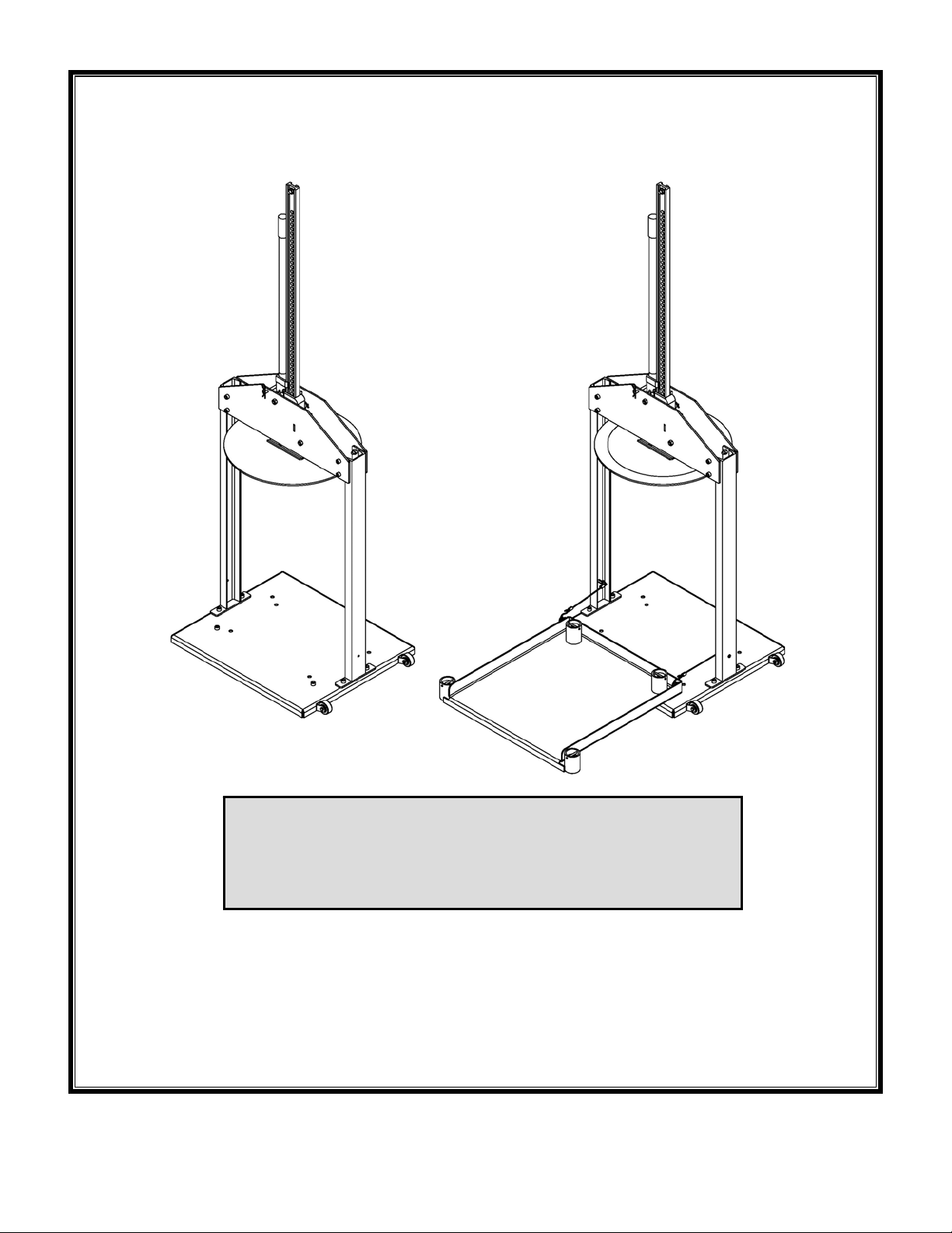
PRODUCT INTRODUCTION
To provide strength to compact a multiplicity of waste materials, each MTC is constructed
from steel components. A powder coat finish supplies protection from the elements. The
manually-operated jack produces 7,000 pounds of compacting force, which allows the operator
to reduce the size of waste material and thereby optimize space usage in waste storage
drums. Additionally, all 3 designs integrate wheels on one side of the base plate to allow an
operator to easily reposition the unit. Each compactor has a handle storage pin to prevent the
handle from pivoting downwards and potentially inflicting injuries while the compactor is in
storage.
The tabulated data below summarizes standard and optional features:
MODEL
MTC-30
MTC-55
MTC-RB
Thank you for purchasing a Manual Trash Compactor (MTC) made
by Vestil Manufacturing Corporation (“Vestil”). Our compactors are
rigorously engineered to produce durable, high-quality products.
Despite the compactor’s relatively simple mechanisms, all personnel
must familiarize themselves with the safe operation instructions
provided in this manual.
Maximum Rated
(W x L x H)
50in. X 24 1/4in. X 86in. 7000 155
(127cm x 62cm x 219cm) ~3182kg ~70kg
50in. X 24 1/4in. X 86in. 7000 163
(127cm x 62cm x 219cm) ~3182kg ~74kg
50in. X 46 9/16in. X 86in. 7000 231
(127cm x 119cm x 219cm) ~3182kg ~105kg
Load
Net Weight
(approx.) Dimensions
OPTIONS
ROLL OUT BASE
(FOR MTC-30 & 55)
55 GAL.
COMPACTOR
HEAD (Ø54cm x .64cm) ~12kg
COMPACTOR HEAD
29 1/4in. X 26 3/8in. X 4 13/16in. 800 53
(75cm x 67cm x 13cm) ~364kg ~24kg
Ø21in. X 1/4in. N/A 25
Ø17in. X 1/4in. N/A 16 30 GAL.
(Ø43cm x .64cm) ~8kg
Vestil Manufacturing Corp. created this manual to acquaint owners and users of the
compactor with safe use and maintenance practices. Employers are responsible for
instructing employees to use the product properly. Employees and all other persons,
who might foreseeably assemble, use, install, or perform maintenance on the
compactor, must read and understand every instruction before using it. Furthermore,
persons who use the compactor should have access to the manual at all times, and in
particular should read the directions before each use. Contact Vestil for answers to any
question(s) you have after reading the entire manual.
Although we strive to identify the foreseeable hazardous situations that might arise during
use, this manual cannot address every conceivable danger. The end-user must exercise
sound judgment while operating the compactor.
- 4 -
Page 4

Exploded Parts Diagram & Parts List
PARTS LIST
ITEM NO. DESCRIPTION QTY.
1 BASE WELDMENT 1
2 WHEEL, Ø2" X 7/8" X 1/4" BORED RUBBER 2
3 NYLOCK NUT, Ø1/4-20 UNC Z-PLATED 2
4 BOLT, HHCS #2 Z PLATED, Ø1/4 - 20 UNC x 1 1/2" LG 2
5 VERTICAL SUPPORT WELDMENT 2
6 BRACKET, FRONT JACK SUPPORT 1
7 JACK ASSEMBLY 1
8 BRACKET, BACK JACK SUPPORT 1
9 JACK CENTER SUPPORT 1
10 JACK SPACER (15/16” LONG) 2
11 PIN, CLEVIS 1
12 #7 HITCH PIN CLIP 1
13 COMPACTOR PLATE 1
14 BOLT, SHCS - 7/16-14 x 1 1/4" 14
15 BOLT, SHCS - 7/16-14 x 4 1/2" 2
16 NYLOCK NUT Z PLATED, Ø7/16 - 14 UNC 19
17 BOLT, CARRIAGE 7/16-14UNC x 1" LG. ZINC 3
18 JACK SPACER (3 ½” LONG) 1
MTC-RB ONLY BELOW, IN ADDITION TO ABOVE
15 BOLT, SHCS - 7/16-14 x 4 1/2" 1
16 NYLOCK NUT Z PLATED, Ø7/16 - 14 UNC 1
19 TRAY ASSEMBLY 1
20 BOLT, SHCS - Ø1/4-20 UNC X 3/4” 2
21 LOCK WASHER, Ø 1/4" 2
- 5 -
Page 5

- 6 -
Page 6

ASSEMBLY INSTRUCTIONS:
The numbers in parentheses correspond to item numbers from the “Parts List” on p. 5.
Fasten wheels (#2) in the brackets using ¼-20 x 1 ½” bolts (#4) and ¼-20 nylock nuts (#3). Bolt the
Step 1
vertical supports (#5) onto the base (#1) using 7/16-14 x 1 ¼” bolts (#14) and 7/16-14 nylock nuts (#16)
(Fig. 1).
Fig. 1: Assembly Step 1
As shown in Fig. 2, fasten the front jack plate (#6) onto vertical supports (#5) using #14 bolts and #16
Step 2
nylock nuts. Labels must face outward to be visible to operators.
Fig. 2: Assembly Step 2
Fig. 4: Assembly Step 4 Fig. 3: Assembly Step 3
Lay the partially assembled unit on its side as depicted in Fig. 3, and then insert #15 bolts through the
Step 3
holes in the jack plate. Slide a short jack spacer (#10) over the top bolt. Press the jack center support
(#9) into the appropriate slot.
Step 4 [NOTE: Press the handle against the jack mast in order to properly connect the jack to the frame.] Guide
the installed #15 bolts through the corresponding openings in the jack, as shown in Fig. 4; then slide the
remaining #10 spacer onto the top bolt and the long jack spacer (#18) onto the other bolt. If correctly
installed, the top bolt will project through the holes in the jack handle as well as the holes in the upper
jack slide as shown in the enlarged view in Fig. 4.
- 7 -
Page 7

A
Fasten the back jack plate (#8) onto the vertical supports (#5)
Step 5
using #14 bolts and 7/16-14 nylock nuts (Fig. 5). Make sure jack
center support (#9) aligns with the slot on back jack plate. Twist #16
nylock nuts onto the ends of the #15 bolts to secure the jack in place.
Connect the compactor plate (#13) to the end of the jack with
Step 6
the carriage bolts (#17) along with 7/16-14 nylock nuts with
warning labels facing the jack (Fig. 6). Place 7/16-14 x 1 ¼”
bolts into correct holes for drum stop (Fig. 7). The inside holes
are for 30 gallon drums, and the outside holes are for 55gallon
drums.
Fig. 6: Assembly Step 6
Store the compactor with the handle in an upright position. To secure
Step 7
the handle, insert the clevis pin (#11) into hole when unit is not in use.
Lock the pin in place with the hitch pin clip (F#12) (Fig. 7).
MTC-RB ONLY: Place Ø 1/4 - 20 UNC X 3/4
Step 8
bolts and 1/4in. lock washers through vertical
support holes (Fig. 8).
MTC-RB ONLY: Insert #15 bolt through the
Step 9
bottom hole on either vertical support weldment,
and through the hole on the roll-out tray when
moving unit (Fig. 8).
Fig. 8: Assembly Step 8
Fig. 5: Assembly Step 5
Fig. 7:
ssembly Step 7
- 8 -
Page 8

OPERATION:
Read the entire manual before you use the compactor for the first time AND before each subsequent use.
If questions remain after you finish reading the manual, contact Vestil for answers. DO NOT attempt to resolve
problems with the compactor UNLESS you are certain
that the device will be safe to use afterwards.
Improper operation may result in serious personal injuries.
• DO NOT compact contents into a container that is structurally insufficient/compromised.
• ALWAYS inspect the compactor and the waste drum BEFORE each use according to the inspection
instructions on p. 9. ONLY use the compactor if it passes the inspection.
• Waste storage drum may be too heavy for one person to maneuver. If necessary, ask someone to help you or
employ additional means to move the drum.
• NEVER modify or alter the compactor in any way without express, written authorization from Vestil.
Modifications and/or alterations might cause the compactor to function unpredictably, or might make the
compactor unsafe to use.
TO COMPACT WASTE MATERIAL:
Step 1
Free the jack handle by removing the storage pin (#11) (Fig.
7). Turn the jack direction levers to the “UP” position (Fig. 9),
and fully raise the compactor plate. MTC-RB units: remove
bolt securing roll-out tray (Fig. 8).
Step 2
Center drum under the jack. For MTC-RB units: roll out tray,
place drum on tray and push drum and tray under jack. Center
drum under jack.
Step 3 Turn the jack direction levers to the “DOWN” position (Fig. 9).
Keep fingers and hands away from compacting head while in use.
Stand to one side of the jack handle, so that your arms form a right angle with the handle, and ratchet the
Step 4
jack downward by moving the handle up and down. Be sure to fully raise and fully lower the handle,
which is necessary for the jack mechanisms to properly interact.
ratcheting. The handle my swing upwards if the handle is not pressed all the way down during ratcheting.
DO NOT stand directly behind (in line with) the handle or lean over the handle during
After the compactor plate contacts the waste material, continue ratcheting the jack until the desired
Step 5
degree of compaction is achieved. [NOTE: To optimally compress waste materials, use the compactor
frequently.]
Once compaction is complete, turn both direction levers to the “UP” position (Fig. 9).
Step 6
Ratchet the jack until the compactor plate is high enough to remove drum or until the compactor plate
Step 7
reaches the fully raised position.
Put the jack handle in the storage position with the clevis pin (#11). Secure the clevis with the hitch pin
Step 8
(#12) (Fig. 7).
Remove the waste storage drum. If you have the MTC-RB model, roll out the tray, remove drum and
Step 9
push back onto the base weldment. MTC-RB model only: Lock the tray assembly in the storage position
with a #15 bolt and #16 nylock nut (Fig. 8).
Step 10 Store the compactor in a safe location that offers protection from the elements.
Jack movement direction:
Down Up
FIG. 9: Jack Direction Levers
- 9 -
Page 9

TO MOVE THE COMPACTOR:
Failure to apply proper repositioning practices described in this section of the manual may result in
serious personal injuries.
• DO NOT move the compactor with a drum on the base weldment.
• Make sure that the jack handle is locked in the storage position with the clevis pin (#11) secured with the hitch
pin (#7).
• MTC-RB model compactors should only be moved with the roll-out tray secured according to Step 9 on p.8.
Stand to the side of the unit with the wheels, grab the jack and jack
Step 1
handle (Fig. 10).
Tilt the unit back until the
Step 2
wheels contact the ground (Fig.
11).
Push the unit to desired
Step 3
location, and then slowly lower
the raised side of the unit until
the base contacts the ground.
Fig. 11 MovingUnit
Fig. 10 Hand Placement
MAINTENANCE AND INSPECTIONS:
The end-user bears responsibility to verify that the compactor complies with all regulations, codes, and standards
that apply in the location where the device is used.
Inspections:
DO NOT use the compactor if an inspection reveals any structural damage. Structural damage
might include, but is not limited to, cracked welds, warping or other deformation of the frame members.
Regular/Frequent
before the compactor is used for the first time, and before each subsequent use. If the compactor is
infrequently used, conduct the following 2 steps at least once every 2 weeks. Inspect the compactor for:
1. Structural damage or deformation;
2. Proper functioning of the jack.
Periodic
rough operation:
Maintenance:
and safety of the compactor, and is responsible for training employees to work on the compactor. “Work on”
refers to operating, loading, cleaning, servicing, maintaining, or repairing the unit. ONLY trained, competent
maintenance personnel or contractors should perform inspection, maintenance, or repair work.
Step 1
Step 2
: inspect the following at least once per month for corrosion, damage, and excessive wear, or for noisy or
1. Compactor plate;
2. Jack front and back plates;
3. Jack and jack handle;
4. Fasteners (bolts, nuts, clevis pin and hitch pin);
5. Labels (as shown in Fig. 13, p. 11).
Tag the compactor, “Out of Service.”
Conduct “Regular/Frequent” and “Periodic” inspections.
: The person(s) designated to conduct inspections by your employer/the owner must do so
The owner/your employer must implement a maintenance program to ensure the proper function
- 10 -
Page 10

Step 3
Step 4
repairs, and modifications.
as tightening loose fasteners, or removing dirt or other debris from the surface of the compactor; a repair refers to
replacing worn parts with new replacement parts.
ONLY after finishing all necessary repairs and adjustments.
members or removing part(s). NEVER modify the compactor without the express, written approval of Vestil.
Modifications may render the compactor unsafe to use. If Vestil approves a modification in writing, you are
responsible for labeling the equipment with the following information:
Step 5
Step 6
If deformity, corrosion, rusting, or excessive wear of structural members is present, DO NOT use the
compactor. Contact Vestil for instructions.
Perform all other necessary adjustments and/or repairs.
The reader should understand the significant difference between necessary adjustments and
¾ An adjustment refers to a simple correction that restores the compactor to normal operating condition, such
¾ DO NOT use the compactor if adjustments and/or repairs are incomplete! Return the compactor to service
¾ A modification is a change that alters the compactor from its original condition, like bending the structural
1. Name of the person(s) who performed the modifications;
2. Date modification(s) performed;
3. Description of modification(s).
Contact Vestil for directions if a condition(s) are discovered during an inspection that is/are not addressed
in this manual.
Make a dated record of the repairs, adjustments and/or replacem ents made.
MARKINGS:
Only use the compactor if ALL labels are readable and undamaged. Contact Vestil for repl acement labels.
Fig. 12 Label Placement
- 11 -
 Loading...