

Page 1
Rev. 5/19/2017 MTC, MANUAL
Vestil Manufacturing Co.
2999 North Wayne Street, P.O. Box 507, Angola, IN 46703
Telephone: (260) 665-7586 -or- Toll Free (800) 348-0868
Fax: (260) 665-1339
Website: www.vestilmfg.com e-mail: info@vestil.com
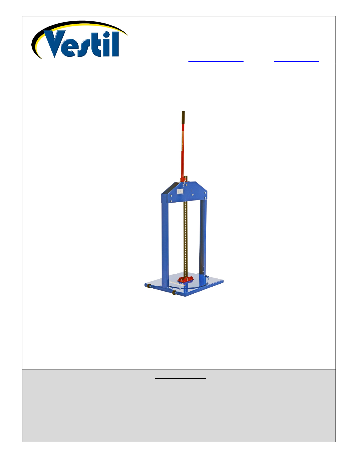
MTC-Series Manual Trash Compactors
Instruction Manual
RECEIVING INSTRUCTIONS:
After delivery, IMMEDIATELY remove the packaging from the product. Inspect the product closely to determine whether
it sustained damage during transport. If damage is discovered, record a complete description of it on the bill of lading and
notify the freight carrier. If the product is undamaged, discard the packaging.
NOTE:
The end-user is solely responsible for confirming that product design, installation, use, and maintenance
comply with laws, regulations, codes, and mandatory standards applied where the product is used.
Signal words……………………………………………………..…………………………………………………………… 2
Specifications………………………………..…………………….….……………………………………………………… 2 – 3
Exploded parts diagram and bill of materials………………….……………………………………………….…………. 4
Assembly instructions……………………………………………………………………………………………….. ……… 6
Operation instructions……………..………………………………………………………………………………………… 6
Moving the compactor …………..
Inspections & Maintenance………………………………………………………………………………………………… 7 - 8
Label Placement Diagram……...…………………………………………………………………………………………… 8
Limited Warranty…...………………………………………………………………………………………………………… 9
Copyright 2017 Vestil Manufacturing Co. Page 1 of 9
…………………………………………………………............................................. 7
Table of Contents
Page 2
Rev. 5/19/2017 MTC, MANUAL
SIGNAL WORDS:
This manual uses SIGNAL WORDS to indicate the likelihood of personal injuries, as well as the probable
seriousness of those injuries, if the product is misused in the ways described. Other signal words call attention to uses
of the product likely cause property damage. The signal words used appear below along with the meaning of each
word:
Identifies a hazardous situation which, if not avoided, WILL result in DEATH or SERIOUS
INJURY. Use of this signal word is limited to the most extreme situations.
Identifies a hazardous situation which, if not avoided, COULD result in DEATH or SERIOUS
INJURY.
Indicates a hazardous situation which, if not avoided, COULD result in MINOR or
MODERATE injury.
Identifies practices likely to result in product/property damage, such as operation that
might damage the product.
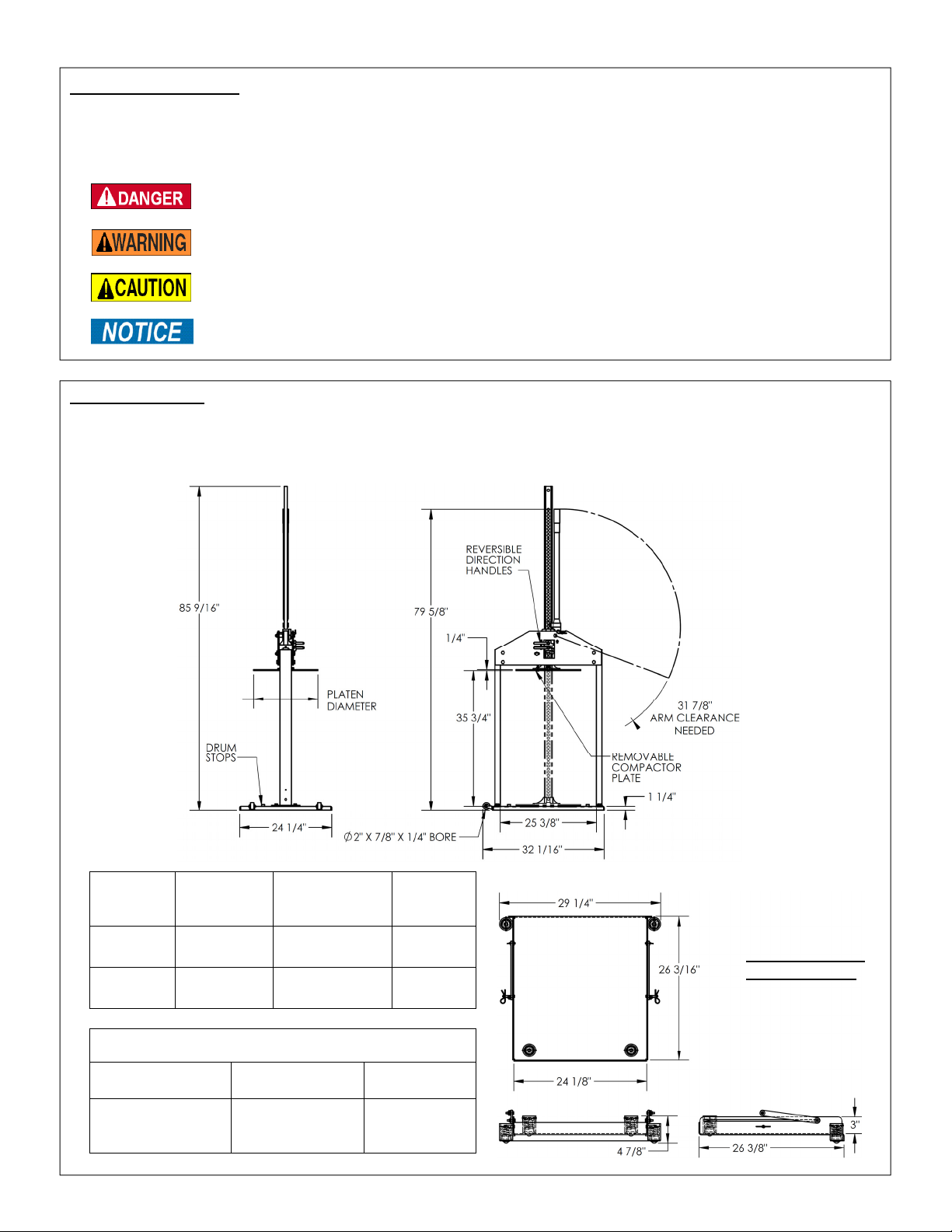
Specifications:
The jack produces 7,000 pounds of compacting force, which allows the operator to reduce the size of waste
material and optimize space in waste storage drums. Both MTC models include wheels on one side of the base plate
to allow an operator to easily reposition the unit. Each compactor has a handle storage pin to secure the handle while
it is not in use. Dimensions and other important specifications appear in the tables below.
Maximum
Compacting
Force
Capacity
800 lb.
~364kg
Net
Weight
Optional Roll-Out
Base (MTC-RB)
Net Weight
58 lb.
26.1 kg
Model
MTC-30
MTC-55
Model
MTC-RB
(ROLL OUT
BASE)
Platen
Diameter
17” 7000 lb. 158 lb.
43.2 cm ~3182 kg 71.7 kg
21” 7000 lb. 166 lb.
53.3 cm ~3182 kg 75.5 kg
Optional Equipment
Roll-Out Load
Copyright 2017 Vestil Manufacturing Co. Page 2 of 9
Page 3
Rev. 5/19/2017 MTC, MANUAL
1
5
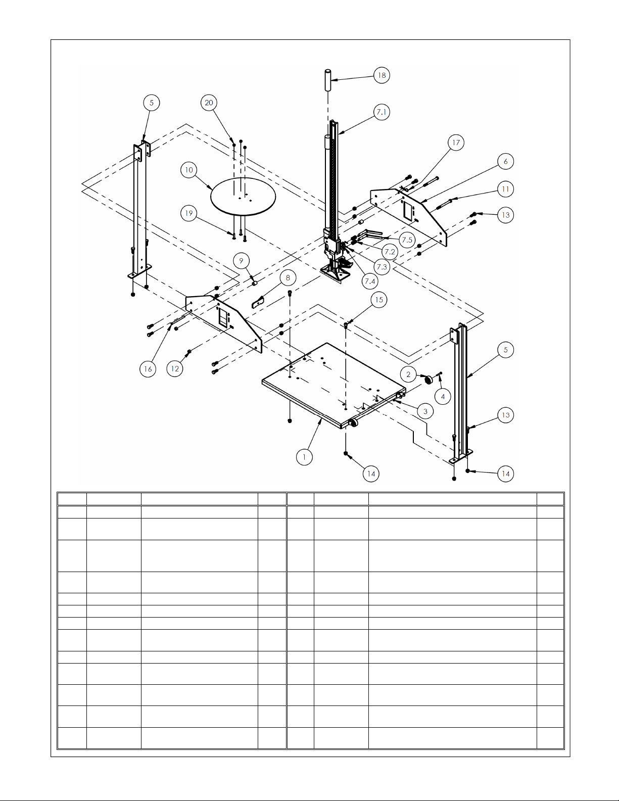
MTC-30 Exploded Parts Diagram & Bill of Materials
Item Part no. Description Qty. Item Part no. Description Qty.
1 22-514-018 Weldment, base 1 8 22-016-029 Jack center support 1
2 16-132-225
3 37018
4 11009
5 22-514-019 Weldment, vertical support 2 12 40171 M12-1.75 Nylock nut 2
6 22-016-024 Bracket, front jack support 2 13 11207 Bolt, HHCS #2, zinc plated, 1/2”-13x11/4” 12
7 22-543-001 Jack assembly 1 14 37030 1/2”-13 Nylon insert lock nut 14
7.1 22-043-001 Farm jack 1 15 93405
7.2 22-146-003 Spring, compression 2 16 99-112-006 Pin, clevis 1
7.3 64133
7.4 33088
7.5 22-612-003 Weldment, pin with handle 2 19 21259
20 37021
Copyright 2017 Vestil Manufacturing Co. Page 3 of 9
2” x 7/8” x 1/4” bore rubber
wheel
1
/4” – 20 UNC zinc-plated
Nylock nut
/4” – 20 UNC x 11/2” #2
HHCS zinc-plated bolt
Spring pin, plain finish,
3
/16”x1”
Washer, carbon steel, zinc
9
finish,
/16”
2 9 22-113-004 Spacer, jack
Compactor plate:
2 10 22-014-049
22-014-050
2 11 0154014
2 17 45286 #1 hitch pin clip,
2 18 07-025-005
MTC-30 (16 lb.; 17” diameter x 1/4” thick)
MTC-55 (25 lb.; 21” diameter x 1/4” thick)
Hex cap screw, zinc plated, M12-1.75
x120
Socket head cap screw, zinc plated, 1/2”13x1”
Handle grip, black rubber, 6” 1
Bolt, carriage, gr. A, zinc finish,
18UNC x 11/2”
Nylon insert lock nut, gr. 2, zinc finish,
5
/16”-18
1
/8” x 25/8” 1
/16”-
2
1
1
2
2
3
3
Page 4

Rev. 5/19/2017 MTC, MANUAL
Fig. 1:
Assembly Step 1
Fig. 2:
Assembly Step 2
Fig. 3:
Assembly Step 3
Fig. 4:
Ass
embly Step 4
Assembly Instructions:
The numbers in parentheses correspond to item numbers in the Parts List table on p. 3.
Step 1: Fasten wheels (2) to their brackets using ¼-20 x 1 ½” bolts (4) and ¼-20 nylock nuts (3). Bolt the vertical
supports (5) onto the base (1) using 7/16-14 x 1 ¼” bolts (14) and 7/16-14 nylock nuts (16). (See Fig. 1
below.)
Step 2: As shown in Fig. 2, fasten the front jack plate (6) onto vertical supports (5) using bolts (14) and nylock
nuts (16). Labels must face outwardly to be visible to users.
Step 3: Lay the partially assembled unit on its side as depicted in Fig. 3, and then insert bolts (15) through the
Step 4: [NOTE: Press the handle against the jack mast in order to properly connect the jack to the frame.] Guide
Copyright 2017 Vestil Manufacturing Co. Page 4 of 9
holes in the jack plate. Slide a short jack spacer (10) over the top bolt. Press the jack center support (9)
into the appropriate slot.
the installed bolts (15) through the corresponding openings in the jack, as shown in Fig. 4; then slide the
remaining spacer (10) onto the top bolt and the long jack spacer (18) onto the other bolt. If correctly
installed, the top bolt will project through the holes in the jack handle as well as the holes in the upper
jack slide as shown in the enlarged view in Fig. 4.
Page 5

Rev. 5/19/2017 MTC, MANUAL
Fig. 7:
Assembly Step 7
Fig. 6:
Assembly Step 6
Fig. 8
: Assembly Step 8
Step 5: Fasten the back jack plate (8) onto the vertical supports (5)
using #14 bolts and 7/16-14 nylock nuts (Fig. 5). Make sure
jack center support (9) aligns with the slot on back jack plate.
Twist nylock nuts (16) onto the ends of the bolts to secure the
jack in place.
Step 6: Connect the compactor plate (13) to the end of the jack with
the carriage bolts (17) along with 7/16-14 nylock nuts with
warning labels facing the jack (Fig. 6). Place 7/16-14 x 1 ¼”
bolts into correct holes for drum stop (Fig. 7). The inside
holes are for 30 gallon drums and the outside holes are for 55
gallon drums.
Step 7: Store the compactor with the handle in an upright position. To secure
the handle, insert the clevis pin (11) into hole when unit is not in use.
Lock the pin in place with the hitch pin clip (12). (See Fig. 7.)
Step 8: MTC-RB ONLY: Place Ø 1/4 - 20 UNC X 3/4
bolts and 1/4in. lock washers through vertical
support holes (Fig. 8).
Step 9: MTC-RB ONLY: Insert #15 bolt through the
bottom hole on either vertical support
weldment, and through the hole on the roll-out
tray when moving unit (Fig. 8).
Fig. 5: Assembly Step 5
Copyright 2017 Vestil Manufacturing Co. Page 5 of 9
Page 6

Rev. 5/19/2017 MTC, MANUAL
Operation instructions:
Read the entire manual before you use the compactor for the first time AND before each subsequent use.
If questions remain after you finish reading the manual, contact Vestil for answers. DO NOT attempt to resolve
problems with the compactor UNLESS you are certain that it will be safe to use afterwards.
Improper operation may result in serious personal injuries.
DO NOT compact contents into a container that is structurally insufficient/compromised.
ALWAYS inspect the compactor and the waste drum BEFORE each use according to the inspection
instructions on p. 9. ONLY use the compactor if it passes the inspection.
Waste storage drum may be too heavy for one person to maneuver. If necessary, ask someone to help you or
employ additional means to move the drum.
NEVER modify or alter the compactor in any way without express, written authorization from Vestil.
Modifications and/or alterations might cause the compactor to function unpredictably, or might make the
compactor unsafe to use.
Keep fingers and hands away from compacting head while in use.
DO NOT stand directly behind (in line with) the handle or lean over the handle during ratcheting. The handle my
swing upwards if the handle is not pressed all the way down during ratcheting.
Step 1: Free the jack handle by removing the storage pin (11) (Fig.
7). Turn the jack direction levers to the “UP” position (Fig. 9),
and fully raise the compactor plate. MTC-RB units: remove
the bolt securing the roll-out tray (see Fig. 8 on p. 5).
Step 2: Center drum under the jack. For MTC-RB units: roll out tray,
place drum on tray and push drum and tray under jack.
Center drum under jack.
Step 3: Turn the jack direction levers to the “DOWN” position (Fig. 9).
Step 4: Stand to one side of the jack handle, so that your arms form a right angle with the handle, and ratchet the
jack downward by moving the handle up and down. Be sure to fully raise and fully lower the handle,
which is necessary for the jack mechanisms to properly interact.
Step 5: After the compactor plate contacts the waste material, continue ratcheting the jack until the desired
degree of compaction is achieved. [NOTE: To optimally compress waste materials, use the compactor
frequently.]
Step 6: Once compaction is complete, turn both direction levers to the “UP” position (Fig. 9).
Step 7: Raise the jack until the compactor plate is high enough to remove the drum or until the compactor plate
reaches the fully raised position.
Step 8: Put the jack handle in the storage position with the clevis pin (11). Secure the clevis with the hitch pin
(12) (see Fig. 7 on p. 5).
Step 9: Remove the waste storage drum. If you have the MTC-RB model, roll out the tray, remove drum and
push back onto the base weldment. MTC-RB model only: Lock the tray assembly in the storage position
with a bolt (15) and nylock nut (16). (See Fig. 8 on p. 5.)
Step 10: Store the compactor in a location that offers protection from the elements. Keep the device dry at all
times.
Jack movement direction:
Down Up
FIG. 9: Jack Direction Levers
Copyright 2017 Vestil Manufacturing Co. Page 6 of 9
Page 7

Rev. 5/19/2017 MTC, MANUAL
Moving the Compactor:
Carelessness while moving the compactor might result in personal injuries.
DO NOT move the compactor while loaded with a drum.
Before moving the compactor, secure the jack handle in the storage position with clevis pin (11) & hitch pin (7).
[Units with option MTC-RB] Secure the roll-out tray as described in Step 9 on p.6 before moving the unit.
Step 1: Stand to the side of the unit where the wheels are mounted;
then grab the jack and jack handle. (See Fig. 10.)
Step 2: Tilt the unit towards you until the wheels contact the ground
(Fig. 10).
Step 3: Push the compactor to desired location. Then, slowly lower
the raised side of the unit until the base rests on the ground.
Fig. 10 Moving Unit
wheel
Maintenance and Inspections:
Regular maintenance is essential to keep the compactor in normal operating condition. DO NOT use the compactor if
structural damage is discovered during an inspection. Structural damage includes, but is not limited to, cracked welds,
warping or other deformation of the frame members.
Inspections:
Regular/Frequent: before using it for the first time and before each subsequent use, examine the jack for:
1. Structural damage/deformation;
2. Abnormal function: ratchet the compactor plate up and down
Periodic: Inspect the following components at least once per month for corrosion, damage, and excessive wear,
noisy or rough operation:
1. Compactor plate;
2. Jack front and back plates;
3. Jack and jack handle;
4. Fasteners (bolts, nuts, clevis pin and hitch pin);
5. Labels (as shown on p. 8).
Maintenance:
Implement a maintenance program to ensure that the compactor remains in normal operating condition.
Step 1: Tag the compactor, “Out of Service.”
Step 2: Conduct “Regular/Frequent” and “Periodic” inspections.
Step 3: If deformity, corrosion, rusting, or excessive wear of structural members is present, DO NOT use the
Step 4: Perform all other necessary adjustments and/or repairs.
compactor. Contact Vestil for instructions.
Perform all necessary adjustments and repairs but DO NOT modify the compactor. DO NOT
use the compactor if adjustments and/or repairs are incomplete! Return the compactor to service ONLY after
finishing all necessary repairs and adjustments.
Adjustments are simple corrections that restore the compactor to normal operating condition, such as
tightening loose fasteners or removing dirt or other debris from the surface of the compactor.
“Repairs” are processes that restore the compactor to normal operating condition, e.g. replacing worn or
damaged parts.
A modification is a change that alters the compactor from its original condition, like bending the structural
members or removing part(s). DO NOT modify the compactor without the express, written approval of Vestil.
Modifications may render the compactor unsafe to use. If Vestil approves a modification in writing, you are
responsible for labeling the equipment with the following information:
1. Name of the person(s) who performed the modifications;
2. Date modifications performed;
3. Description of modification(s).
Step 5: Contact Vestil for directions if a condition(s) are discovered during an inspection that is/are not addressed
Step 6: Make a dated record of the repairs, adjustments and/or replacements made.
in this manual.
Copyright 2017 Vestil Manufacturing Co. Page 7 of 9
Page 8

Rev. 5/19/2017 MTC, MANUAL
1
1
1
Roll-out base option (MTC-RB):
Pin the
deck to the
frame
before
moving the
compactor.
Remove
the pins
(both
sides)
before
using the
deck to
allow it to
slide.
Item
Bolt
slides
through
slot
Part no. Description Qty.
1 22-514-021 Subassembly, deck 1
2 22-016-077 Frame, link 2
3 11007
4 33006 5/16” flat washer 12
5 37018
6 21-112-003
7 45286
Vertical
support
/4”-20UNCx11/4”
hex bolt
/4”-20, Nylon lock
nut, grade 2, zinc
finish
/2” x 115/16” clevis
pin
#11 hitch pin clip,
1
/8”x25/8”
Pin hole
in frame
4
4
2
2
Bolt slides
through slot
as the deck
is drawn out
Pin hole
in roll-out
deck
The drum deck slides to the side of the compactor to make it easier
to load drums. To move the deck, unpin it from both vertical
supports; then pull the deck to the side. Load a drum onto the deck
and move the drum and deck into position under the compactor.
Labeling diagram:
The compactor should always be labeled as shown in the diagram below. Replace any label that is damaged or not
easily readable (e.g. faded or torn). Contact Vestil for replacement labels.
Label 208: Pinch point
Copyright 2017 Vestil Manufacturing Co. Page 8 of 9
Page 9

Rev. 5/19/2017 MTC, MANUAL
LIMITED WARRANTY
Vestil Manufacturing Corporation (“Vestil”) warrants this product to be free of defects in material and workmanship
during the warranty period. Our warranty obligation is to provide a replacement for a defective original part if the part
is covered by the warranty, after we receive a proper request from the warrantee (you) for warranty service.
Who may request service?
Only a warrantee may request service. You are a warrantee if you purchased the product from Vestil or from an
authorized distributor AND Vestil has been fully paid.
What is an “original part”?
An original part is a part used to make the product as shipped to the warrantee.
What is a “proper request”?
A request for warranty service is proper if Vestil receives: 1) a photocopy of the Customer Invoice that displays the
shipping date; AND 2) a written request for warranty service including your name and phone number. Send requests
by any of the following methods:
Mail Fax Email
Vestil Manufacturing Corporation (260) 665-1339 sales@vestil.com
2999 North Wayne Street, PO Box 507 Phone
Angola, IN 46703 (260) 665-7586
In the written request, list the parts believed to be defective and include the address where replacements should be
delivered.
What is covered under the warranty?
After Vestil receives your request for warranty service, an authorized representative will contact you to determine
whether your claim is covered by the warranty. Before providing warranty service, Vestil may require you to send the
entire product, or just the defective part or parts, to its facility in Angola, IN. The warranty covers defects in the
following original dynamic components: motors, hydraulic pumps, electronic controllers, switches and cylinders. It
also covers defects in original parts that wear under normal usage conditions (“wearing parts”), such as bearings,
hoses, wheels, seals, brushes, and batteries.
How long is the warranty period?
The warranty period for original dynamic components is 30 days. For wearing parts, the warranty period is 30 days.
The warranty periods begin on the date when Vestil ships the product to the warrantee. If the product was purchased
from an authorized distributor, the periods begin when the distributor ships the product. Vestil may, at its sole
discretion, extend the warranty periods for products shipped from authorized distributors by up to 30 days to account
for shipping time.
If a defective part is covered by the warranty, what will Vestil do to correct the problem?
Vestil will provide an appropriate replacement for any covered part. An authorized representative of Vestil will contact
you to discuss your claim.
What is not covered by the warranty?
1. Labor;
2. Freight;
3. Occurrence of any of the following, which automatically voids the warranty:
Product misuse;
Negligent operation or repair;
Corrosion or use in corrosive conditions;
Inadequate or improper maintenance;
Damage sustained during shipping;
Accidents involving the product;
Unauthorized modifications: DO NOT modify the product IN ANY WAY without first receiving
written authorization from Vestil. Modification(s) might make the product unsafe to use or might
cause excessive and/or abnormal wear.
Do any other warranties apply to the product?
Vestil Manufacturing Corp. makes no other express warranties. All implied warranties are disclaimed to the extent
allowed by law. Any implied warranty not disclaimed is limited in scope to the terms of this Limited Warranty.
Copyright 2017 Vestil Manufacturing Co. Page 9 of 9
 Loading...