

Page 1
1st edition 1211 12/21/2011 MPG-series installation instructions.doc
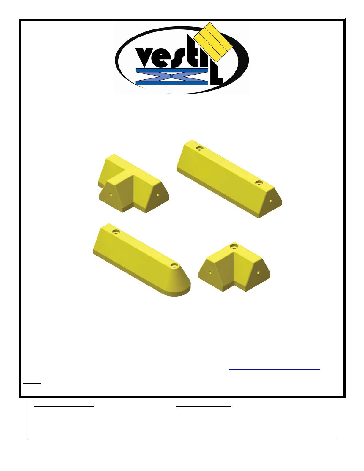
MPG-SERIES
MODUGUARD MODULAR CURBS
INSTRUCTION MANUAL
VESTIL MANUFACTURING CORP.
2999 NORTH WAYNE STREET
P.O. BOX 507, ANGOLA, IN 46703
TELEPHONE: (260) 665-7586 -OR- TOLL FREE (800) 348-0868
FAX: (260) 665-1339
URL: WWW.VESTILMFG.COM EMAIL: SALES@VESTIL.COM
NOTE: Compliance with regulations, codes, and/or statutory (non-voluntary) standards enforced in the
location where the speed bump is installed is exclusively the responsibility of the end-user.
Table of Contents Table of Figures
Product Introduction………………………... 2 Installation diagram……………...…….………… ………… 3
Safety Principles……………………............. 2
Installation Instructions………….…............ 3
Inspections & Maintenance………………… 3
Copyright 2011 Vestil Manufacturing Corp.
1 of 3
Page 2
1st edition 1211 12/21/2011 MPG-series installation instructions.doc
PRODUCT INTRODUCTION
Dimensions and other product specifications appear in the following table:
Model
MPG-C 21¼ (~54cm) Center piece 2 13 (~5.9kg)
MPG-E 21¼ (~54cm) End piece 2 13 (~5.9kg)
MPG-T 12 (~30.5cm) 3-Way connector 1 11 (~5kg)
MPG-L 8¾ (~22.2cm) 2-Way, 90° connector 1 8 (~3.6kg)
MPG-ABK-1 Anchor bolt kit for concrete for models MPG-T and MPG-L 0.5 (~0.23kg)
MPG-ABK-2 Anchor bolt kit for concrete for models MP G-C and MPG-E 1 (~0.45kg)
Safety Principles
Vestil manufactures several distinct models of glue-down speed bump. Each speed bump conforms to the generalized
specifications disclosed in this manual and fulfills our demanding standards for quality, safety and durability.
Vestil Manufacturing Corp. recognizes the critical importance of workplace safety. Each person who might
participate in the assembly, installation, use or maintenance of the product must read this manual and fully
understand the directions BEFORE installing the product and before performing maintenance on it. Failure to
adhere to the directions in this manual might lead to serious personal injury.
Vestil is not liable for any injury or property damage that occurs as a consequence of failing to heed the instructions
in this manual. Furthermore, failure to exercise good judgment and common sense may result in either property
damage or serious personal injury or both. Such failure is solely the fault of the person(s) who acted without good
judgment. Although Vestil diligently strives to identify foreseeable, hazardous situations, this manual cannot address
every conceivable danger. The end-user is ultimately responsible for exercising sound judgment at all times.
This manual uses SIGNAL WORDS to classify personal injury risks or situations that might lead to property damage,
as well as to draw attention to safety message(s). The reader must understand that each signal word indicates the
seriousness of the described hazard.
Identifies a hazardous situation which, if not avoided, WILL result in DEATH or SERIOUS
Identifies a hazardous situation which, if not avoided, COULD result in DEATH or SERIOUS
Indicates a hazardous situation which, if not avoided, COULD result in MINOR or MODERATE
Identifies practices likely to result in product/property damage, such as operation that might damage
Failure to read and understand the instructions included in this manual before installing or maintaining the
speed bump constitutes misuse of the product. Study the entire manual before you use the product for the first
time and as necessary thereafter. DO NOT attempt to resolve any problem with the product unless you are authorized
to do so and are certain
INJURY. Use of this signal word is limited to the most extreme situations.
INJURY.
injury.
the product.
Thank you for purchasing an MPG-series modular curb. Our curbs are durable, high-quality
products rigorously engineered for dependability and simple installation. Although installation
and maintenance procedures are intuitively obvious, any person who might install or maintain
this product must be familiar with the instructions provided in this manual.
Overall width in
inches (~cm)
Shape and Bolts required to
secure to surface
Net weight in
pounds (~kg)
that it will be safe to use afterwards.
Improper or careless installation might result in serious personal injuries sustained by motorists and/or
bystanders.
Immediately replace any curb segment that becomes structurally compromised. DO NOT keep a damaged curb
segment in service. Follow the inspection recommendations presented below to determine whether a segment should
be replaced.
DO NOT modify the curb or the anchoring hardware. Unauthorized modifications might compromise the stability of the
curb or of the anchor points.
Copyright 2011 Vestil Manufacturing Corp.
2 of 3
Page 3

1st edition 1211 12/21/2011 MPG-series installation instructions.doc
A
Installation
Step 1: Prepare the surface (road) where the curb will be installed. Thoroughly sweep the surface/road where the curb
will be installed. Allow the surface to dry completely, if necessary. Mark the concrete with the location of each bolt hole.
Step 2: If multiple curb segments must be fastened together to form the desired configuration, connect the segments
before proceeding to step 3. [NOTE: An assembly of multiple segments will be heavy; connect only as many segments
as you can comfortably manipulate.] Connect adjacent curb sections using alignment pins as shown in the diagram
below. Drive a pin into one of the pin holes with a 2lb. sledge hammer; then align the pin hole of the adjacent curb
segment with the end of the pin that was just driven into the other section.
hammer the adjacent curb segment onto the pin.
Connecting pin
pply weight to the first curb section and
: Drill 13/16in. (~2.1cm) diameter holes in the concrete to a depth of approximately 6in. (locations shown as X’s in
Step 3
the diagram above).
Step 3: Press/tap the anchor sleeves into the drilled holes until they are at least flush with the road surface or slightly
lower.
Step 4: Slide a washer onto each lag bolt; then insert the bolts into the bolt holes in the curb. Align the ends of the bolts
with the holes drilled into the surface. Firmly press down on the curb and tightly fasten the bolts to the anchors.
Anchor bolt hardware kit
Inspections & Maintenance
At least once per month:
Try to wiggle the curb to assess the soundness of the connections between the anchor bolts and the surface. If the
curb can wobble, determine which connection(s) is loose, and then try to secure the curb by tightening the loose
bolt(s). If the anchors are too loose to prevent the curb from wobbling, install the curb in a different location where the
surface is sound.
Closely inspect the curb for damage (cracks, deformation, etc.). If the speed bump is cracked or splitting, replace it.
Wipe dirt and other filth from the surface of the curb. The curb is yellow to provide a sharp contrast with the
surface/road.
Copyright 2011 Vestil Manufacturing Corp.
3 of 3
 Loading...