

Page 1
12/23/05
O
10/22/05 23-126-120.doc
VESTIL MANUFACTURING CORP.
2999 N. Wayne St., Angola, IN 46703
Ph: 260-665-7586 · Fax: 260- 6 65-1339
E-mail: sales@vestil.com · Website: www.vestil.com
WNER’S
MANUAL
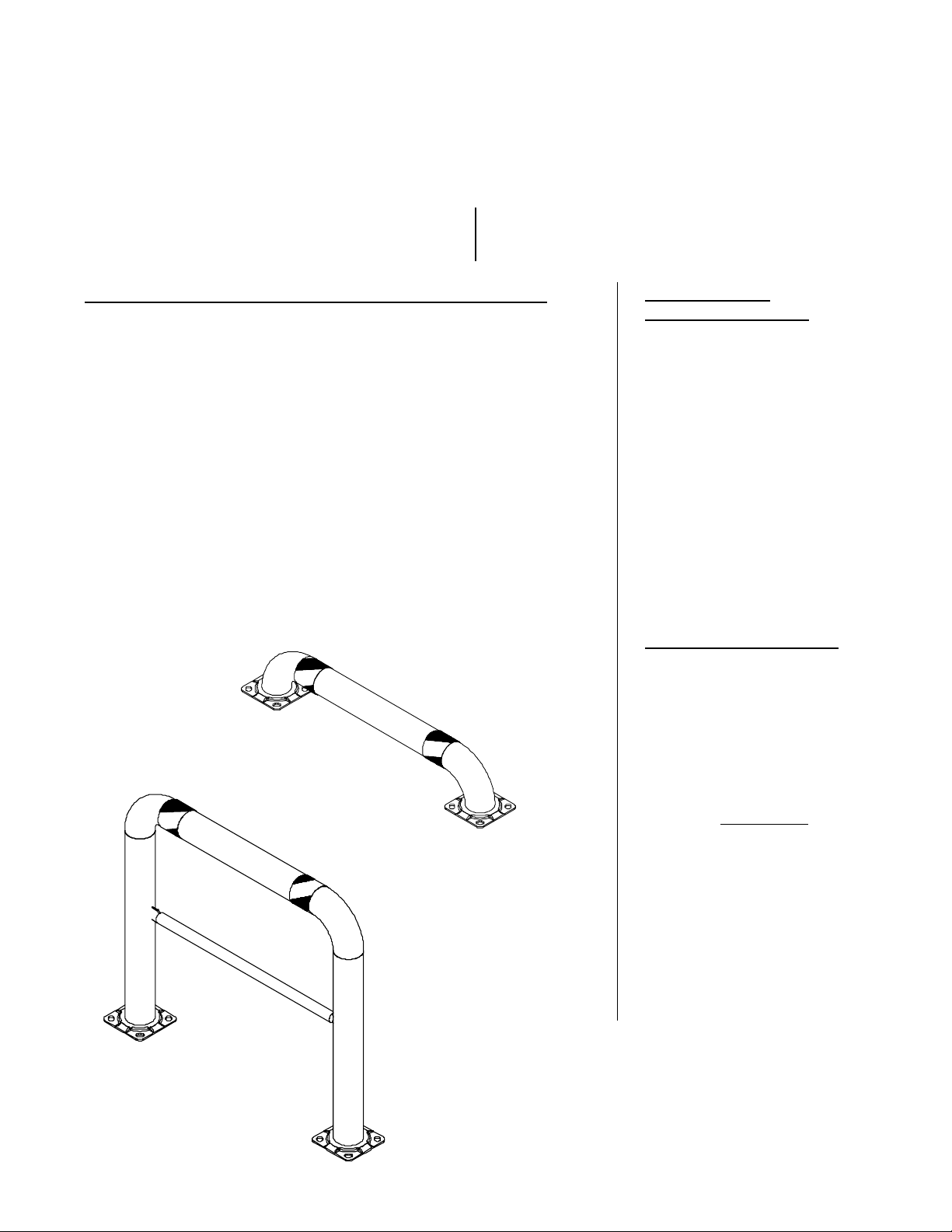
MODEL HPRO-48-42-4 / LPRO-48-16-4
Serial number ____________
Assembly / Installation Instructions ………………..… 2
Masonry Instillation Guidelines ……………………….3
Warranty …………………………………….……..…. 4
Routine Maintenance and Safety Checks………………2
Safety Label Identification .............................................4
IMPORTANT NOTES, WARNINGS AND SAFETY INSTRUCTIONS
Ensure that all employees understand and follow the following.
* Failure to read and understand this owner’s manual before using or
servicing the high / low profile guards constitutes a misuse of the
product. All persons who will install or care for this product must be
familiar with this material.
o Ensure that all safety labels stay in place and are legible.
o Do not use the high / low profile guard if any damage is observed.
o The high / low profile guard is intended for use only on concrete surfaces of
sufficient strength and condition to be adequate for anchoring.
o Contact the manufacturer for any needed MSDS information.
o Do not perform any modifications to the high / low profile guard without
the manufacturer’s approval. Failure to receive authorization for
changes to the equipment could void the warranty.
o Maintenance and repairs are to be done only by personnel qualified to
perform the required work. Consideration will not be given for warranty
repair charges without prior written authorization by the manufacturer.
WHEN ORDERING
REPLACEMENT PARTS:
We take pride in using quality
parts on the equipment we
manufacture. We are not
responsible for equipment
problems resulting from the use
of unapproved replacement
parts.
To order replacement or
spare parts for this equipment,
contact the factory.
In any communication with
the factory please be prepared
to provide the machine’s serial
number, which is indicated on
the machine dataplate.
RECEIVING INSTRUCTIONS
It is possible that the unit
could incur damage during
transit.
Inspect the unit closely when
it arrives. If you see evidence
of damage or rough handling to
either the packaging or to the
product when it is being
unloaded, immediately
note of it on the Bill Of Lading!
It is important that you
remove the product’s packaging
upon its arrival to ensure that
there is no concealed damage
or to enable a timely claim with
the carrier for freight damage.
Also verify that the product
and its specifications are as
ordered.
make a
ESTIL MFG. CO. 1
V
Page 2

concrete anchors, installation, 1005.doc
INSTALLATION (AND/OR ASSEMBLY) INSTRUCTIONS
Review this entire page before installing the high / low profile guard.
Consult the factory in the event there are any questions or problems at the time of installation, or for information
regarding optional features not covered by the owner’s manual.
The high / low profile guard must be removed from the shipping wood and securely anchored to the floor before use!
• Modifications or additions to the high / low profile guard without prior manufacturer’s authorization may void the high /
low profile guard’s warranty. The addition of ancillary equipment to the high / low profile guard may necessitate that
its load capacity be reduced.
• The installation must be made so that it complies with all the regulations applicable to the machine and its location.
The end-user must verify that the supplied equipment is installed so it will be suited to the environment in which it will
be used.
• Suitably trained personnel that have access to the appropriate equipment must perform installation.
---------------------------------------------------------------------------------------
For a typical installation of a standard high / low profile guard you will need the following:
1. A fork truck or hoisting means to unload the high / low profile guard from the freight truck and set it into place.
2. A smooth, level, and adequately strong concrete surface on which to mount the high / low profile guard.
3. Concrete anchors, a masonry drill, a masonry bit, hand tools, grout, and steel shims. Consult the building’s architect or
facility engineer to determine the best size and type of hardware with which to anchor the machine to the floor.
To install a standard high / low profile guard:
1. Move the high / low profile guard into place with straps or forks placed around it.
2. Anchor the frame to the floor through the 1” holes located on the bottom plate.
3. Clean up any debris, and verify that all of the safety labels are in good condition.
Note: See Installing Masonry Anchors section for instillation Guidelines.
ROUTINE MAINTENANCE & SAFETY CHECKS
(A) Inspect weekly for:
1.) The integrity of the frame anchor bolts, and for cracks in the concrete around them.
2.) Damage or structural deformation to the guard.
3.) All the safety labels being in place and in good condition.
2 of 4 Vestil Mfg Co / T&S Eqpt Co
Page 3

concrete anchors, installation, 1005.doc
INSTALLING MASONRY ANCHORS
The most important factor in choosing the proper anchor is the type of load it will carry. Shear loads are caused when the
weight of the fixture exerts force parallel to, or along, the surface of the concrete. Tensile loads are caused when the fixture
exerts force perpendicular to, or away from, the concrete surface.
Because precise knowledge of the condition of concrete at a given location is typically lacking, the standard recommendation is
that the anchor you choose should be rated for about four times the load’s weight it will carry if it will bear a static load, and eight
times the load’s weight if it will carry a dynamic or impact load. Static loads are loads that merely sit or hang without ever
experiencing a change in load conditions. Impact, or dynamic, loads have forces that vary in some way, such as when a load is
driven across an edge-of-dock dockleveler or a speed bump.
The holding power of any anchor depends on: the quality of the concrete -- if the concrete is old and crumbly, the holding
power of the fastener will be reduced, and; its position -- if the anchor is placed near the edge of the concrete, or if two anchors
are placed too close together, the force generated by the anchor might break the concrete.
* An anchor should be placed no closer to the edge of the concrete than the distance equal to five times the anchor’s width .
Therefore, a ½" diameter anchor should be no closer than 2½" (½” times five) from the edge of the concrete. Also, two anchors
should never be placed closer than ten times the anchor’s width from each other. In other words, two ½" anchors should be at
least 5" (½" x ten) apart.
♦ Two types of one-piece, mechanical expansion anchors are popular.
Sleeve anchors have a steel sleeve on the shank, split at the bottom so it can expand. The bolt has a cone-shaped plug at the
base, and a nut on the top. When you place the anchor in the hole and tighten the nut, it draws the bolt upward, pulling the plug
into the sleeve and expanding it against the hole. Once installed, sleeve anchors cannot be removed. They are available in a
variety of head styles, however -- a removable hex head, an acorn nut, or either round- or flat-head screws.
The shank of a wedge anchor is similar to a sleeve anchor -- a solid shank, threaded at the top and with a cone-shaped plug at
the bottom. But the shank of a wedge anchor is grooved on opposite sides. In each groove is a rectangular shank with a spadeshaped wedge on the end. As the nut on top is tightened, the washer pushes the rectangular shanks down, which spreads the
wedges over the plug. A wedge anchor cannot be removed once it is installed. Wedge anchors always have a hex head screw with a
washer so the material can be removed and reinstalled.
* As a rule, use sleeve anchors when working with soft concrete or installing them in the mortar joints between block or brick.
Also use sleeve anchors when you suspect that the concrete may have voids in it. Sleeve anchors have a larger bearing surface
than wedge anchors. Use wedge anchors for maximum holding power in hard concrete.
♦ Once the proper type of anchor is determined, select the size of fastener that is closest to the size of the anchoring hole in
the product. Anchoring products’ specifications vary from one manufacturer to the next -- if the manufacturer's installation
instructions differ from the information in this document, always follow the manufacturer's instructions. When drilling a
hole for a masonry screw, it is a good idea to utilize the special bit sold by the screw manufacturer. Proper hole sizing is
critical for optimal holding power. Never use a dull bit, because it tends to produce a larger hole than the same size of
sharp bit. When drilling large holes in masonry, it is much easier and more accurate to start with a smaller bit and step up
gradually to the required bit diameter. Eye protection and a dust mask should be worn when drilling and cleaning the holes.
• To install wedge or sleeve anchors, first position the material you want to anchor. Mark the
locations of the product’s anchor holes on the concrete. The product can be left in place if
there is adequate clearance to allow for drilling the holes. Use a hammer drill to drill the holes
in the concrete at the product’s bolt hole location. Make sure the holes are the specified
diameter for the anchor that you plan to use, and at least ¼" deeper than the length of the
anchor. Blow the dust out of the drilled holes with compressed air or a blow-out bulb. Place
the product over the anchor holes and insert the anchors into the holes. Use an appropriatelysized washer between the bolt head and the product if necessary to prevent the product’s hole
from eventually pulling over the bolt head. Tighten a sleeve anchor two to three turns to
expand it. Tighten a wedge anchor three to five turns. The anchor manufacturer’s instructions
might specify that the anchor is to be tightened with a torque wrench to a certain number of
foot-pounds.
• Installing a two-step mechanical anchor: For a two-step anchor, tap the
anchor into the hole, then position the item being mounted and install the
fastener. Again, use washers if necessary if there is a possibility that the product
could eventually pull off of the bolt head. Tighten the fastener until its head is
fully seated against the mounted item and secure in the hole. Do not over tighten
it, or you might break the fastener or ruin the anchor’s bond with the concrete.
Note: To determine the proper type of concrete fastener to use for a specific
application, consultation with the building’s architect or facility engineer
is recommended.
3 of 4 Vestil Mfg Co / T&S Eqpt Co
Page 4

concrete anchors, installation, 1005.doc
SAFETY LABEL IDENTIFICATION
* Product safety signs or labels should be periodically inspected and cleaned by the product users as necessary to
maintain good legibility for safe viewing distance -- ANSI 535.4 (10.21). Contact the manufacturer for replacement
labels.
RODUCTS’ WARRANTY
P
90 DAY LIMITED WARRANTY
The manufacturer warrants for the original purchaser against defects in materials and workmanship under normal use for 90 days
after date of shipment. Any part that is determined by the manufacturer to be defective in material or workmanship and returned
to the factory, shipping costs prepaid, will be, as the exclusive remedy, repaired or replaced at our option. Labor costs for warranty
repairs and/or modifications are not covered unless pre-approved by the manufacturer or done at the manufacturer’s facilities. Any
modifications performed without prior written approval of the manufacturer may void warranty. This limited warranty gives
purchaser specific legal rights, which vary from state to state.
All specifications are subject to change without notice.
LIMITATION OF LIABILITY
To the extent allowable under applicable law, the manufacturer’s liability for consequential and incidental damages is expressly
disclaimed. The manufacturer’s liability in any event is limited to, and shall not exceed, the purchase price paid. Misuse or
modification may void warranty.
Warranty does not cover labor or consequential damages including, but not limited to, business interruption costs, lost profits, or
lost business opportunities.
WARRANTY DISCLAIMER
The manufacturer has made a diligent effort to accurately illustrate and describe their products. However, such illustrations and
descriptions are for the sole purpose of identification, and do not express or imply a warranty that the products are merchantable or
fit for a particular purpose, or that the products will necessarily conform to the illustrations or descriptions.
The provisions of the warranty shall be construed and enforced in accordance with the Uniform Commercial Code and laws as
enacted in the State of Indiana.
DISPOSITION
Our company will make a good faith effort for prompt correction or other adjustment with respect to any product that proves to be
defective within the Limited Warranty Period. Warranty claims must be made in writing within said year.
4 of 4 Vestil Mfg Co / T&S Eqpt Co
 Loading...