

Page 1
VESTIL MANUFACTURING CORPORATION
2999 North Wayne St., P.O. Box 507
Angola, IN 46703 USA
Phone (260) 665-7586 • Fax (260) 665-1339
www.vestil.com • sales@vestil.com
Contents
Warnings and Safety Instructions .................... 1
Receiving Instructions ..................................... 1
Operating Instructions - HT, LDLT ................... 2
Instructions for Battery-Powered Units ............ 3
Power Unit's Operation - HT, LDLT ................. 4
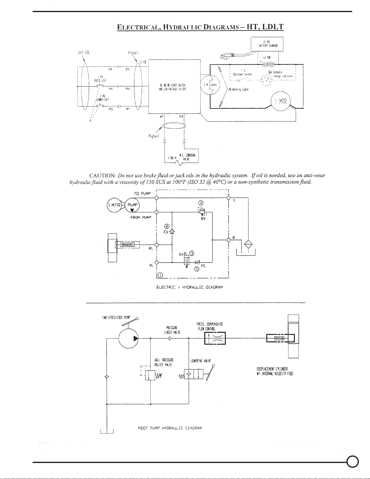
Electrical, Hydraulic Diagrams - HT, LDLT ..... 5
Routine Maintenance & Safety Checks ........... 6
Trouble Shooting Guides - HT, LDLT ............. 7
Revised 10-03 21-126-102
A company dedicated to solving ergonomic and material
handling problems since 1955.
OWNER'S
MANUAL
HYDRAULIC POST TABLES & LONG DECK CART
Model HT, LDLT
1 & 2-Post Hydraulic Parts/Drawing .............8-9
4-Post Hydraulic & DC Parts/Drawing ......10-11
Foot Operated Jack Parts/Drawing ..........12 -15
2-Speed Operating Instructions .....................16
Trouble Shooting Guide ...........................17-18
2-Speed Foot Pump Parts/Drawing ........ 19 - 20
Warning Labels .............................................21
Warranty ........................................................ 22
WARNINGS & SAFETY INSTRUCTIONS
Insure that all employees understand and follow the
following instructions.
• Read and understand the owner's manual before using or
servicing the table.
• For battery-powered units, review the additional warnings
included elsewhere in this manual.
• Do not use the table if any damage or unusual noise is
observed.
• Always watch the table and any load on it carefully when
it is being moved or used.
• Avoid sudden stops or quick turns to prevent accidental
tipping of the table.
• Use caution if you slide a load onto the table top.
• The table's load must be centered and evenly distributed
on the table.
• Do not perform any modifications to the table without the
manufacturer's approval. Failure to receive authorization
for changes to the equipment could void the warranty.
• Maintenance and repairs are to be done only bypersonnel
qualified to perform the required work.
• Do not use brake fluid or jack oil in the hydraulic system.
If oil is needed, use an anti-wear hydraulic oil with a
viscosity grade of 150 SUS at 100°F, (ISO 32 @ 40° C),
or a non-synthetic transmission fluid.
• Use only replacement parts either supplied or approved
by the manufacturer.
RECEIVING INSTRUCTIONS
Every unit is thoroughly tested and inspected prior to
shipment. However, it is possible that the unit may incur
damage during transit. If you see damage when unloading,
make a note of it on the SHIPPER RECEIVER.
Remove all packing and strapping material, inspect for
damage. IF DAMAGE IS EVIDENT, FILE A CLAIM WITH
THE CARRIER IMMEDIATELY! Also, check the platform
size, type of power unit, etc., to see that the unit is correct for
the intended application.
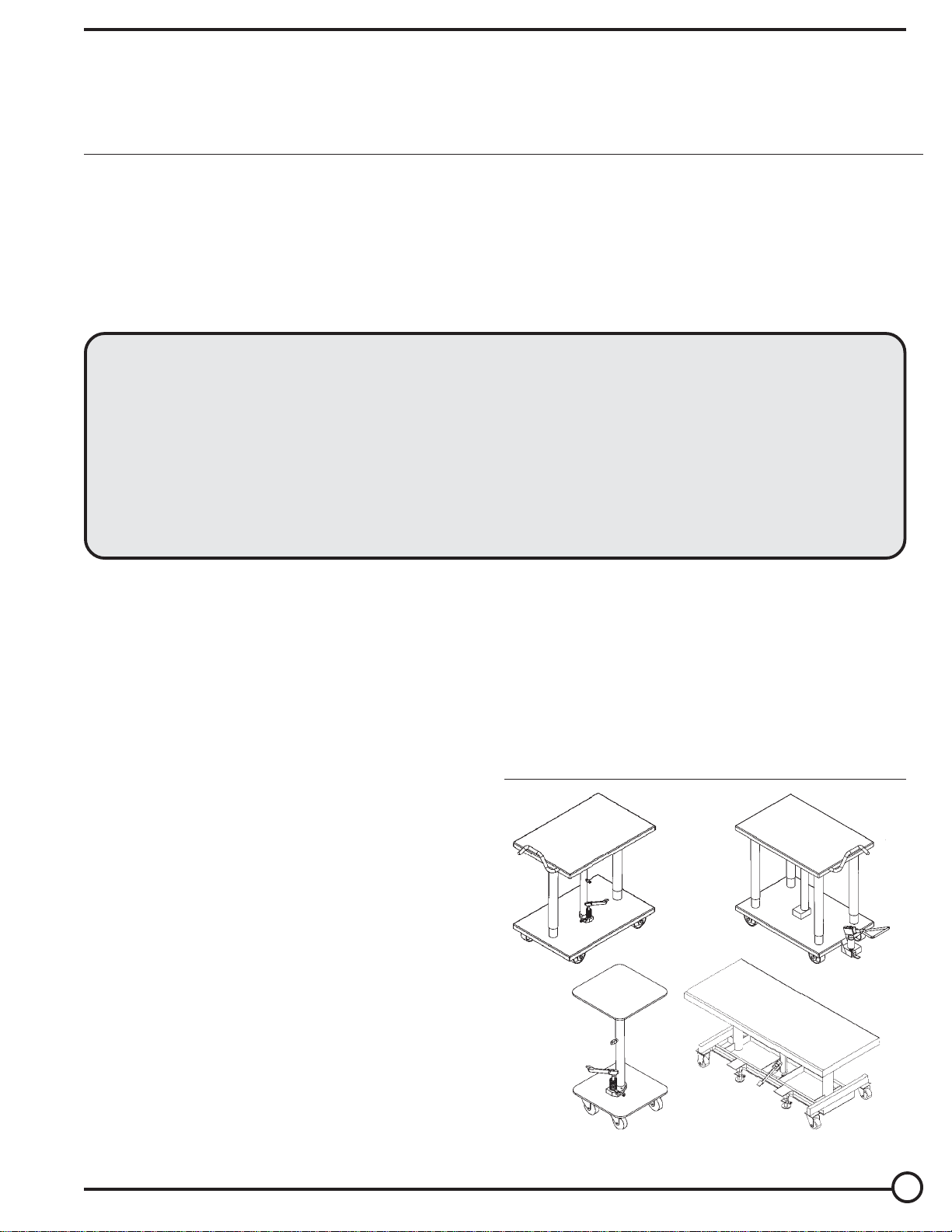
4-POST
2-POST
Long Deck
SINGLE POST
HYDRAULIC POST TABLES
& LONG DECK CART
1
Page 2

OPERATION INSTRUCTIONS - HT, LDLT
LOADING:
The load rating, in pounds, is shown on the capacity tag located on the base. It indicates the net capacity of the table, assuming
a centered load. Permanent damage to the table or injury to personnel could result from exceeding the listed capacity.
The load size should not exceed the table dimensions by more than 50% and should not exceed twenty-four inches in height.
Do not use the base of the hydraulic table as a storage shelf.
OPERATION:
The manually-powered hydraulic tables are furnished with a foot-pump.
On the single and two-post tables, step on the foot treadle to raise the table and step on the release lever on the right side
of the pump to lower the table.
The four-post table has a two-speed foot pump, separate from the lifting cylinder. Step on the foot treadle to raise the table.
You can change the pump from the low-volume to high-volume by pulling the slide on top of the foot pump back toward the
foot treadle.
The DC-powered table is furnished with either a constant-pressure (dead-man style), push-button (standard), or twin foot switch
(optional) control.
Pressing the "UP" push-button or foot switch will turn the power unit to raise the platform. The platform will raise only while
the control is pressed. Upon releasing the control, the platform will stop and hold its position.
Pressing the "DOWN" push-button or foot switch will energize the lowering valve to allow the platform to descend. Again,
releasing the control will stop the platform movement and the unit will hold its position. Be certain no part of any person or
object is under any part of the platform before lowering the unit.
Attempting to raise the platform when the battery is low will cause the motor relay protection to prevent the motor's operation.
Adequate battery voltage is indicated by a green LED on the motor relay. See the next page for more notes regarding operation
of battery-powered units.
SAFETY:
Keep all personnel clear of the machine when it is in operation.
Do not exceed the table's load rating.
Use caution to avoid tipping the table when placing or sliding a load onto or off of the table.
Avoid obstacles that can cause the base to sudden stop when moving a loaded table, such as cracks in the floor or the corners
of machines, etc. Doing so could cause the post table to tip over or allow the load to slide off the table.
Never use the table if it is in need of repairs or if it seems to be malfunctioning.
Notify your maintenance personnel if you notice anything out of the ordinary, such as odd noises, erratic motion, or damage
to any part of the table or its components.
ORDERING REPLACEMENT PARTS:
We take pride in using quality parts on the equipment we manufacture. We are not responsible for equipment problems resulting
from the use of unapproved replacement parts.
To order replacement or spare parts for this equipment, contact the factory.
In any communication with the factory, please be prepared to provide the machine's serial number, which is indicated on the
machine dataplate.
2
Page 3

ADDITIONAL INSTRUCTIONS FOR BATTERY-POWERED UNITS
WARNING!
! Working with or near lead batteries is dangerous. Batteries contain sulfuric acid and produce explosive gases. A battery
explosion could result in loss of eyesight or serious burns.
! Do not smoke or allow a spark or flame near batteries. Charge batteries in locations which are clean, dry, and well-ventilated.
! Do not lay tools or anything metallic on top of any battery. All repairs to a battery must be made by experienced and qualified
personnel.
! When working with batteries, remove personal items such as rings, bracelets, necklaces, and watches. Batteries can
produce enough energy to weld jewelry to metal, causing a severe burn.
! Always have fresh water and soap nearby in case battery acid contacts skin, clothing, or eyes.
! Operating the battery with a low battery voltage can cause premature motor contact failure.
! Do not expose the lift or charger to rain or adverse conditions.
! Replace defective cords or wires immediately.
! Check the battery's water level frequently.
BATTERY CHARGER OPERATING INSTRUCTIONS:
Never operate the charger with either of the cables coiled. Operating the unit with the cord wrapping around itself can cause
the cord to overheat, melt, and cause a short-circuit or a fire.
Plug the charger into a standard 115V receptacle. If an extension cord must be used, keep it as short and as large as possible.
A small cord will decrease the output of the charger due to the voltage in the line. This will increase the charging time. It can
also cause the 115V cord to overheat.
When properly connected, the charge LED will indicate the status of charge flowing to the battery, as follows:
Red only - the charger is providing full output to the battery.
Both red and green - the charger is "topping off" the battery.
Green only - the charger is providing a "float," or maintenance, charge.
Remember to unplug the charger before moving the equipment. Failure to do so could cause damage to cords, receptacles,
and other equipment.
TROUBLESHOOTING:
If the unit does not operate, check all the wiring connections to make sure they're both mechanically and electrically sound
- specifically at the battery, the motor, and at any location a wire is connected to the chassis. Also make sure the quick-connect
plug on the end of the pendant control cord is plugged in correctly.
A full-charged lead acid battery in good condition at room temperature should read 12.65 volts. At 11.9 volts it is considered
to be fully discharged and in need of charging. When checking battery voltage, wait at least 1/2 hour after the charger has
been turned off before checking the battery's voltage. If the motor doesn't run, observe the green LED on the motor relay. If
it is not lit, or if the LED goes out when the "UP" control is pressed, the battery voltage should be checked with a voltmeter.
If the batteries aren't being charged by the charger, check the output charger fuse. If it is good, check the battery's state of
charge with a voltmeter.
3
Page 4

THE POWER UNIT'S OPERATION - HT, LDLT
The electric/hydraulic table utilizes an electric motor directly coupled to a gear-type hydraulic pump to produce the
needed fluid pressure and flow to allow the cylinders to perform the work of lifting the table load.
A hydraulic manifold houses the hydraulic control components, and is bolted directly onto the gear pump.
The power unit's hydraulic components are all treated for 3,000 psi working pressure.
Important parts of the power unit include:
• The electric motor operates on 12 VDC.
• The gear pump. Its shaft is coupled directly to the shaft of the electric motor.
• The check valve. Its purpose is to prevent the backflow of fluid through the pump. In this way it allows the table
to be held at a given elevation indefinitely.
• The pressure relief valve. Its job is to open a path for fluid to flow back to the reservoir in the event that the fluid
pressure built up by the pump exceeds 3,000 psi. Thus the pump cannot generate more than 3,000 psi.
• The lowering solenoid valve. This is an electrically-operated cartridge valve. It contains a screen to keep
contaminants from entering the valve.
• The pressure-compensated flow control spool. This rests under the lowering valve and regulates the fluid flow back
to the reservoir when the valve opens. It allows the table to always lower at the same rate regardless of whether there
is a load on the table or not.
• The hydraulic lift cylinder. On units with a motor or two-speed foot pump, the cylinder has a bleeder valve located
at their top end to allow air to be bled from the hydraulic system.
• The safety velocity fuse. This is a device that is installed in the cylinder's hose port. It closes quickly in the event
of a catastrophic hose failure to prevent the table from collapsing down. The table remains stationary until pressure
is reapplied to the system.
• The hydraulic fluid. The system uses HO150 hydraulic fluid. Any anti-wear hydraulic oil with a viscosity grade of
150 SUS at 100°F (ISO 32 @ 40°C) such as AW 32 or non-synthetic transmission fluid is acceptable.
When the table is to be raised, press the "UP" push-button or foot switch. The motor turns, and in turning it spins the
hydraulic gear pump. Oil is drawn from the reservoir through the suction filter and into the pump. The pump pushes
the then-pressurized oil through the check valve and out to the lift cylinders.
When the table is to be lowered, press the "DOWN" push-button or foot switch. The lowering valve opens, bypassing
the check valve and allowing the oil in the cylinders to return back to the reservoir through the return hose. The rate
at which the table lowers is regulated by the internal pressure-compensated flow spool.
In the event that the table creeps down slowly after releasing the "DOWN" control, it will be necessary to remove the lowering
cartridge valve for inspection and cleaning, as follows:
• Lower the table entirely.
• Remove any load from the table.
• Remove the nut holding the solenoid coil on the valve stem, remove the coil, and then unscrew the valve from
the manifold.
• Inspect the valve for contaminants, and the valve's o-rings and backup washers for cuts, tears, or other damage.
• With the valve immersed in mineral spirits or kerosene, use a thin tool such as a small screwdriver or a small hex
wrench to push the poppet in and out several times form the bottom end of the valve. The valve should move
freely, and 1/16" from closed to open position. If it sticks in, the valve stem could be bent and will need to be
replaced if it doesn't free up after cleaning. Blow the valve off with a compressed-air gun while again pushing the
poppet in and out.
• Inspect the bottom of the manifold's valve cavity for contaminants.
• Again with the thin tool, press on the middle of the flow control spool located in the bottom of the cavity. It should
move down and back up freely.
• Reinstall the valve into the manifold, tightening the valve with approximately 20 lb-ft of torque.
If the table lowers extremely slowly, or not at all, the cylinder's velocity fuse could be closing. This can be caused by air
in the hydraulic cylinders. To bleed the air from the system:
• Lower the table entirely.
• Remove any load from the table.
• Hold a rag over the cylinder's bleeder valve (it looks like a grease zirk) and open the valve about 1/2 turn with a
1/4" or 5/16" wrench. Oil and air will sputter from the valve - once no air is observed, close the valve.
4
Page 5
5
Page 6

ROUTINE MAINTENANCE & SAFETY CHECKS - HT, LDLT
Care should be taken to identify all potential hazards and comply with applicable safety procedures
before beginning work.
Only qualified individuals trained to understand mechanical devices and their associated electrical and
hydraulic circuits should attempt troubleshooting and repair of this equipment.
(A) Before each use inspect the following, where applicable:
1.) Frayed wires.
2.) Oil leaks.
3.) Pinched or chafed hoses.
4.) Damage or structural deformation to the structural members, the
cylinder, the foot pump, etc.
5.) Unusual noise or binding or evidence thereof.
6.) Proper functioning of all limit switches.
(B) Inspect monthly for, where applicable:
1.) The oil level. Oil should be 1" to 1 1/2" below the cylinder's
or the reservoir's fill hole with the lift in the fully lowered position.
2.) Oil leaks.
3.) Worn or damaged hydraulic hoses and electrical wires, if applicable.
4.) Integrity of the retaining rings and pins at all pivot points.
5.) Looseness, wear, or damage to the casters' bearings, mounting
hardware, or surface material.
6.) Proper water level in the battery. (DC units only.)
7.) Unusual noises.
8.) Information and warning labels being in place and in good condition.
9.) The need to clean off dirt and debris.
(C) Yearly inspection
The oil should be changed if the oil darkens, becomes gritty, or turns a milky color
(indicating the presence of water). Replace with an anti-wear hydraulic oil with a
viscosity grade of 150 SUS at 100°F, (ISO 32 @ 40°C). Ex: AW 32 or HO 150
hydraulic fluid, or non-synthetic transmission fluid.
6
Page 7

TROUBLESHOOTING GUIDE, DC UNITS - HT, LDLT
Before performing any task, always lower the table entirely.
Care should be taken to identify all potential hazards and comply with applicable safety procedures before beginning.
Only qualified individuals trained to understand mechanical devices and their associated electrical and hydraulic
circuits should attempt troubleshooting and repair of this equipment.
Consult the factory for any problems not addressed in this manual.
* Check the DC notes page for other troubleshooting notes specific to battery-powered units.
Problem:
1. Power unit doesn't run when "UP"
button is pressed.
2. Motor runs, but table does not move
or only moves slowly. Power unit not
noisy.
3. The power unit runs but makes a
higher-pitched sound; the table does
not move, or the table moves only
slowly.
4. Table raises, then drifts down.
5. Spongy or jerky table movement.
6. Table lowers too quickly.
7. Table won't lower.
8. Table lowers too slowly.
Possible Causes:
A. Upper-travel switch is engaged or
bad.
B. Push-button control cord not plugged
into motor relay assembly properly.
C. Bad motor relay assembly (green
LED not lit at all or turns off when the
motor relay pulls in).
D. Battery voltage low (green LED turns
off as or just after the motor relay
pulls in).
A. Pump is failing to build pressure.
B. Contamination holding open the
lowering valve or the check valve.
A. Pressure relief opening at full
pressure.
A. Contamination holding open the
lowering valve or the check valve.
A. Excessive air in the hydraulic
cylinder.
A. Flow control spool sticking.
A. Solenoid coil is bad.
B. Physical blockage of the structure.
C. Solenoid valve or suction hose
screen plugged.
A. Pinched hose.
B. Flow control spool sticking.
C. Velocity fuse locking (table only
slowly creeps down).
Action:
A. Inspect and test switch. Replace if
bad.
B. Verify that the push-button cable's
plug is connected properly to the
relay assembly's quick-connect.
C. Check for green LED on relay. Consult
the factory.
D. Test with meter. Charge battery if
low (< 12 volts). A fully charged
battery has 12.6 volts.
A. Consult the factory.
B. Remove and inspect. Clean per
instructions in this manual.
A. Check for structural damage or
binding of the posts, etc.
B. Check for table overload condition.
A. Remove and inspect. Clean per
instructions in this manual.
A. Bleed air from the bleeder valve at
the top of the cylinder.
A. Remove plug from FC port; push on
edge of flow spool to ensure it is fully
pressed into the cavity. Pull and
clean spool if dirty.
A. Check with multimeter on diodecheck
function. (Reading for ohms will not
provide an accurate test of the coil.)
B. Inspect for foreign material or
objects that might obstruct the table
or guide posts.
C. Remove and inspect. Clean per
instructions in this manual.
A. Check pressure, supply, and return
hoses for kinks.
B. Remove plug from FC port; push on
flow spool to ensure it is fully pressed
into the cavity. Pull and clean spool
if dirty.
C. Same as for jerky table movement.
7
Page 8

EXPLODED PARTS DRAWING
1& 2-POST HYDRAULIC TABLE
3a
6
1
2a
4
ITEM NO.
1
2a
2b
2c
3a
3b
4a
4b
5a
5b
6
6a
6b
A
B
C
a/l - Available at Local Hardware Store
DESCRIPTION
Foot Pump (FHJ-18 style)
Foot Pump Mt. Bolts 1/4-20 x 2
Nut 1/4-20 Nylock
Washer 1/2-20 Flat Washer
Casters 3-1/2 x 1-1/4 Polyurethane
Caster with Total Locks, Polyurethane
Bolt, Caster Mt. 1/4-20 x 3-1/2, or equivalent
Bolt 3/8-16 unc x 5 Carriage Bolt, or equivalent
Nut, Nylock Caster Mt. 1/4-20
Nut 3/8-16
Pin, Upper Cylinder Mt. (roller pin) 3/16 x 1-1/2
5 x 2 Poly-on-Steel Rigid Caster
5 x 2 Poly-on-Steel Swivel with Lock
Seal Kit Foot Pump
Caster Kit (includes either 3a or 3b)
HD Caster Kit (see page 10)
8
5
PARTS LIST
1 & 2-POST HYDRAULIC TABLES
ENGINEER NO.
01-640-030
a/l
a/l
a/l
16-132-003
16-132-002
a/l
a/l
a/l
a/l
a/l
16-132-022
16-132-03
01-136-412
21-154-009
16-154-020
*See page 9 for Two-Post Table Exploded Drawing
PART NO.
HT2-FTP
a/l
a/l
a/l
HT2-CSTR
HT2-CSTRTL
a/l
a/l
a/l
a/l
a/l
HT2-HDCSTR
HT2-HDLCSTR
HT2-KITA
HT2-KITB
HT2-KITC
QTY.
1
2
2
2
4
4
4
4
1
-
-
2
2
1
1
1
Page 9

EXPLODED PARTS DRAWING
2-POST HYDRAULIC TABLES
* See page 8 for Parts List
1
2b
6a
6b
4b
5b
1
2a
2b
* See page 8 for Parts List
3a
3b
4a
5a
9
Page 10

EXPLODED PARTS LIST
4-POST HYDRAULIC & DC POWERED POST TABLES
11
38
39
30
37 (NOT SHOWN)
31
32
13
5
4
12
6
7a,b
8a,b
15
14
1, 1a, 2, 3
10
34
Page 11

PARTS LIST
4-POST & DC POWERED HYDRAULIC POST TABLES
ITEM NO.
1
2
3
4a
4b
5
6
7a
8a
9
10
11
12
13
14
15
1a
DESCRIPTION
Foot Pump, Two Speed
Bolt, Foot Pump Mt. 3/8-16 x 3
Nut, Foot Pump Mt. 3/8-16
Cylinder 1-1/8 x 18
Cylinder 1-3/4 x 18
Bolt, Cylinder 3/8-16 x 1-1/4
Nut, Cylinder 3/8-16
Casters, Rigid 4 x 2 Phenolic
Caster, Swivel 4 x 2 Phenolic with Brake
Bolt, Caster Mt. 3/8-16 x 5 Lg.
Nut, Caster Mt. 3/8-16
Hose Assembly - Pressure
Hose Assembly - Return
Bolt Caster, 3/8-16 x 1 (6,000 lb. unit only)
Nut Lock, Caster 3/8-16 x 1 (6,000 lb. unit only)
Washer 3/8 (not shown) (6,000 lb. unit only)
Seal Kit for Foot Pump
ENGINEER NO.
01-640-004
a/l
a/l
21-021-006
21-021-005
a/l
a/l
16-132-016
16-132-148
a/l
a/l
21-523-001
21-523-002
a/l
a/l
a/l
01-136-441
PART NO.
HT4-2SFP
a/l
a/l
HT4-CYL
HT6-CYL
a/l
a/l
HT4-RGPHN
HT4-SWPHN
a/l
a/l
HT4-PSRHA
HT4-RTNHA
a/l
a/l
a/l
HT4-FP-SK
QTY.
1
2
2
1
1
2
2
2
2
4
4
1
1
16
16
16
1
ITEM NO.
30
31
32
34
35
36
38
37
39
DC POWERED POST TABLES
DESCRIPTION
Motor
Pump
Bolt Motor/Pump Mt. 3/8-16 x 1
Hand Control
Hydraulic Hose Assembly Pressure
Hydraulic Hose Assembly Return
Battery
Motor, Solenoid Smart Start Switch
Battery Box, Strap
ENGINEER NO.
01-135-042
01-143-010
a/l
01-522-022
21-523-003
21-523-004
21-139-003
15-022-004
21-154-010
PART NO.
HTDC-MTR
HTDC-PMP
a/l
HTDC-HC
HTDC-HHAP
HTDC-HHAR
HTDC-BATT
HTDC-SOL
HTDC-BBS
QTY.
-
-
-
-
-
-
-
-
-
A/L
A/K
Available at local hardware store
Available only with purchase of kit
11
Page 12

FOOT OPERATED JACK ASSEMBLY
MODEL FHJ-C
12
Page 13

Reference Model
Number Component Decription Number
FHJ-C-1-18
FHJ-C-1-24
FHJ-C-2
FHJ-C-3-18
FHJ-C-3-24
FHJ-C-4
FHJ-C-5
FHJ-C-6
FHJ-C-7
FHJ-C-8-18
FHJ-C-8-24
FHJ-C-9
FHJ-C-10
FHJ-C-11
FHJ-C-12
FHJ-C-13
FHJ-C-14
FHJ-C-15
FHJ-C-16
FHJ-C-17
FHJ-C-18
FHJ-C-19
FHJ-C-20
FHJ-C-21
FHJ-C-22
FHJ-C-23
FHJ-C-24
FHJ-C-25
FHJ-C-26
FHJ-C-27
FHJ-C-28
FHJ-C-29
FHJ-C-30
FHJ-C-31
FHJ-C-32
FHJ-C-33
FHJ-C-34
FHJ-C-35
FHJ-C-36
FHJ-C-37
FHJ-C-38
FHJ-C-39
FHJ-C-40
FHJ-C-41
FHJ-C-42
FHJ-C-43
FHJ-C-44
FHJ-C-45
FHJ-C-46
FHJ-C-47
FHJ-C-48
FHJ-C-49
FHJ-C-50
FHJ-C-51
FHJ-C-52
FHJ-C-53
FHJ-C-54
FHJ-C-55
FHJ-C-SK
10
11
12
13
14
15
16
17
18
19
20
21
22
23
24
25
26
27
28
29
30
31
32
33
34
35
36
37
38
39
40
41
42
43
44
45
46
47
48
49
50
51
52
53
54
55
1
1
2
3
3
4
5
6
7
8
8
9
Cylinder Assembly 18 Inch
Cylinder Assembly 24 Inch
O-Ring 31.5 x 1.8
Inside Cylinder Body 18 Inch
Inside Cylinder Body 24 Inch
O-Ring 31.5 x 1.8
O-Ring 34 x 3.5
O-Ring 56 x 3.5
Valve Plug
Lift Piston 18 Inch
Lift Piston 24 Inch
U-Packing UHS28
Dust Ring DH28
Washer
Pump Cylinder
Screw Plug
Steel Ball
Screw Plug
Cone Valve
Spring
O-RIng 28 x 2.4
Pump Piston
U-Packing UHS18
Dust Ring DH18
Lock Shaft
Spring Slide
Screw
Link shaft
Roller Guide
C-Ring
Foot Assembly
Rubber Rad
Press Set Screw
Spring
Single Vlave Pin
Single Vlave Pad
O-Ring 10 x 1.9
Steel Ball 5
Spring
Push Lever
O-Ring 7 x 1.9
Push Lever Pad
O-Ring 15 x 2.4
Lock Shaft
Twist Spring
Leading Pad
Discharge Foot Assembly
Socket Set Screw
Adjusting Screw
Hex Cap Nut
Steel Ball
Spring Seat
Adjusting Pressure Spring
Adjusting Pressure Plug
O-Ring 11 x 1.9
Fix Screw
Screw Air Breather
O-Ring 10 x 1.9
Seal Kit
13
Page 14

FOOT OPERATED HYDRAULIC JACK ASSEMBLY
MODEL FHJ
14
Page 15

PARTS LIST FOOT OPERATED HYDRAULIC JACK - MODEL FHJ-C
ITEM # PART NUMBER DESCRIPTION QUANTITY
1 FHJ-P103 Snap Ring 2
2 FHJ-P104 Spring Holder 1
3 FHJ-P102 Plunger 1
4 FHJ-P105 Pressure Spring 1
K 5 FHJ-P106 Rod Wiper 1
K 6 HYD-02-2706 O-Ring 1
7 FHJ-P113 Check Valve Plug 1
K 8 HYD-01-2514 O-Ring 1
9 PLT-P1036 Valve Spring 1
10 PLT-P1037 Cone Valve 1
11 PLT-P1038 Cone Valve Seat 1
K 12 HYD-01-0803 O-Ring 2
13 SB-9-32 Steel Ball 1
14 FHJ-P153 Roller 1
15 FHJ-P151 Snap Ring 4
16 FHJ-P152 Pedal Pin 2
17 FHJ-P168 Foot Pedal 1
18 SB-5-32 Steel Ball 1
19 FHJ-P111 Relief Seat 1
20 FHJ-P110 Relief Spring 1
21 FHJ-P109 Relief Plug 1
22 FHJ-P121 Lowering Pedal Spring 1
23 FHJ-P119 Lowering Pedal 1
24 FHJ-P147 Filler Breather Plug 1
25 FHJ-P150 Pedal Crimp Spring 1
26 FHJ-P148 Lock Washer 1
27 FHJ-P149 Screw 1
K 28 FHJ-P107 Back-Up Ring 1
K 29 FHJ-P166 Dust Seal 1
K 30 FHJ-P167 Rod Seal 1
K 31 CYL-M0010-020 Dyna Seal 1
32 FHJ-P135 Gland Nut 1
33 FHJ-P163 Socket Head Cap Screw 1
K 34 HYD-02-2811 O-Ring (Gland) 1
K 35 HYD-02-6038 O-Ring (Inner Tube) 2
36 FHJ-P156-3020-00 Piston Rod 1
37 FHJ-P141-2424 Inner Tube 1
38 FHJ-P101-2424 Base & Tube Weldment 1
39 FHJ-P129 Bolt 1
40 FHJ-P130 Lock Washer 1
41 FHJ-P1015 Valve Spring 1
42 FHJ-P123 Pressure Pin 1
K 43 HYD-01-2506 O-Ring 1
44 FHJ-P124 Bushing 1
K 45 HYD-01-2637 O-Ring 1
46 FHJ-P122 Lowering Spacer 1
47 FHJ-P120 Lowering Sleeve 1
48 FHJ-P128 Set Screw 1
49 FHJ-P118 Push Bolt 1
50 FHJ-P164 Lock Nut 1
51 FHJ-P139 Piston 1
52 FHJ-P165 Snap Ring 1
A FHJ-SK Seal Kit 1
K Available in seal kit only
15
Page 16

OPERATING INSTRUCTIONS FOR
TWO- SPEED FOOT PUMP
AIR BLEED PROCEDURE FOR TWO-SPEED
FOOT PUMP
FEATURES:
Your new lift equipment has been supplied with an exclusive
single-speed or two-speed foot pump. The internal features of
your pump includes a primary pressure relief, pressure
compensated return flow control valve, and an integrated
lowering valve. Replacements are necessary.
OPERATING INSTRUCTIONS:
Stay clear of moving parts. The platform will rise as the foot
pedal is pumped. Depressing the release lever will lower the
table at a controlled rate of descent. In the event the platform
has been overloaded, the pressure relief will open because of
excessive pressure buildup in the hydraulic system. Oil will
bypass into the reservoir. Never increase the pressure relief
setting more than necessary. Do not exceed the rated
capacity of your equipment.
TWO-SPEED SELECTION:
The two-speed hydraulic foot pump offers two "speeds". The
low speed products
speed products
low volume/high pressure.
high volume/low pressure.
The high
The operator has
the option of selecting the optimum pump speed for the
application at hand. Pump speeds are selected by sliding the
"lock collar" (Item #2 on the parts identification) in or out. An
occasional drop of oil will keep the collar working freely.
Whether your pump is a new installation, or has been recently
serviced, air has likely entered the hydraulic system. The
design of this pump includes an "air bleed screw" which will
aid in the removal of unwanted air from the foot pump area of
the hydraulic system. Use the following steps to remove this
air from the system.
1) Check all fittings to be sure they are tight. Ensure that the
oil is filled to within 1" of the top of the reservoir when the lift
is in the fully lowered position.
2) Locate the "air bleed screw" (item #34 on the pump body)
and loosen approximately 1/2 turn counterclockwise. As
soon as you have loosened the screw, slowly depress the
foot pedal. This unit will force the air out of the pump
chambers. Before you let the pump pedal return to the "up"
or "home" position, tighten the air bleed screw. This will
prevent air from reentering the pump chamber. Repeat the
above procedure until the pump chamber is completely filled
with oil and a "spongy" feel is no longer present. If the air
bleeding procedure has been successful, the feel of the pump
pedal will be firm and the complete stroke of the pump will
produce fluid flow.
Air can also become trapped in the hydraulic cylinder(s).
Review your owners manual for air removal instructions.
PRESSURE
CHECK VALVE
HYDRAULIC DIAGRAM FOR TWO-SPEED FOOT PUMP
2 SPEED
FOOT PUMP
PRESSURE
CHECK VALVE
ADJ. PRESSURE
RELIEF VALVE
LOWERING
VALVE
PRESSURE COMPENSATED
FLOW CONTROL
1GPM
TO CYLINDER
16
Page 17

HYDRAULIC FOOT PUMP --- TROUBLE SHOOTING GUIDE
TROUBLE SHOOTING
(Read all instructions thoroughly prior to performing any maintenance.)
SYMPTOMS
• Foot pumping action does not raise platform.
• Cylinder slowly drifts downward under load.
• Cylinder pumps up, but will not go down.
BLEEDER SCREW
CYLINDER
ROD
REMEDY
Tools required: 3 & 5 mm hex key wrenches
Standard head screwdriver
Adjustable wrench
1) Adjust Release Pedal
(Refer to figure below)
• Loosen setscrew on release pedal. Rotate
pedal counterclockwise until pedal touches
the base. While holding pedal, use hex key
wrench to turn release shaft counterclockwise
to stop. (NOTE: Do not loosen lock nut on
release pedal shaft.) Tighten pedal set
screws. Release pedal.
2) Check Fluid Level
• Remove fill/breather plug.
• Fluid should be filled to 2-2 1/2 inches from
bottom edge of hole when cylinder rod is in
the lowered position. If overfilled, fluid may
seep from fill/breather plug. (ISO #AW-32
ANTIWEAR HYDRAULIC PUMP OIL ONLY.
FLUID MUST BE CLEAN! STRAIN FLUID IF
NECESSARY).
FLUID FILL
LINE
RELEASE
PEDAL
FILL/
BREATHER
PLUG
PUMP PEDAL
RELEASE VALVE
ASSEMBLY CAP
OVERLOAD BYPASS
ADJUSTMENT SCREW
3 mm HEX
KEY WRENCH
3) Clean Release Valve Assembly
• Remove release valve assembly cap and
RELEASE PEDAL
PEDAL SET
SCREW
clean assembly (shown in exploded view.)
• While assembly is removed, pump foot pedal
vigorously at least five times.
CAUTION: Fluid will discharge from release
valve hole. This will dislodge any foreign
matter from the ball socket. Clear hole of
debris and reassemble release valve and
PRODUCT BASE
RELEASE PEDAL
ADJUSTMENT
tighten cap.
• Repeat procedure #2 to refill fluid.
4) Bleed Pump of Trapped Air
• Pump up cylinder at least 4 inches.
While putting pressure on the platform, release bleeder screw until fluid flows free and clear
from behind the screw. Then tighten bleeder screw and release pressure from platform.
Repeat procedure until no signs of air are present. If after following the above procedures
the problem still exists or if unit is leaking fluid, please contact the factory at (260)665-7586.
CCW
MOTION
17
Page 18

TROUBLESHOOTING GUIDE - 2-SPEED FOOT PUMP
Before performing any task, always lower the table entirely.
Consult the factory for any problems at time of installation or for any problems not addressed below:
*Check the DC notes page for other troubleshooting notes specific to battery-powered units.
Problem:
1. Platform does not raise when the foot
treadle is pressed. Foot treadle goes
down without excessive force.
2. Platform will fit under no load, but not
when fully loaded. Foot treadle goes
down without excessive force.
3. Platform raises with the pump
downstroke, but lowers with the pump
upstroke.
4. Platform raises, then drifts down.
5. Platform raises, but in smaller
increments than normal.
6. Excessive effort is required to operate
the foot pump.
7. Platform won't lower when the release
pedal is pressed or lowers too slowly.
•The hydraulic fluid. The
system uses HO150
hydraulic fluid. Any antiwear hydraulic oil with a
viscosity grade of 150 SUS
at 100°F (ISO 32 @ 40°C)
such as AW 32 or nonsynthetic transmission fluid
is acceptable.
8. Platform lowers too quickly.
9. Platform lowers with a jerky motion.
18
Possible Causes:
A. No oil getting through the pump - not
enough oil in reservoir, or the pump
has become "air-locked."
B. Pinched or kinked hose.
C. Relief valve is opening.
D. Inlet check valve assembly being
held open by contamination.
A. Same as above.
B. Contamination holding open the relief
valve assembly.
C. Air in the pump piston.
A. Outlet check valve assembly being
held open by contamination.
A. Same as above.
A. Contamination holding open the relief
valve assembly or the inlet check
valve assembly.
A. Operating pressure is too high for
effective use at the current pump
displacement.
A. Pinched hose.
B. Release pin is bent or broken.
C. Velocity fuse is locked.
D. Flow control spool sticking or plugged
by contamination.
E. Object under platform or obstructing
the leg assembly movement or roller
travel.
F. Damaged to the leg assembly
structure.
A. Same as last item above.
A. Air in the hydraulic system, especially
the cylinder(s).
Action:
A. Check the reservoir's oil level. It
might be necessary to bleed air from
the pump piston at the socket-head
screw located on the left side of the
pump cylinder.
B. Visually inspect all hoses. Replace
or reposition as necessary.
C. Check for excessive load on the
platform.
D. Open the port on the left side of the
pump and clean any foreign material
from the ball and its seat. Press the
foot treadle to help flush any
contamination out of the port.
A. Same as above.
B. Open the port to the right of the
release pedal. Inspect and clean the
parts. Press the foot treadle to flush
contamination out of the port.
C. Bleed air from the piston.
A. Open the port on the left side of the
pump and clean any foreign material
from the ball and its seat.
A. Same as above.
A. Reference the instructions above for
cleaning each assembly.
A. Slide the speed selector forward to
put the pump into low volume
operation.
B. Check for excessive load on the
platform.
A. Check all hoses for kinks, crimped
spots, or visual damage. Reroute or
replace as necessary.
B. Inspect the release pin under the
release pedal. It should protrude
3/16", and should move in and out by
1/8"+.
C. Bleed air from the cylinder.
D. Remove the pressure hose to access
and inspect the flow control. Push on
the outside edge of the flow spool to
ensure it is fully pressed into the
cavity, and on the center to verify
that it moves freely.
E. Inspect for and remove any physical
obstructions.
F. Inspect for evidence of rubbing,
binding, twisting, etc. of the leg set.
A. Same as above.
A. Bleed air from the system at the
cylinder.
Page 19

2-SPEED FOOT PUMP PARTS
9
10
44
19
3
5
16
34
19
1
35
4
21
20
8
4614
40
44
23
23
28, 26, 24
29, 27, 25
41
6
31
11
22
33
43
19
44
7
38
17
39
30
32
15
17
18
42
2
15
12
13
14
23
36
37
45
19
Page 20

TWO SPEED FOOT PUMP PARTS
Reference
Number
1
2
3
4
5
6
7
8
9
10
11
12
13
14
15
16
17
18
19
20
21
22
23
24
25
26
27
28
29
30
31
32
33
34
35
36
37
38
39
40
41
42
43
44
45
46
47
48
Description
Assembly, Foot Pedal, Double Speed
Release Lever
Lever, First Link
Assembly Pump Plunger
Lever Second Link
Outlet Check Spring (7/16” Steel Ball)
Release Check Spring
Inlet Check Spring (5/16” Steel Ball)
Guide Shoulder Screw
Guide Shoulder Screw Washer
Release Lever Shoulder Screw
Fitting O-Ring Plug
Release Rod U-Cup Seal
Fitting O-Ring Plug
Dirt Plug
Detent Latch Spring
Dirt Plug Washer
Pressure Compensated Flow Control Valve
Sleeve Sintered Bronze Bearing
Hexagon Socket Head Cap Screw
Piston Return Spring
Release Pin
O-Ring
Piston Wiper Seal (1.25)
Piston U-Cup Seal (1.25)
Piston Wiper Seal (1.00)
Piston U-Cup Seal (1.00)
Piston Wiper Seal (1.375)
Piston U-Cup Seal (1.375)
Spring Pin (0.25 x 1.5 lg.)
Spring Pin (0.188 x 0.75 lg.)
Round Head Groove Pin (0.375 x 1.50 lg.)
Round Head Groove Pin (0.375 x 1 lg.)
Round Head Groove Pin Washer
Lever (Second Link) Roller
Fitting Pressure Adjustment Plug
Pressure Relief Spring
Subassembly, Foot Pump Base
Ground Dowell Pin (0.375 x 1.5 lg.)
Socket Head Screw Sealing Washer
Release Pin Seal Retaining Ring
Assembly Hole Plug
Detent Pin
5/16” Steel Chrome Ball
3/8” Steel Chrome Ball
7/16” Steel Chrome Ball
Seal Kit
Foot Pump Assembly
Engineer
Number
n/a
n/a
n/a
n/a
n/a
n/a
n/a
n/a
n/a
n/a
n/a
n/a
n/a
n/a
n/a
n/a
n/a
n/a
n/a
n/a
n/a
n/a
n/a
n/a
n/a
n/a
n/a
n/a
n/a
n/a
n/a
n/a
n/a
n/a
n/a
n/a
n/a
n/a
n/a
n/a
n/a
n/a
n/a
n/a
n/a
n/a
01-140-014
01-136-442
Part
Number
VI081601
VI081604
VI081607
VI081605
VI081609
VI081610
VI081611
VI081612
VI081613
VI081614
VI081615
VI081616
VI081617
VI081618
VI081619
VI081620
VI081621
VI081622
VI081623
VI081624
VI081625
VI081627
VI081628
VI081629
VI081630
VI081655
VI081656
VI081660
VI081661
VI081631
VI081632
VI081633
VI081634
VI081635
VI081636
VI081641
VI081642
VI081644
VI081646
VI081647
VI081648
VI081651
VI081662
n/a
n/a
n/a
CRT2000-SK
CRT2000-FPA
Quantity
1
1
1
1
1
1
1
1
1
1
1
1
1
2
2
1
2
1
5
1
1
1
3
1
1
1
1
1
1
1
1
1
1
2
1
1
1
1
1
1
1
1
1
1
1
1
1
1
20
Page 21

WARNING LABEL IDENTIFICATION
MAKE SURE ALL WARNING LABELS ARE IN PLACE!
2
1
2
1
2
2
1
1
1
HYDRAULIC OIL OR NON-SYNTHETIC TRANSMISSION FLUID
ACEITE HIDRAULICO O LIQUIDOS DE TRANSMISION NO SINTETICOS
HUILE OU LIQUIDE HYDRAULIQUE NON-SYNTHÉTIQUE
VESTIL MANUFACTURING CORPORATION • Phone (260) 665-7586 • www.vestil.com
ISO 32 / 150 SUS
206
Rev. 1003
*Product safety signs or labels should be
periodically inspected and cleaned by the
product users as necessary to maintain
good legibility for safe viewing distance
...
ANSI 535.4 (10.21)
Contact manufacturer for replacement
labels.
2
!
CAUTION
PLATFORM MUST
BE LOWERED BEFORE
MOVING LIFT
VESTIL MANUFACTURING COMPANY • Angola, Indiana USA • Phone (260) 665-7586 • www.vestil.com 210 Rev 04/03
LA PLATAFORMA DEBE DE ESTAR
! !
ATENCIÓN
EN LA POSICIÓN BAJA ANTES DE
MOVER EL ELEVADOR
ATTENTION
LA PLATE-FORME DOIT ÊTRE
ABAISSÉE AVANT D’ACTIVER
LE MONTE-CHARGE
21
Page 22

LIMITED WARRANTY
ONE YEAR LIMITED WARRANTY. The manufacturer warrants for the original purchaser against
defects in materials and workmanship under normal use one year after date of purchase. (Not to exceed 15
months after date of manufacture.) Any part which is determined by the manufacturer to be defective in material
or workmanship and returned to the factory, shipping costs prepaid, will be, as the exclusive remedy, repaired
or replaced at our option. Labor costs for warranty repairs and/or modifications are not covered unless done at
manufacturer’s facilities. Any modifications performed without written approval of the manufacturer may void
warranty. This limited warranty gives purchaser specific legal rights which vary from state to state.
LIMITATION OF LIABILITY. To the extent allowable under applicable law, the manufacturer’s liability for
consequential and incidental damages is expressly disclaimed. The manufacturer’s liability in any event is limited
to, and shall not exceed, the purchase price paid. Misuse or modification may void warranty.
WARRANTY DISCLAIMER. Our company has made a diligent effort to illustrate and describe the
products shown accurately; however, such illustrations and descriptions are for the sole purpose of identification,
and do not express or imply a warranty that the products are merchantable, or fit for a particular purpose, or that
the products will necessarily conform to the illustrations or descriptions.
The provisions of the warranty shall be construed and enforced in accordance with the UNIFORM
COMMERCIAL CODE and laws as enacted in the State of Indiana.
DISPOSITION. Our company will make a good faith effort for prompt correction or other adjustment with
respect to any product which proves to be defective within the Limited Warranty. Warranty claims must be made
in writing within said year.
SERVICE RECORD
DATE OF SERVICE:_____/_____/_____
WORK DONE BY:______________________________
SERVICE PERFORMED:__________________________________
_______________________________________________________
_______________________________________________________
DATE OF SERVICE:_____/_____/_____
WORK DONE BY:______________________________
SERVICE PERFORMED:__________________________________
_______________________________________________________
_______________________________________________________
DATE OF SERVICE:_____/_____/_____
WORK DONE BY:______________________________
SERVICE PERFORMED:__________________________________
DATE OF SERVICE:_____/_____/_____
WORK DONE BY:______________________________
SERVICE PERFORMED:__________________________________
_______________________________________________________
_______________________________________________________
DATE OF SERVICE:_____/_____/_____
WORK DONE BY:______________________________
SERVICE PERFORMED:__________________________________
_______________________________________________________
_______________________________________________________
DATE OF SERVICE:_____/_____/_____
WORK DONE BY:______________________________
SERVICE PERFORMED:__________________________________
_______________________________________________________
_______________________________________________________
Copyright 2003 Vestil Manufacturing Company
22
_______________________________________________________
_______________________________________________________
 Loading...