

Page 1
Rev. 11.8.2017 LAD-MM, MANUAL
2999 North Wayne Street, P.O. Box 507, Angola, IN 46703
Telephone: (260) 665-7586 -or- Toll Free (800) 348-0868
Web: www.vestilmfg.com Email: info@vestil.com
Vestil Manufacturing Corp.
Fax: (260) 665-1339
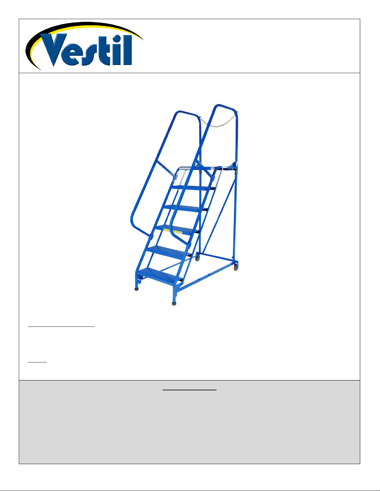
LAD-MM Series Mobile Ladder Stands
Instruction Manual
Receiving instructions:
After delivery, remove the packaging from the product. Inspect the product closely to determine whether
it sustained damage during transport. If damage is discovered, record a complete description of it on the
bill of lading. If the product is undamaged, discard the packaging.
NOTE:
The end-user is solely responsible for confirming that product design, installation, use, and maintenance
comply with laws, regulations, codes, and mandatory standards applied where the product is used.
Table of Contents
Specifications by Model…………………….………………………………………………………………………..…. 2
Signal Words………….……................................................................................................................................ 3
Hazards of Improper Use……………………………………………………………………………………………….. 3
Exploded Parts Diagrams and Bills of Materials…..……………………………………………………………...4 – 8
Assembly Instructions………………………………………………………………………………………………9 – 11
Use Instructions…………………..…………………………………………………………………………………….. 11
Inspections & Maintenance…………................................................................................................................. 12
Labeling Diagram………...…............................................................................................................................. 12
Limited Warranty…………...…………………………………………………………………………………………… 13
Copyright 2017 Vestil Manufacturing Co. Page 1 of 13
Page 2
Rev. 11.8.2017 LAD-MM, MANUAL
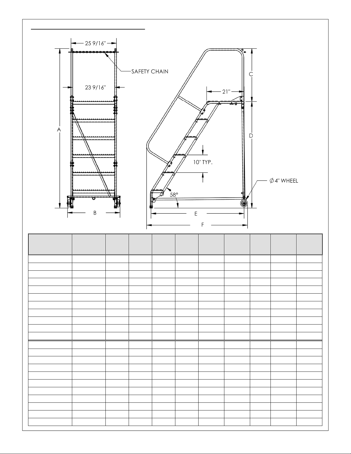
Product Specifications by Model:
Dimensions and other relevant specifications for each FHS-series crane appear in the table below.
Model
LAD-MM-2-P 2 50” 291/2” 30” 20” 271/4” 381/2” 58° 350 lb. 69 lb.
LAD-MM-3-P 3 60” 291/2” 30” 30” 331/2” 387/16” 58° 350 lb. 82 lb.
LAD-MM-4-P 4 70” 291/2” 30” 40” 393/4” 425/8” 58° 350 lb. 100 lb.
LAD-MM-5-P 5 80” 291/2” 30” 50” 46” 493/4” 58° 350 lb. 119 lb.
LAD-MM-6-P 6 90” 291/2” 30” 60” 521/4” 5611/16” 58° 350 lb. 135 lb.
LAD-MM-7-P 7 100” 291/2” 30” 70” 581/2” 623/8” 58° 350 lb. 150 lb.
LAD-MM-8-P 8 110” 291/2” 30” 80” 643/4” 685/8” 58° 350 lb. 169 lb.
LAD-MM-9-P 9 120” 291/2” 30” 90” 71” 747/8” 58° 350 lb. 185 lb.
LAD-MM-10-P 10 130” 291/2” 30” 100” 771/4” 811/8” 58° 350 lb. 202 lb.
LAD-MM-11-P 11 140” 32” 30” 110” 831/2” 873/8” 58° 350 lb. 222 lb.
LAD-MM-12-P 12 156” 32” 36” 120” 893/4” 931/4” 58° 350 lb. 247 lb.
LAD-MM-2-G 2 50” 291/2” 30” 20” 271/4” 381/2” 58° 350 lb. 70 lb.
LAD-MM-3-G 3 60” 291/2” 30” 30” 331/2” 381/2” 58° 350 lb. 84 lb.
LAD-MM-4-G 4 70” 291/2” 30” 40” 393/4” 435/8” 58° 350 lb. 101 lb.
LAD-MM-5-G 5 80” 291/2” 30” 50” 46” 493/4” 58° 350 lb. 121 lb.
LAD-MM-6-G 6 90” 291/2” 30” 60” 521/4” 5611/16” 58° 350 lb. 137 lb.
LAD-MM-7-G 7 100” 291/2” 30” 70” 581/2” 623/8” 58° 350 lb. 152 lb.
LAD-MM-8-G 8 110” 291/2” 30” 80” 643/4” 685/8” 58° 350 lb. 172 lb.
LAD-MM-9-G 9 120” 291/2” 30” 90” 71” 747/8” 58° 350 lb. 188 lb.
LAD-MM-10-G 10 130” 291/2” 30” 100” 771/4” 811/8” 58° 350 lb. 205 lb.
LAD-RF-11-G
LAD-RF-12-G 12 156” 32” 36” 120” 893/4” 931/4” 58° 350 lb. 250 lb.
Number of
steps
11
A:
Overall
height
140” 32” 30” 110” 831/2” 873/8”
B:
Overall
width
C:
Railing
height
D:
Platform
height
E:
Usable
length
F:
Overall
length
Step
slope
58°
Capacity
350 lb. 225 lb.
Net
Weight
Copyright 2017 Vestil Manufacturing Co. Page 2 of 13
Page 3
Rev. 11.8.2017 LAD-MM, MANUAL
Signal words:
This manual classifies personal injury risks and situations that could lead to property damage with SIGNAL WORDS.
These signal words announce an associated safety message. The reader must understand that the signal word chosen
indicates the seriousness of the described hazard.
Identifies a hazardous situation which, if not avoided, WILL result in DEATH or
Identifies a hazardous situation which, if not avoided, COULD result in DEATH or
Indicates a hazardous situation which, if not avoided, COULD result in MINOR or
Identifies practices likely to result in product/property damage, such as operation that might
SERIOUS INJURY. Use of this signal word is limited to the most extreme situations.
SERIOUS INJURY.
MODERATE injury.
damage the crane.
Hazards of Improper Use:
Vestil strives to identify all foreseeable hazards associated with the use of its ladders. However, no manual can
address every possible risk. The most effective means for avoiding injury is to apply sound judgment whenever using
this ladder. Read all of the instructions prior to using the ladder to familiarize yourself with assembly, use and
maintenance practices.
If this product is used improperly or carelessly, the user and/or bystanders might sustain serious personal
injuries or could even be killed. ALWAYS use the product properly:
Read and understand the entire manual before assembling, using or servicing the ladder.
DO NOT exceed the rated load of the ladder. The total weight applied to the ladder (weight of the user plus tools, etc.)
must not be greater than the rated load.
DO NOT use the ladder on uneven or unstable surfaces. ONLY use the ladder on level, even surfaces
Make sure that you will not contact overhead objects with either your body or with the ladder during use.
Always unload the ladder before leaving it unattended.
Remove foreign matter, like mud or grease, from your shoes before walking on the ladder.
ALWAYS face the stairs and use the handrails while ascending and descending the ladder.
DO NOT increase the height of the platform or of a step by standing on other objects placed on the ladder.
Inspect the ladder as described in “Inspections & Maintenance” on p. 12. DO NOT use the ladder unless it is in normal
condition. ONLY use manufacturer-approved replacement parts if repairs are necessary.
DO NOT use the ladder if the caps on the front legs are significantly worn (see exploded parts diagrams on p. 4-8).
Caps should prevent the ladder from sliding. If either or both caps are too worn to function properly, replace them
before using the ladder again.
ONLY use the ladder to access objects that you cannot otherwise reach. DO NOT use the ladder for any other
purpose. For instance, DO NOT use the ladder as a storage rack or as a way to move people or material. Always
unload the ladder before leaving it unattended.
DO NOT lean or reach over the sides of the ladder. Position the ladder as close to the work as possible.
DO NOT attempt to move the ladder while someone is using it.
DO NOT use the ladder to transport people or objects.
DO NOT remove or obscure any label. Each label must be readable, undamaged, and present in the appropriate
location (see “Labeling diagram” on p. 12).
DO NOT modify this ladder! Unauthorized modifications automatically void the limited warranty (see p. 13) and might
make the ladder unsafe to use.
This product must be properly maintained to function properly. (See “Inspections & Maintenance”, p. 12.)
Keep the ladder clean & dry.
Periodically check the ladder frame. The ladder should be solid, square, and free of rust and corrosion.
Lubricate the wheel bolts whenever necessary for the wheels to rotate freely.
The ladder stand is designed for both indoor and outdoor use. However, it should be stored indoors when not in use.
Copyright 2017 Vestil Manufacturing Co. Page 3 of 13
Page 4
Rev. 11.8.2017 LAD-MM, MANUAL
5
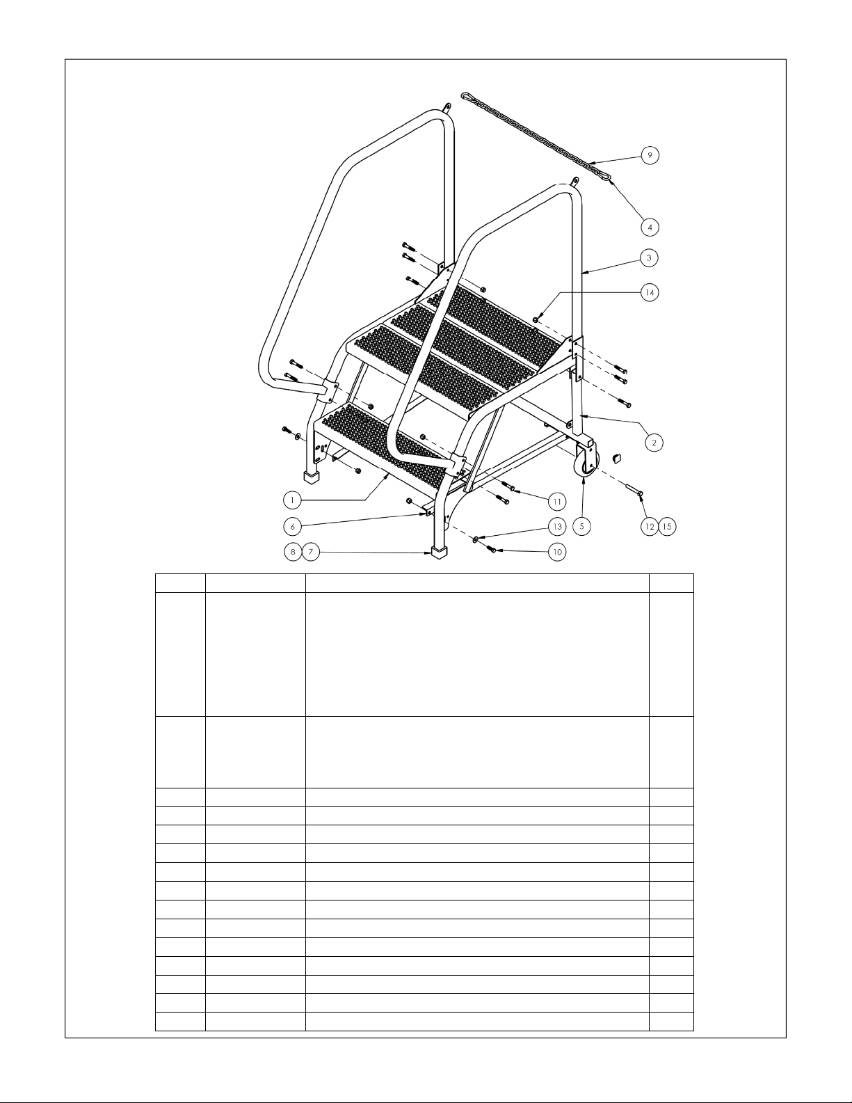
Exploded Parts Diagram and Bill of Materials:
LAD-MM-2-P & LAD-MM-2-G
LAD-MM-3-P & LAD-MM-3-G
LAD-MM-4-P & LAD-MM-4-G
*NOTE: Diagram shows LAD-MM-2-P.
Item Part no. Description Qty.
1
2
44-647-053
44-647-054
44-647-053
44-647-052
44-647-006
44-647-010
44-514-299
44-514-300
44-514-301
Weldment, step frame:
LAD-MM-2-P
LAD-MM-2-G
LAD-MM-3-P
LAD-MM-3-G
LAD-MM-4-P
LAD-MM-4-G
Weldment, back leg:
2-step, 26” step: LAD-MM-2-P & LAD-MM-2-G
3-step, 26” step: LAD-MM-3-P & LAD-MM-3-G
4-step, 26” step: LAD-MM-4-P & LAD-MM-4-G
3 44-524-059 Weldment, handrail 2
4 08-145-008 Snap hook, 1/4” 2
5 16-132-009 Wheel, PP-4/1.25-W 2
6 44-014-332 Frame, base support 2
7 99-024-027 Square cap, 1” x 1”, 60 Duro. 2
8 99-025-025 1” plastic plug 4
9 99-145-031 3/16” chain 24” 1
10 11055 Hex bolt, gr, A, zinc plated, 5/16”-18 x 1” 4
11 11060 Hex bolt, HHCS,
12 11113 Hex bolt, gr. A, plain finish, 3/8”-16 x 21/2” 2
13 33006 Flat washer, zinc plated, USS, 5/16” 4
14 37021 Nylon insert lock nut, gr. 2, zinc finish, 5/16”-18 14
15 37024 Nylon insert lock nut, gr. 2, zinc finish, 3/8”-16 2
1
1
1
1
1
1
1
1
1
/16”-18UNC x 13/4” 10
Copyright 2017 Vestil Manufacturing Co. Page 4 of 13
Page 5

Rev. 11.8.2017 LAD-MM, MANUAL
5
Exploded Parts Diagram & Bill of Materials:
LAD-MM-5-P & LAD-MM-5-G
LAD-MM-6-P & LAD-MM-6-G
LAD-MM-7-P & LAD-MM-7-G
*NOTE: Diagram shows LAD-MM-5-P.
Item Part no. Description Qty.
44-647-007
44-647-011
1
44-647-008
44-647-012
44-647-009
44-647-013
44-514-302
2
44-514-303
44-514-304
3 44-524-057 Weldment, handrail 2
4 08-145-008 Snap hook, 1/4” 2
5 16-132-009 Wheel, PP-4/1.25-W 2
6 44-014-320 Frame, base support 2
7 99-024-027 Square cap, 1” x 1”, 60 Duro. 2
8 99-025-025 1” plastic plug 4
9 99-145-031 3/16” chain 24” 1
10 11055 Hex bolt, gr, A, zinc plated, 5/16”-18 x 1” 4
11 11060 Hex bolt, HHCS,
12 11113 Hex bolt, gr. A, plain finish, 3/8”-16 x 21/2” 2
13 33006 Flat washer, zinc plated, USS, 5/16” 4
14 37021 Nylon insert lock nut, gr. 2, zinc finish, 5/16”-18 18
15 37024 Nylon insert lock nut, gr. 2, zinc finish, 3/8”-16 2
Weldment, step frame:
LAD-MM-5-P
LAD-MM-5-G
LAD-MM-6-P
LAD-MM-6-G
LAD-MM-7-P
LAD-MM-7-G
Weldment, back leg:
5-step, 26” step: LAD-MM-5-P & LAD-MM-5-G
6-step, 26” step: LAD-MM-6-P & LAD-MM-6-G
7-step, 26” step: LAD-MM-7-P & LAD-MM-7-G
1
1
1
1
1
1
1
1
1
/16”-18UNC x 13/4” 14
Copyright 2017 Vestil Manufacturing Co. Page 5 of 13
Page 6

Rev. 11.8.2017 LAD-MM, MANUAL
3
Exploded Parts Diagram & Bill of Materials:
LAD-MM-8-P & LAD-MM-8-G
LAD-MM-9-P & LAD-MM-9-G
LAD-MM-10-P & LAD-MM-10-G
*NOTE: Diagram shows LAD-MM-8-P.
Item Part no. Description Qty. Item Part no. Description Qty.
7 99-024-027
8 99-025-025 1” plastic plug 4
9 99-145-031
10 11055
11 11060
12 11113
13 33006
1
2
44-647-061
44-647-060
44-647-063
44-647-062
44-647-065
44-647-064
44-514-305
44-514-306
44-514-307
Weldment, step frame:
LAD-MM-8-P
LAD-MM-8-G
LAD-MM-9-P
LAD-MM-9-G
LAD-MM-10-P
LAD-MM-10-G
Weldment, back leg:
LAD-MM-8-P & -G
LAD-MM-9-P & -G
LAD-MM-10-P & -G
1
1
1
1
1
1
1
1
1
3 44-524-082 Weldment, handrail 2
4 08-145-008 Snap hook, 1/4” 2
14 37021
5 16-132-009 Wheel, PP-4/1.25-W 2
6 44-014-400 Frame, base support 2
Copyright 2017 Vestil Manufacturing Co. Page 6 of 13
15 37024
Square cap, 1” x 1”,
60 Duro.
/16” chain 24” 1
Hex bolt, gr, A, zinc
plated,
Hex bolt, HHCS,
5
/16”-18UNC x 13/4”
Hex bolt, gr. A, plain
finish,
Flat washer, zinc
plated, USS,
Nylon insert lock nut,
gr. 2, zinc finish,
5
/16”-18 x 1”
3
/8”-16 x 21/2”
5
/16”
5
/16”18
Nylon insert lock nut,
gr. 2, zinc finish,
3
/8”16
2
4
18
2
4
22
2
Page 7

Rev. 11.8.2017 LAD-MM, MANUAL
3
LAD-MM-11-P & LAD-MM-11-G Exploded Parts Diagram & Bill of Materials
Item Part no. Description Qty. Item Part no. Description Qty.
Weldment, 11-step frame:
1 44-647-067
44-647-066
2 44-514-308
3 44-514-310
4 44-514-311
5 44-524-085
6 16-132-009
7 08-145-008
8 44-014-403
Copyright 2017 Vestil Manufacturing Co. Page 7 of 13
LAD-MM-11-P
LAD-MM-11-G
Weldment, back leg, 11step, 26” step
Assembly, outrigger, right 1
Assembly, outrigger, left 1
Weldment, handrail 2
Wheel, PP-4/1.25-W 2
Snap hook, 1/4” 2
Frame, base support 2
9 99-024-027
1
1
10 99-025-025
1
11 99-145-031
12 11055
13 11060
14 11113
15 33006
16 37021
17 37024
Square cap, 1” x 1”, 60
Duro.
2
1” plastic plug 4
/16” chain 24” 1
Hex bolt, gr, A, zinc plated,
5
/16”-18 x 1”
Hex bolt, HHCS, 5/16”18UNC x 1
Hex bolt, gr. A, plain finish,
3
/8”-16 x 21/2”
Flat washer, zinc plated,
USS,
Nylon insert lock nut, gr. 2,
zinc finish,
Nylon insert lock nut, gr. 2,
zinc finish,
5
/16”
3
/4”
5
/16”-18
3
/8”-16
4
18
2
4
22
2
Page 8

Rev. 11.8.2017 LAD-MM, MANUAL
3
LAD-MM-12-P & LAD-MM-12-G Exploded Parts Diagram & Bill of Materials
Item Part no. Description Qty. Item Part no. Description Qty.
Weldment, 12-step frame:
1 44-647-069
44-647-068
2 44-514-309
3 44-514-310
4 44-514-311
5 44-524-086
6 16-132-009
7 08-145-008
8 44-014-404
Copyright 2017 Vestil Manufacturing Co. Page 8 of 13
LAD-MM-12-P
LAD-MM-12-G
Weldment, back leg, 12step, 26” step
Assembly, outrigger, right 1
Assembly, outrigger, left 1
Weldment, handrail 2
Wheel, PP-4/1.25-W 2
Snap hook, 1/4” 4
Frame, base support 2
9 99-024-027
1
1
10 99-025-025
1
11 99-145-031
12 11055
13 11060
14 11113
15 33006
16 37021
17 37024
Square cap, 1” x 1”, 60
Duro.
1” plastic plug 4
/16” chain 24” 2
Hex bolt, gr, A, zinc plated,
5
/16”-18 x 1”
Hex bolt, HHCS, 5/16”18UNC x 1
Hex bolt, gr. A, plain finish,
3
/8”-16 x 21/2”
Flat washer, zinc plated,
USS,
Nylon insert lock nut, gr. 2,
zinc finish,
Nylon insert lock nut, gr. 2,
zinc finish,
5
/16”
3
/4”
5
/16”-18
3
/8”-16
2
4
18
2
4
22
2
Page 9

Rev. 11.8.2017 LAD-MM, MANUAL
5
+
Assembly Instructions:
Improper assembly might make the ladder unsafe to use.
Visually inspect all ladder components prior to assembly. Look at each part of the ladder immediately after you
receive the package from the shipper. Look for damage that might have occurred during shipping. DO NOT assemble
or use the ladder stand if you notice any damage to one or more of the steps or to any other structural element (step
weldment, back leg weldment, base supports, and handrails) of the ladder. Using the ladder stand despite weakness of
a frame member could result in serious personal injuries.
DO NOT assemble the ladder by yourself. At least 2 people are needed for assembly.
Read the entire instruction manual before assembling this ladder.
DO NOT use the ladder if a wheel is damaged. Damaged wheels might cause the ladder to wobble or tip when used.
The following tools are necessary to assemble the ladder:
1. 2 crescent wrenches (
2. Rubber mallet
NOTE: Numbers in the diagrams and in parentheses () correspond to part numbers in the exploded views on
pages 4-14.
Step 1: Fasten the back leg weldment to the stair frame weldment with 5/
back leg weldment as shown below (support tabs should face inwards).
Stair frame
weldment
Step 2: Fasten the base supports to the support brackets and wheel brackets with
Ladder
assembly
Support
bracket
Support
tab
5
/16” and 3/8”)
+
Base
support
Wheel
bracket
Back leg
weldment
in. hardware. Be sure to orient the
16
37021
/16in. – 18 hardware as shown below.
37021
11055 & 33006
33006 11055
37021
Wall
11060
Copyright 2017 Vestil Manufacturing Co. Page 9 of 13
Page 10

Rev. 11.8.2017 LAD-MM, MANUAL
Step 3: Install the plugs, caps, and wheels.
a) Install the plastic plugs and square caps in the leg tubes. First, press the 1in. plastic plug into the leg tubes.
Then, press the square caps over the plugs and onto the ends of the legs. If necessary, use a rubber mallet to
gently tap the plugs and caps into place.
b) Press a plug into each end of the cross brace.
c) Then, insert the wheels into the wheel brackets and install
axle. Periodically lubricate the bolts to allow the wheels to rotate freely.
3
/8”-16 x 21/2” bolts (11113). Secure the bolts with
Ladder
assembly
Cross
brace
Insert
plug
37024
16-132-009
1in. x 1in.
square cap
1in. black
plastic plug
Step 4 (LAD-MM-11 & LAD-MM-12 only): Install the outriggers. Unfasten the bolt (11055), flat washer (33006),
and lock nut (37021). Then, reinstall the hardware the outrigger, support bracket, and base support as shown.
44-514-311
Left outrigger
Support
bracket
Base
support
37021
44-514-310
Right outrigger
33006
11055
11113
Copyright 2017 Vestil Manufacturing Co. Page 10 of 13
Page 11

Rev. 11.8.2017 LAD-MM, MANUAL
Handrail
11060
37021
Step 5: Attach the handrails.
Step 6: Install the platform chain. Attach the snap hooks to the hook brackets.
Chain
Snap
hook
Hook
bracket
Side rail
Using the ladder:
Before climbing the ladder, stand on the bottom step and confirm that the caps solidly contact the ground. The
caps should prevent the front end of the ladder from moving.
To move the ladder, grasp either the handrails or the side rails and lift the front of the ladder. Ladders with more
steps are heavier and therefore require more effort to move. Only attempt to move the ladder if you are able to
comfortably lift it and can easily control it while balanced on its wheels.
Face the ladder and grasp the handrails while ascending or descending the steps. Do not lean against the
handrails or the platform chain.
Copyright 2017 Vestil Manufacturing Co. Page 11 of 13
Page 12

Rev. 11.8.2017 LAD-MM, MANUAL
A B C D
Inspections & Maintenance:
After assembling the ladder and before putting it into use, visually inspect the ladder. Make a written record that
describes the condition and appearance of the steps, handrails, wheels, (leg) caps, base supports, back leg
weldment, platform chain, and fasteners (bolts, nuts, etc.). This record establishes “normal condition” of the ladder.
When conducting subsequent inspections, compare your observations to the written record to determine whether the
ladder is in normal condition. Do not use the ladder unless it is in normal condition.
Regular inspections — at least once per month inspect the following items. Replace all parts that are damaged
before using the ladder again. DO NOT continue to use the ladder if damage cannot be repaired.
Handrails, snap hooks, and platform chains: Inspect both handrails. Confirm that they are solidly fastened to
the step weldment. Each handrail should be rigid and undamaged. Examine the platform chain and snap
hooks. Confirm that they are securely fastened to the handrails and are in normal condition.
Back leg weldment and wheels: Make sure that the back leg weldment is not bent, that the wheels are not
severely worn, that they are vertical (not angled towards or away from the ladder) and roll smoothly. Examine
the wheel brackets and hardware for damage. Tighten nuts and bolts, if necessary.
Frame members (step weldment, back leg weldment, base supports, handrails) and all fasteners (bolts, nuts,
pins): Inspect each frame member for damage like excessive wear, bends, and cracks. All frame pieces should
be square, rigid, and free of rust and corrosion. Remove rust with steel wool or a metal bristle brush and apply
touch-up paint to the affected area. Check the areas where frame members are bolted together. Check the
areas around bolt holes for cracks, elongated bolt holes, etc
Square (rubber) caps: Check the caps for cracks and excessive or uneven wear. Install replacement caps
before returning the ladder to service.
Outriggers (11 and 12 step models): Examine the outriggers. Both should be securely fastened to the step
weldment. Both outriggers should make solid contact with the ground, i.e. the ladder should not be able to
Maintenance: in addition to correcting issues discovered during inspections, maintain the ladder as
described below.
wobble. Confirm that the caps on the outrigger legs are in satisfactory condition.
Clean the ladder to remove dirt and grime, especially from step surfaces.
Lubricate bolts as necessary for the wheels to rotate freely.
Apply touchup paint wherever the finish is damaged.
Labeling diagram:
The ladder should be labeled as shown in the diagram (below). Replace any label that is damaged, missing, or not
easily readable (e.g. faded). DO NOT use the ladder unless all labels are in place and in normal condition.
A: Label 740 (on nosing of a step or platform)
B: Label 729A (on
nosing of a step)
D: Label 821 (on nosing of a step)
Copyright 2017 Vestil Manufacturing Co. Page 12 of 13
C: Label 287 ( on nosing of a step)
Page 13

Rev. 11.8.2017 LAD-MM, MANUAL
LIMITED WARRANTY
Vestil Manufacturing Corporation (“Vestil”) warrants this Semi-Automatic Strapping Machine, model S-2001 to be free
of defects in material and workmanship during the warranty period. Our warranty obligation is to provide a
replacement for a defective original part if the part is covered by the warranty, after we receive a proper request from
the warrantee (you) for warranty service.
Who may request service?
Only a warrantee may request service. You are a warrantee if you purchased the product from Vestil or from an
authorized distributor AND Vestil has been fully paid.
What is an “original part”?
An original part is a part used to make the product as shipped to the warrantee.
What is a “proper request”?
A request for warranty service is proper if Vestil receives: 1) a photocopy of the Customer Invoice that displays the
shipping date; AND 2) a written request for warranty service including your name and phone number. Send requests
by any of the following methods:
Mail Fax Email
Vestil Manufacturing Corporation (260) 665-1339 sales@vestil.com
2999 North Wayne Street, PO Box 507 Phone
Angola, IN 46703 (260) 665-7586
In the written request, list the parts believed to be defective and include the address where replacements should be
delivered.
What is covered under the warranty?
After Vestil receives your request for warranty service, an authorized representative will contact you to determine
whether your claim is covered by the warranty. Before providing warranty service, Vestil may require you to send the
entire product, or just the defective part or parts, to its facility in Angola, IN. The warranty covers defects in the
following original dynamic components: motors, hydraulic pumps, electronic controllers, switches and cylinders. It
also covers defects in original parts that wear under normal usage conditions (“wearing parts”), such as bearings,
hoses, wheels, seals, brushes, and batteries.
How long is the warranty period?
The warranty period for original dynamic components is 90 days. For wearing parts, the warranty period is 90 days.
The warranty periods begin on the date when Vestil ships the product to the warrantee. If the product was purchased
from an authorized distributor, the periods begin when the distributor ships the product. Vestil may, at its sole
discretion, extend the warranty periods for products shipped from authorized distributors by up to 30 days to account
for shipping time.
If a defective part is covered by the warranty, what will Vestil do to correct the problem?
Vestil will provide an appropriate replacement for any covered part. An authorized representative of Vestil will contact
you to discuss your claim.
What is not covered by the warranty?
1. Labor;
2. Freight;
3. Occurrence of any of the following, which automatically voids the warranty:
Product misuse;
Negligent operation or repair;
Corrosion or use in corrosive conditions;
Inadequate or improper maintenance;
Damage sustained during shipping;
Accidents involving the product;
Unauthorized modifications: DO NOT modify the product IN ANY WAY without first receiving
written authorization from Vestil. Modification(s) might make the product unsafe to use or might
cause excessive and/or abnormal wear.
Do any other warranties apply to the product?
Vestil Manufacturing Corp. makes no other express warranties. All implied warranties are disclaimed to the extent
allowed by law. Any implied warranty not disclaimed is limited in scope to t
Copyright 2017 Vestil Manufacturing Co. Page 13 of 13
 Loading...