

Page 1
INSTRUCTION MANUAL
MOBILE LADDER STAND
LAD-MM
MODEL NO. ________________________
SERIAL NO. ________________________
VESTIL MANUFACTURING CORP.
2999 NORTH WAYNE STREET, P.O. BOX 507, ANGOLA, IN 46703
TELEPHONE: (260) 665-7586 -OR- TOLL FREE (800) 348-0868
FAX: (260) 665-1339
URL: WWW.VESTILMFG.COM EMAIL: SALES@VESTIL.COM
Page 2
We produce several models of ladder stand so that our customers may select a product
that satisfies specific requirements. The products identified on the front page conform to
universal performance specifications disclosed in this manual, and each model fulfills our
demanding standards for quality, safety and durability.
SAFETY PRINCIPLES
Vestil Manufacturing Corp. recognizes the critical importance of workplace
safety. Each person who might participate in the assembly, use, operation, or
maintenance of the product must read this manual. Read the entire manual and fully
understand the directions BEFORE assembling, using or maintaining the ladder
stand. If you do not understand an instruction, contact Vestil for clarification.
Failure to adhere to the directions in this manual may result in serious personal
injury or even death.
Vestil is not liable for any injury or property damage that occurs as a
consequence of failing to apply the safe operation and maintenance procedures
explained in this manual or that appear on safety warning labels affixed to the product.
Failure to exercise good judgment and common sense may result in property damage,
serious personal injury, or death, and are not the responsibility of Vestil.
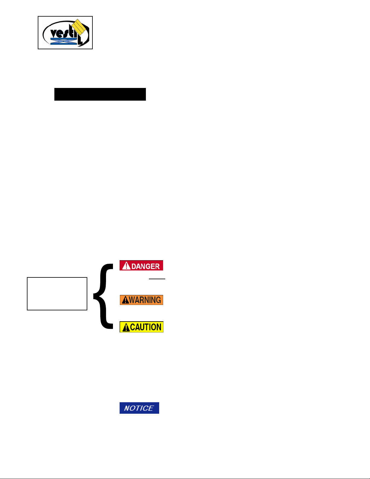
This manual applies the hazard identification methods suggested for instruction
manuals by the American National Standards Institute (ANSI) in ANSI standard Z535.6-
2006. In accordance with ANSI guidelines for hazard warning language, this manual
identifies personal injury risks and situations that could lead to property damage with
SIGNAL WORDS. These signal words announce an associated safety message. The
reader must understand that the signal word chosen to identify a particular safety hazard
categorizes the seriousness of that hazard according to the following convention:
These symbols
identify hazards
that may result in
personal injury
Identifies a hazardous situation which, if not
avoided, WILL
result in DEATH or SERIOUS INJURY. Use of
this signal word is limited to the most extreme situations.
Identifies a hazardous situation which, if not
avoided, COULD result in DEATH or SERIOUS INJURY.
Indicates a hazardous situation which, if not
avoided, COULD result in MINOR or MODERATE injury.
Although Z535.6-2006 approves the use of “CAUTION” without an
accompanying safety alert symbol (black equilateral triangle with
yellow exclamation point) as an alternative to “NOTICE”, this
manual differentiates between hazards that pose a risk of
personal injury and those that create mere property damage
situations. CAUTION appears exclusively in conjunction with
the safety alert symbol to identify injury risks.
Identifies practices not related to personal injury,
such as operation that could damage the table. No safety alert
symbol (equilateral triangle enclosing an exclamation point)
accompanies this signal word.
- 2 -
Page 3

TABLE OF CONTENTS
Safety Principles 2
Product Introduction 4
Safety Guidelines 5
Receipt & Assembly Instructions 7 -12
Safety Warning Messages 7
LAD-MM Parts List 8
Proper Use Procedure 12 -14
Safety Warning Messages 12 -13
Maintenance 14-15
Monthly Inspection Safety Checklist 15
Product Warranty and Service Agreement 17
TABLE OF FIGURES
LAD-MM MODELS
FIG. 1: Fully Assembled MM Labeled Picture 6
FIG. 2: Ladder Step Surfaces 7
FIG. 3: Safety Warning Label Diagram 16
- 3 -
Page 4

PRODUCT INTRODUCTION
MM and RF model ladder stands are rollable, meaning that they have only 2
wheels, as shown on the front cover. You can reposition the ladder by first lifting the
front legs off of the ground and then rolling it to the desired location. In contrast, a
rolling ladder has at least 1 castor or wheel located at each corner of the base. This
arrangement allows a person to reposition the ladder without having to lift the front
legs off of the ground.
We produce 2 kinds of rollable mobile ladder stand in order to satisfy a broad
spectrum of applications. The MM models feature larger elevated platforms and
smaller wheels than the RF variant. However, RF ladders are also collapsible,
which reduces the amount of space necessary for storage. Notice that although
collapsible, RF ladders do not fold. Folding ladders do not require any degree of
disassembly in order to reduce to smaller configurations.
The number and surface texture of the steps are also variable. “P” variety steps
have raised, circular perforations, while “G” variants have elongated perforations
with serrated edges. Additionally, RF-EZ ladders have a reduced step slope (50º as
opposed to the standard 58º) for less strenuous climbing.
Vestil Manufacturing Corp. created this Instruction Manual to acquaint owners
and users of our rolling ladder stands with safety procedures. The manual includes
directions for proper usage and routine maintenance of your ladder stand.
According to ANSI standard A14.7-2006, section 6.15, employers are
responsible for instructing employees in the proper use of the product.
Therefore, employees and any other persons, who may foreseeably use,
operate, install or perform maintenance on the ladder stand, must read and
understand the instructions before the employer may allow employees to use
the ladder. Employees should have access to the manual at all times.
Personnel should consult the directions before each use. Although Vestil strives to
identify all hazardous situations that could arise during the use of its products, this
manual cannot address every conceivable danger. The user is responsible for
exercising sound judgment at all times.
Read and understand the information contained in the manual before you
use or perform maintenance on the ladder stand. Contact Vestil for answers
to all questions that you have after reading the manual.
The limited warranty that covers the product appears on the final page of this
manual. Vestil Manufacturing Corp. specifically excludes all other warranties,
express or implied, including but not limited to, implied warranties of fitness for a
particular purpose and any implied warranties of merchantability.
Thank you for purchasing a mobile ladder stand made by Vestil
Manufacturing Corporation (“Vestil”). We design each ladder to
combine solid construction with mobility. Our ladders are
durable, high-quality products that require minimal maintenance.
- 4 -
Page 5
SAFETY GUIDELINES
Read the entire manual before you assemble the ladder stand or use it for the first time; refer to it
for manufacturer-approved safe maintenance procedures (p. 14). If questions remain after reading the
manual, contact Vestil for answers. DO NOT attempt to resolve any problems with the ladder stand
unless you are certain 1) that you can do so without risk to yourself and others, AND 2) that the ladder
will be safe to use afterwards. DO NOT modify the product in any manner without the express, written
approval of Vestil.
The information contained in this manual will prepare the user to safely use the ladder stand. Familiarity
with all of the product’s attributes is necessary BEFORE assembling, using, or performing maintenance on
the ladder stand.
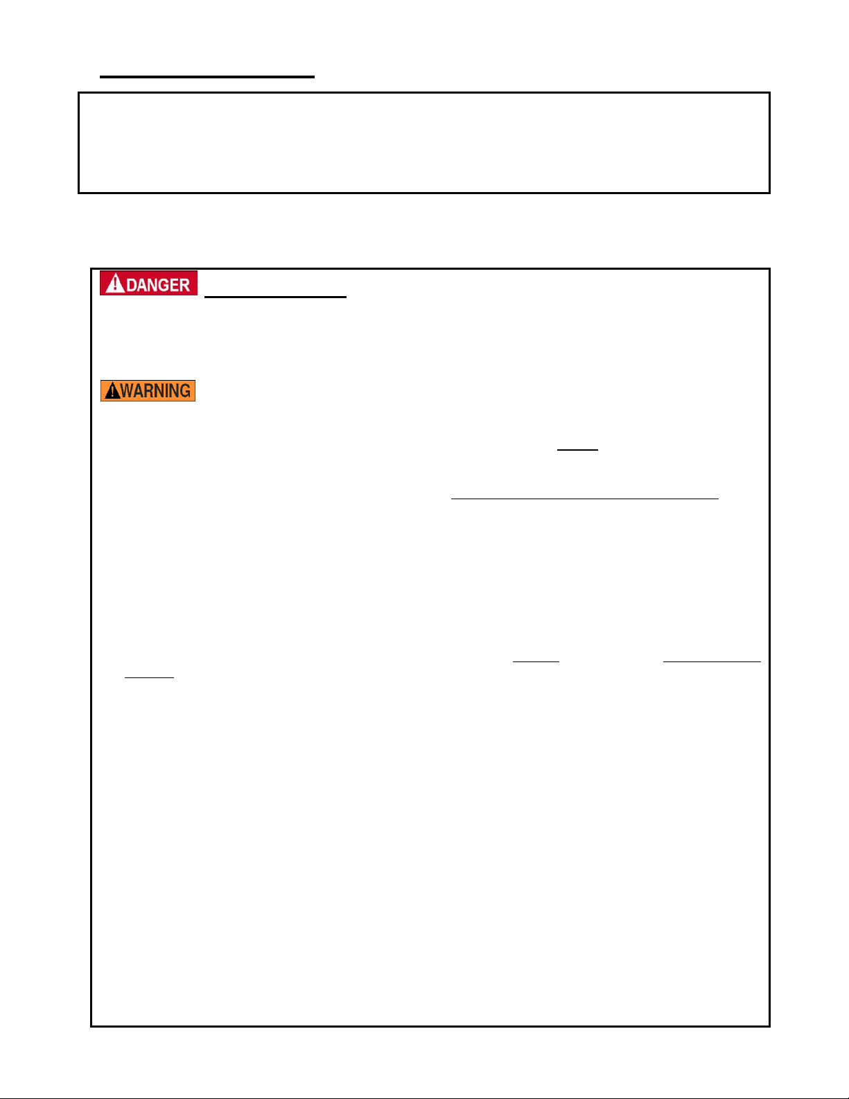
Electrocution Risks:
• DO NOT contact live electrical wires with any part of the ladder! Do not pass beneath electrical
wires with the ladder unless power to the wires is turned off AND you are certain that no contact
between the wires and the ladder will occur.
• DO NOT use, assemble, or move the ladder beneath or close to electrical wires; move the ladder
to a safe location first.
• DO NOT exceed the ladder stands 350 pound overall load rating (see FIG. 3 on p. 15). This means
that the total weight present on the ladder (personnel + material) cannot exceed 350 pounds.
• DO NOT modify the ladder in any manner without first obtaining written authorization from Vestil.
Modification may weaken the ladder.
• DO NOT use the ladder on uneven, damaged or unstable surfaces, or on surfaces contaminated with
slippery substances like oil, grease, water, ice, etc. Safe use requires a solid and level surface that is
able to support the ladder stand while loaded to capacity.
• DO NOT lean or reach over the handrails; DO NOT rock the ladder from side to side. Reposition the
ladder if you cannot reach the object you want.
• Clear all debris, including liquids, from the path of travel if you have to reposition the ladder. If
moisture is present around the base of the ladder or along the path of travel, absorb the liquid before
moving or using the ladder.
• Make sure that you will not contact overhead objects with your body or with the ladder during use or
while rolling the ladder stand to a new location.
• ONLY use the ladder to access objects that you cannot otherwise reach. DO NOT use the ladder for
any other purpose. For example, DO NOT use the ladder as storage, or as a way to move people or
material. Always unload the ladder before leaving it unattended..
• Verify the placement and legibility of all safety warning labels as shown in FIG. 3 on p. 15. If any labels
become damaged or unreadable, contact Vestil for replacement(s).
• Remove foreign matter, like mud or grease, from your shoes before stepping onto the ladder.
• ALWAYS use the handrails while ascending and descen ding the ladder.
• ONLY stand on the steps or the platform.
• DO NOT increase the height of the platform or of any individual step by adding an extension to the
ladder or by placing any other object on the ladder.
• DO NOT use a ladder stand that has been damaged or weakened from any cause until repairs are
complete. DO NOT climb a ladder or stand on a platform that has sustained damage. Destroy any
ladder that is damaged or worn beyond repair.
• Inspect the ladder immediately upon receipt. Look for evidence that the ladder was damaged during
shipping.
• Inspect the fasteners and structural elements BEFORE each use for damage, such as: unusual wear,
deterioration, corrosion, and warping. Tighten all loose fasteners (bolts, nuts) that are in good
condition; contact Vestil for replacement parts as necessary.
• DO NOT use the ladder in front of a door, UNLESS the door is secured 1) in an open position, 2) is
locked, and 3) is either attended or barricaded.
• DO NOT step onto or off of the ladder from any other elevated surface UNTIL the ladder is immobilized.
• Face the steps when ascending or descending the steps. This means that you should back down the
steps and use the handrails. However, RF-EZ models have a step slope of 50 degrees and may be
descended by walking forward down the steps.
- 5 -
Page 6
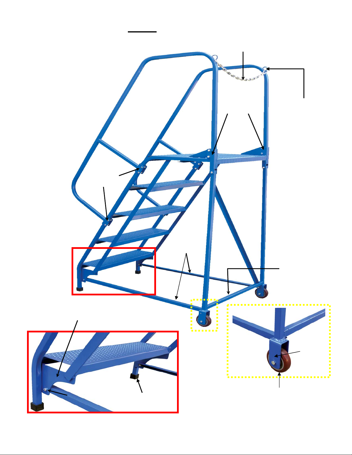
FIG. 1: LAD-MM
p
Handrail
2ft. safety chain
Handrail
Brackets
Base
supports
Handrail
Brackets
Angled
Support
1 inch D-ring
Back Leg
Back Leg
Horizontal
Support
Stair Frame Bracket
Step
5/16 inch nylon
lock nut
Rubber Ca
- 6 -
4 inch hard
rubber wheels (2)
Wheel
Bracket
Page 7

FIG. 2: LADDER STEP SURFACES
P (Perforated) G (Grip-Strut)
RECEIPT & ASSEMBLY INSTRUCTIONS
You should visually inspect the ladder prior to assembly and use. Look at each part of
the ladder immediately after you receive the package from the shipper. Look for damage that might have
occurred during shipping. If damage is present, contact Vestil; DO NOT assemble or use the ladder
stand if you notice any damage to one or more of the steps or to any other structural element (step
weldment, back leg weldment, horizontal braces) of the ladder. Using the ladder stand despite weakness
of a structural component could cause the ladder to collapse and result in serious personal injuries. DO
NOT use your ladder stand if any of the hardware (bolts, nuts, etc.) is damaged. Contact Vestil to order
replacement parts. Additionally,
• DO NOT assemble the ladder by yourself. At least 2 persons are needed for assembly. Do not
participate in the assembly process if you have weight-lifting restrictions, back injuries or other
physical conditions that could make lifting the ladder dangerous.
• Review the safety guidelines on p. 5 before you attempt to assemble the ladder.
• Read the entire instruction manual before assembling the ladder stand; only assemble the ladder
stand if you fully understand the associated risks and the manufacturer-approved assembly
procedure discussed below.
• DO NOT assemble the ladder stand unless your employer has given you approval to do so.
• DO NOT deviate from the assembly instructions. To be safe for use, the product must be
assembled as directed.
• DO NOT modify the ladder stand in any way unless and until you receive written approval from
Vestil.
• DO NOT use the ladder stand if either of the wheels is damaged. A damaged wheel may cause the
ladder stand to tip over while supporting personnel and/or material.
• ALWAYS use proper lifting techniques to minimize back strain if you must pick up ladder parts or
move the ladder.
• Any unauthorized modification automatically voids the limited warranty. Contact Vestil to order
replacement parts.
• The ladder stand is designed for both indoor and outdoor use. However, the ladder stand should
be sheltered from the weather when not in use.
After accepting delivery of a new ladder stand, remove it from the packaging and confirm that all parts
are present and undamaged. Do not assemble the ladder if any of the components is damaged.
Compare the parts to the photographs and tabular data below; contact Vestil if the ladder as delivered
is incomplete or damaged.
The following tools are necessary to assemble the ladder:
1. 2 crescent wrenches (1/2in. or adjustable to 1/2in.);
2. Rubber mallet;
3. Proper work clothing, eye protection, gloves.
- 7 -
Page 8

1
2
LAD-MM Parts List
2
3
A
(actual size)
B
(actual size)
G
Structural Elements
Hardware
Package
C
(actual size)
D
E
(actual size)
I
Id
Symbol
H
Replacement
Part No.
Quantity Description
1 44-647-014 1 Step Frame Weldment
2 44-514-184 1 Back Leg Weldment
3 44-014-233 2 Horizontal Braces
4 44-524-038 2 Hand Rail Weldment
A 11059 10 5/16” - 18 x 1-1/2” Bolt
B 11053 2 5/16” – 18 x ¾” Bolts
C 37021 16 5/16” – 18 Nylon Lock Nuts
D 11062 4 5/16” – 18 x 2-1/4” Bolts
E 44-145-004 1 2ft. chain
F 0500499 2 Spring Hooks
G 16-132-009 2 4” X 1-1/4” wheels
H 0383-0000-2601
2 1” x 1” Square Cap
I SQR-1-14-20 2 1” Plastic Plugs
F
- 8 -
Page 9

3
3
Instruction 1: Install a plastic plug (I) into each front leg of the step weldment (1) as shown in the
photographs below. The front legs are circled in the first picture.
1 2
Stair frame
bracket
Instruction 2: Slide a square cap (H) over each front leg. The caps should slide easily, but you may
use a rubber mallet to tap the caps firmly into place if necessary.
Do not damage the plugs or the caps. Plugs prevent the front legs from penetrating
through the caps when weight is applied to the ladder. Similarly, the caps prevent the ladder from
sliding. Damaged caps and or plugs could make the ladder unsafe to use.
1 2
Instruction 3: Attach each of the 4in. wheels (G) to the wheel brackets of the back leg weldment (2)
with a 2-1/4in. bolt (D). The wheel brackets are circled in the first picture. Install each bolt so that
the threaded end protrudes from the inside edge of the bracket. Connect a 5/16in. lock nut to the
threaded end of each bolt. Tighten the connection with a 5/16in. crescent wrench. Try to spin the
wheels with your hands. If the wheels do not rotate freely, loosen the nut slightly.
1
2
Outside Edge
Inside Edge
Outside
Outside Edge
Inside
2-1/4inch Bolt
- 9 -
Page 10

4
Outside Edge
2-1/4inch Bolt
Inside Edge
5/16in.
Lock Nut
Instruction 4: Attach the step weldment (1) to the back leg weldment (2) with 1-1/2in. bolts. Position
the steps face down so that the free end of the platform projects upwards from the ground.
2
1
Platform
5/16in.
Lock Nut
-
Instruction 5: Rotate the ladder so that either the left or right side rests on the ground. Connect a
horizontal brace (3) to the side of the back leg weldment (2) in contact with the ground, using a 2-1/4in. bolt
(D) and a 5/16in. lock nut. Tighten a nut onto the bolt with your fingers. Use 5/16in. crescent wrenches to
tighten the connection, but leave enough play in the connection to later connect the opposite end of the
base support to the stair frame bracket
2
2-1/4in. Bolt
1
Base Support
- 10 -
Page 11

Base Support
3
4
5/16in.
Lock Nut
Instruction 6: Connect the other end of the base support to the step frame bracket with a 3/4in. bolt (B).
Tighten a 5/16in. nut onto the bolt with your fingers. Tighten the connection slightly with a wrench.
5/16in. Lock Nut
Instruction 7: Repeat steps 5 and 6 with the remaining base support.
Instruction 8: Rotate the ladder onto the wheels and front legs in the manner shown.
DO NOT lift the ladder until all other persons clear the area. If you are uncertain that you
can control the ladder as it rotates, enlist a coworker to help you. If you are under weight-lifting
restrictions DO NOT perform instruction 8; get someone else to rotate the ladder.
Instruction 9: Tighten all connections with crescent wrenches. Use one wrench to prevent the hex head of
a bolt from rotating. Turn the nut with a second wrench until the connection is tight.
Instruction 10: Attach the handrail weldments (4) to the step weldment (1) as demonstrated below. Use
two 1-1/2in. bolts and two 5/16in. lock nuts to secure each bracket to the step weldment. To connect each
handrail, first insert the leg portion into the platform brackets; then slide the integral handrail brackets into
place. In the photos, the leg of a handrail and the receiving bracket on the platform are circled and solid
squares identify the integral brackets. Feed the bolts through the corresponding holes so that the threaded
end of each bolt protrudes through the inner portion of each bracket.
DO NOT stand on the ladder to install the handrails! Connect both handrails to the step
weldment from the ground; then fully tighten all hardware/fasteners.
1 2
- 11 -
Outer surface of bracket
Page 12

4
5 3
5/16in. Lock Nut
6
7
1-1/2in. Bolt
Inner edge of platform
handrail bracket
Inner edge
Instruction 11: Install the safety chain. Attach the spring hooks (F) to the end links of the safety
chain (E). Next, attach the spring hooks to the D-rings of the handrail weldments.
Proper Use:
Review the safety guidelines on p. 5 before each use. See 29 CFR
1910.26(c)(3)(viii) and 1910.333(c) for OSHA-recommended work practices to be used when work
is performed on or near electric circuits.
• To avoid electrocution, DO NOT contact electric wires with the ladder. The ladder is
made of steel, which is an excellent conductor of electricity.
• DO NOT use the ladder beneath or in the vicinity of electric wires. If your body
accidentally contacts the wires, electrocution could result.
- 12 -
Page 13

To avoid the potential for serious personal injury, always adhere to the following
3
practices:
• Ladders should not be used as a brace, skid, guy or gin pole, gangway, or for any other
unintended uses.
• Remove foreign material, such as mud or grease from the bottom of your shoes before
ascending the ladder.
• Always use the handrails while ascending or descending the ladder.
• Do not attempt to move the ladder, which requires lifting, if you are under any weight-lifting
restrictions.
The step slope is 58 degrees for all MM and RF mobile ladder stands except the
RF-EZ variant. Current regulatory standards recommend that persons face the steps while
ascending and descending the steps. This means that to descend the ladder you should back
down the steps, holding the handrails.
Although ladders are simple mechanisms, improper use can result in serious injuries. OSHA
regulation 1910.26(c)(2)(vi) requires immediate inspection if any of the following events occur:
• The ladder tips over: inspect ladder for dents or bends in the side rails, and for excessively
dented rungs; check all rung-to-siderail connections; check hardware connections; check rivets
for shear. 1910.26(c)(2)(vi)(a)
• Exposure to oil and/or grease: the ladder should be cleaned of oil, grease, or other slippery
materials. This can easily be done with a solvent or by steam cleaning the effected area.
1910.26(c)(2)(vi)(d).
Position the ladder on a dry, level, undamaged surface. The ladder should be close enough to
the object you need that you will not have to reach more than a few inches beyond the handrail to
retrieve it. A second person may stabilize the ladder by standing with one foot on the fist step
and keeping the other foot on the ground, and grasping both handrails.
1. Instruct everyone in the immediate area that you have to move the ladder. Make
sure that the path of travel is clear.
2. Using proper lifting technique, grasp the ladder by the handrail as shown on the
next page. Lifting the front legs off of the ground by grasping the siderail (photo
3) is not recommended. Be sure not to step beneath the front feet as you walk
the ladder to a new location. Step directly beneath the first step.
21
3. Set the ladder down once it is in position. Be certain that the ground beneath the
ladder is even, level, and dry. The wheels can be chocked to ensure that the
ladder is immobilized.
- 13 -
Page 14

4. Ascend the ladder by facing the steps and using both handrails. The ladder is
designed to support a combined weight of 350 pounds. Before lifting the item,
verify that your weight plus the weight of the item is no more than 350 pounds.
Retrieve the item.
5. Descend the ladder with the item. Use one handrail, and back down the steps
until your reach the ground. For RF-EZ model ladder stands, ANSI standard
A14.7, section 6.10 approves walking forwards down the step. Always use a
handrail while descending the steps.
6. When you are finished using the ladder, move it indoors
to a location that will not
present a hazard to ongoing activities. The ladder should always be stored
somewhere that provides protection from the weather.
Maintenance Procedures:
Proper maintenance is an essential responsibility of the ladder owner and end-
user. Failure to adopt and implement regular maintenance procedures could lead to serious
personal injuries and/or death.
We recommend that every owner/end-user perform regular inspections and maintenance on the
ladder.
1. Visual inspection after assembly and before each use: personnel who intend to use
the ladder MUST inspect it for signs of sustained damage. Sustained damage may
include unusual wear, deterioration, corrosion, broken welds.
2. General Maintenance:
• Cleaning
air from a leaf blower). To avoid rusting the components, we do not recommend
using water to clean the ladder.
• Lubrication
moved, it may be lubricated with spray lubrication according to the directions on the
spray can.
• Paint
ladder may be more susceptible to rust, which could eventually render the ladder
unsafe to use.
• Replace
o Labels: if any labels are damaged and/or unreadable, contact Vestil for a
o Wheels: squeeze the sides of the semi-pneumatic tires and press down on the
o Rubber caps: the bottom surface of the caps prevents the ladder from shifting
3. Directions for tightening and securing all threaded fasteners: All lock nuts should
rest snugly against the ladder. Connections should not be so tight that the ladder
deforms under either the bolt head or nut. Verify that each fastener is securely attached
: remove debris from the ladder using a broom and/or accelerated air (e.g.
: if the axle (in RF model ladder stands) makes noises when the ladder is
: the paint provides a degree of weather defense. If the paint is chipped, the
:
replacement. DO NOT use the ladder until you receive and affix the new
label(s) to the ladder according to the diagram of FIG. 3 on p. 17.
tread. If the wheels compress easily, they need to be replaced. DO NOT use
the ladder again until the replacement wheel has been installed.
1. To install a new wheel, review the “Safety Guidelines,” on p. 5, and the “To
Raise & Collapse the Ladder,” safety warning messages on p. 13.
2. Perform steps 1 through 8 of the “To Raise & Collapse the Ladder”
procedure on p. 13-14.
3. Turn the ladder onto the side that has a good wheel (good wheel side
should contact the ground). The defective wheel should be exposed.
4. Remove the cotter pin; then remove the wheel. Install the replacement
wheel according to Instruction 6 on p. 10.
while in use. If the bottom of either cap is worn so that it will not evenly contact
the ground it must be replaced. Contact Vestil to order replacement caps.
- 14 -
Page 15

by pulling on the bolt head and attempting to rotate the bolt. Tighten any loosened lock
nuts with a pair of 5/16in. crescent wrenches.
Employers should designate [a] person[s] to conduct monthly preventive
maintenance. Inspect each of the components identified below; if damage and/or deformation of any
component are/is present DO NOT use the ladder. Clearly indicate that the ladder is unusable, move
it to a location that will prevent personnel from using it, and contact Vestil for directions. Inspect:
• All welds for cracks.
• Rubber caps for cracks and/or excessive or uneven wearing: DO NOT use the ladder until
replacement caps have been installed. To install new caps, see Instruction 2 on p. 9.
• Horizontal braces: Pay particular attention to the ends of the braces. If any deformation of the
openings is apparent DO NOT use the ladder.
• Brackets of the step weldment that receive the back legs. The brackets are shown in Instruction
3, photographs 1 & 2, on p. 9.
• Handrails: pay particular attention to the brackets that connect each handrail to the step
weldment.
• Step weldment: look for rust, damaged welds, bent steps, and bent side rails or sup port rails.
- 15 -
Page 16

FIG. 3: Safety Label Placement
ANSI A14.7-2006 Chapter 7, p. 12.
- 16 -
Page 17

Serial No. __________________
Serial No. __________________
Model: ____________________
Model: ____________________
Enter information after receipt of productEnter information after receipt of product
LIMITED WARRANTY
Vestil Manufacturing Corporation (Vestil) warrants each LAD-MM and LAD-RF model mobile ladder stand to
be free of defects in material and workmanship during the warranty period. The warranty obligation is limited
to providing replacement parts after a proper request for warranty service is made. A proper request consists
of a photocopy of the Customer Invoice
from Vestil or the authorized distributor AND a written request for
warranty service. Send requests by mail to, “Vestil Manufacturing Corporation, 2999 North Wayne Street, PO
Box 507, Angola, IN 46703”. Alternatively, the submission may be made via fax to (260) 665-1339 or by
emailing sales@vestil.com. In the written request, identify the part(s) you believe is/are defective and
designate an address where replacements should be delivered. After Vestil receives your request, a
representative will contact you to discuss your claim and may make arrangements to provide warranty
service. Vestil retains the exclusive authority to require the return of any and all parts to be replaced prior to
satisfying its warranty obligation.
Who may request service?
Only the warrantee(s) may request service. You are a warrantee if you purchased the ladder stand from
Vestil or from an authorized distributor.
How long is the warranty period?
The warranty lasts for 12 months
and begins on the date that Vestil ships the product to the warrantee(s). If
you purchased the ladder stand from an authorized distributor, the 12 month period begins on the date that
the distributor ships the product. Record the date of shipment here: / /
the same day and month of the following year.
. The warranty will expire on
What is not
covered by the warranty?
1. Labor costs;
2. Parts that are damaged or function improperly after:
• Misuse of the product;
• Negligent operation or repair;
• Failure to exercise good judgment during use, operation, or maintenance;
• Accidents involving the product;
• Unauthorized modification(s);
• Operation or use that exceeds product specifications.
The warranty terminates automatically when the pallet truck is used in conjunction with any of these
prohibited activities.
3. Unauthorized modifications also void the warranty
. Do NOT modify the product without first
obtaining written authorization from Vestil. Modification(s) may render the pallet truck unsafe to use
or may lead to excessive and/or abnormal wear.
What will Vestil do to correct problems that are covered by the warranty?
Vestil will either attempt to repair the ladder, or will replace the product if deemed appropriate. Vestil retains
the exclusive authority to decide which option (repair or replacement) is proper in each case.
What if the sales person who sold me the product made statements about the warranty?
The distributor who sold the product to you is not an agent of Vestil, and cannot create additional warranties
or supplement the terms of this limited warranty.
Do any other warranties apply to the pallet truck?
Vestil Manufacturing Corp. supplies each mobile ladder stand as is. No other warranties apply to the product.
Vestil specifically excludes:
1. All implied warranties of merchantability, AND
2. All warranties of fitness for a particular purpose.
How do laws affect the warranty?
The Uniform Commercial Code as adopted by the State of Indiana, and codified as Title 26, Article 1 of the
Indiana Code, and Indiana common law of contracts provide governing authority for the interpretation,
construction, and enforcement of all warranty provisions.
- 17 -
 Loading...