

Page 1
02/25/05 34-126-120.doc
VESTIL MANUFACTURING CORP.
2999 N. Wayne St., Angola, IN 46703
Ph: 260-665-7586 · Fax: 260- 665-1339
E-mail: sales@vestil.com
· www.vestil.com
OWNER’S
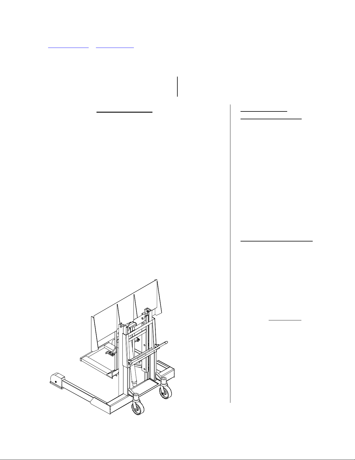
MODEL JMD-1000 MULTI-PURPOSE TOTE DUMPER
Serial number ____________
Warnings & Safety Instructions .....………………..… 2
Operation Instructions ……………………….….…… 3
Routine Maintenance & Safety Checks ……………… 4
MPORTANT NOTES
I
Ensure that all employees understand and follow the following.
o Read and understand the owner’s manual before using or servicing
the tote dumper.
o The load must be removed and the carriage fully lowered before any
work is performed on the tote dumper.
o Ensure that all safety and warning labels stay in place and are
legible.
o Do not use the tote dumper if any damage or unusual noise is
observed.
o Always watch the container carefully when the tote dumper is in
operation.
o The tote dumper is intended for use only on compacted, improved
surfaces.
o Do not use brake fluid or jack oils in the hydraulic system. If oil is
needed, use an anti-wear hydraulic oil with a viscosity grade of
150 SUS at 100°F, (ISO 32 cSt @ 40°C), or Dexron transmission fluid.
o Contact the manufacturer for any needed MSDS information.
♦ Do not perform any modifi cations to the tote dumper without the
manufacturer’s approval. Failure to receive authorization for
changes to the equipment could void the warranty.
♦ Maintenance and repairs are to be done only by personnel qualified
to perform the required work. Consideration will not be given for
warranty repair labor charges without prior written authorization by
the manufacturer.
Electrical & Hydraulic Diagrams & BOM ………..…. 5-9
Troubleshooting …………………………....….……… 10
Warranty …………………………………….….…..…. 11
MANUAL
WHEN ORDERING
REPLACEMENT PARTS:
We take pride in using quality
parts on the equipment we
manufacture. We are not
responsible for equipment
problems resulting from the use
of unapproved replacement
parts.
To order replacement or
spare parts for this equipment,
contact the factory.
In any communication with
the factory please be prepared
to provide the machine’s serial
number, which is indicated on
the machine dataplate.
RECEIVING INSTRUCTIONS
Every unit is thoroughly
tested and inspected prior to
shipment. However, it is
possible that the unit could
incur damage during transit.
Inspect the unit closely when
it arrives. If you see evidence
of damage or rough handling to
either the packaging or to the
product when it is being
unloaded, immediately
note of it on the Bill Of Lading!
It is important that you
remove the product’s packaging
upon its arrival to ensure that
there is no concealed damage
or to enable a timely claim with
the carrier for freight damage.
Also verify that the product
and its specifications are as
ordered.
make a
V
ESTIL MFG. CO./T&S EQPT. CO. 1 of 11
Page 2

WARNINGS AND SAFETY INSTRUCTIONS, MODEL JMD
Ensure that all employees understand and follow the following instructions.
¾ Read and understand the owner’s manual before using or servicing the dumper.
¾ Inspect the tote for damage before each lift. Do not attempt to pick up the tote unless it is in
good condition.
¾ Always have the floor lock engaged solidly with the floor surface when the dumper is in operation.
¾ Verify that the tote is engaged and held securely by the dumper before proceeding to raise the
tote.
¾ Always watch the dumper and the tote carefully when the dumper is in operation.
¾ Stand away from the side of the dumper when it is in operation. Stay clear of any potential pinch
and shear points.
¾ Be alert to the possibility of splashing or flying material when dumpin g loads.
¾ Do not use the dumper if any damage or unusual noise is observed.
¾ Do not perform any modifications to the dumper without the manufacturer’s approval. Failure to
receive authorization for changes to the equipment could void the warranty.
¾ Maintenance and repairs are to be done only by personnel qualified to perform the required work.
¾ The dumper must be fully lowered, power should be disconnected, and the tote should be removed
from the dumper before any maintenance or repairs are performed on the dumper.
¾ Ensure that all safety and warning labels stay in place and are legible. See the labels page in this
manual.
¾ Do not use brake fluid or jack oils in the hydraulic system. If oil is needed, use an anti-wear
hydraulic oil with a viscosity grade of 150 SUS at 100°F, (ISO 32 @ 40°C), or a
non-synthetic automatic transmission fluid.
¾ Use only replacement parts either supplied or approved by the manufacturer.
Page 3

OPERATION INSTRUCTIONS -- JMD
Loading:
The load rating is shown on the machine dataplate located at the lower right side of
the frame (relative to the push handle side) . It indicates the net capacity of both
the multi-purpose tote and the tote dumper. Injury to personnel or permanent
damage to the dumper or could result from exceeding the listed capacity.
The multi-purpose tote dumper is designed to transport and dump material from
our model MPT-1 ½ cubic yard polyethylene tote.
To load the tote onto the dumper, ensure that the carriage is in the fully lowered
position. Roll the higher side (the back side) of the tote up against the dumper’s
carriage, centered horizontally. The tote will be picked up automatically when the
carriage is raised.
Operation:
The dumper is supplied with a constant-pressure (dead-man) pushbutton control.
Pressing the “UP” pushbutton will turn on the power unit to raise the carriage. The
carriage will raise only while the control is pressed. Upon releasing the control, the
carriage will stop and hold its position. A limit switch will turn off the motor when
the carriage reaches its maximum rotation angle.
Pressing the “DOWN” pushbutton will energize the lowering valve to allow the
carriage to descend. Again, releasing the control will stop the carriage movement,
and the unit will hold its position. Be certain no part of any person or object is
under any part of the carriage before lowering the unit.
In the event that the load exceeds the dumping capacity, the hydraulic system’s
relief valve will open and not allow the unit to lift.
Safety:
Keep all personnel clear of the machine when it is in operation.
Never use the dumper if it is in need of repairs or if it seems to be malfunctioning.
Use only with approved totes that are in good condition.
Notify maintenance personnel if you notice anything out of the ordinary, such as odd
noises, erratic motion, or damage to any part of the lift or its components.
Ordering replacement parts:
We take pride in using quality parts on the equipment we manufacture. We are not
responsible for equipment problems resulting from the use of unapproved
replacement parts.
To order replacement or spare parts for this equipment, contact the factory.
In any communication with the factory please be prepared to provide the machine’s
serial number, which is indicated on the machine dataplate.
1 of 1
Page 4

Routine Maintenance & Safety Checks -- JMD
¾ Care should be taken to identify all potential hazards and comply with applicable safety procedures
before beginning work.
¾ Fully lower the carriage to the floor before beginning any inspection or work on the unit.
¾ Only qualified individuals trained to understand mechanical devices and their associated electrical
and hydraulic circuits should attempt troubleshooting and repair of this equipmen t
(A) Before each use inspect for the following:
1.) Frayed wires
2.) Oil leaks
3.) Pinched or chafed hoses
4.) Damaged or loose parts.
5.) Damage or structural deformation to the structural members, the
cylinder brackets, etc.
6.) Unusual noise or binding, or evidence thereof.
7.) Floor lock makes solid contact with the floor surface.
8.) Proper functioning of the upper travel limit switch.
(B) In addition to the above, inspect monthly for:
1.) The oil level. Oil should be 1” to 1½” below the reservoir’s fill hole
with the chute fully tilted.
2.) Worn or damaged hydraulic hoses and electrical wires.
3.) Proper operation of the tote lifting hooks.
4.) Pivot point wear at the hinge pins and cylinder ends.
5.) Intact pin and clevis retaining rings and / or fasteners.
6.) Looseness, wear, or damage to the casters’ bearings, mounting
hardware, or surface material.
7.) Excess wear to the floor lock friction pad.
8.) Unusual noises.
9.) Information and warning labels being in place and in good condition.
10.) The need to clean off dirt and debris.
(C) Yearly inspection
The oil should be changed if the oil darkens, becomes gritty, or turns a
milky color (indicating the presence of water). Replace with an anti-wear
hydraulic oil with a viscosity grade of 150 SUS at 100°F, (ISO 32 @
40°C). Ex: AW 32 or HO 150 hydraulic fluid, or Dexron transmission
fluid.
1 of 1
Page 5

MOTOR & TRANSFORME R CONNECTIO N DIAGRAMS
CAUTION!
If the motor voltage is changed, the wire on the control transformer’s
primary wire has to be changed to match the new motor voltage also.
Page 6

ELECTRICAL DIAGRAMS – MODULAR POWER UNITS
Page 7

HYDRAULIC DIAGRAM – LIFT-HOLD-LOWER CIRCUITS
¾ Care should be taken to identify all potential hazards and comply with applicable safety procedures before
beginning work.
¾ Raise the lift and install the maintenance props before beginning any inspections or work on the unit.
¾ Only qualified individuals trained to understand mechanical devices and their associated electrical and
hydraulic circuits should attempt troubleshooting and repair of this equipment
CAUTION: Do not use brake fluid or jack oils in the hydraulic system. If oil is needed, use an anti-wear hydraulic
oil with a viscosity of 150 SUS at 100°F (ISO 32 @ 40°C), or non-synthetic transmission fluid.
Page 8

DRAWING NUMBER
REV.
DWG #:
073003JY-2A
REV.
ECR #
DATE
REVISIONS
INITIAL
073003JY-2A
REV.
9
7
21
12
10
11
14
16 17 18
16 17 19 20
ITEM REQ PART NO. DESCRIPTION
10
15
13
3
22
8
2
ITEM REQ PART NO. DESCRIPTION
1 1 4JY1119 BASE
1 1 4JY1119 BASE
2 1 ELECTRIC BOX (SEE PAGE 2)
2 1 ELECTRIC BOX (SEE PAGE 2)
3 1 21-034-005 AC ADAPTER PLUG
3 1 21-034-005 AC ADAPTER PLUG
4 4 37927 TINNERMAN CLIP
4 4 37927 TINNERMAN CLIP
5 1 99-023-001 RESERVOIR
5 1 99-023-001 RESERVOIR
6 1 MOTOR BRACE
6 1 MOTOR BRACE
4 23255 SHCS UTILITY GRADE
4 23255 SHCS UTILITY GRADE
7
7
4 33687 HIGH COLLAR LOCK WASHER
4 33687 HIGH COLLAR LOCK WASHER
8 1 BV-48 BREATHER
8 1 BV-48 BREATHER
2 29185 TPHMS, Z PLATED
2 29185 TPHMS, Z PLATED
9
9
2 29201 TPHMS, Z PLATED
2 29201 TPHMS, Z PLATED
10
10
11 2 23305 SHCS UTILITY GRADE
11 2 23305 SHCS UTILITY GRADE
2 33688
2 33688
2 33008 USS FLAT WASHER Z PLATED
2 33008 USS FLAT WASHER Z PLATED
12 1 01-627-010 MANIFOLD ASSM (SEE PAGE 2)
12 1 01-627-010 MANIFOLD ASSM (SEE PAGE 2)
13 1 01-143-906 PUMP
13 1 01-143-906 PUMP
14 1 HS52 CLAMP, WORM GEAR
14 1 HS52 CLAMP, WORM GEAR
15 1 091802JY FIBERGLASS COVER
15 1 091802JY FIBERGLASS COVER
16 3 ZB2BZ009 BASE,CONTACT BLOCK
16 3 ZB2BZ009 BASE,CONTACT BLOCK
17 3 ZB2BE101 CONTACT BLOCK N.O.
17 3 ZB2BE101 CONTACT BLOCK N.O.
18 2 ZB2BA2C
18 2 ZB2BA2C
19 1 ZB2BG4C SWITCH, KEY, 2 POSITION
19 1 ZB2BG4C SWITCH, KEY, 2 POSITION
20 1 01-134-007 LEGEND, ON - OFF
20 1 01-134-007 LEGEND, ON - OFF
21 1 99-135-003 MOTOR, ELECTRIC, 1PH
21 1 99-135-003 MOTOR, ELECTRIC, 1PH
22 6 11005 HHCS, Z PLATED
22 6 11005 HHCS, Z PLATED
6 33004 USS FLAT WASHER, Z PLATED
6 33004 USS FLAT WASHER, Z PLATED
6 33618 LOCK WASHER, Z PLATED
6 33618 LOCK WASHER, Z PLATED
6 36102 HEX NUT, Z PLATED
6 36102 HEX NUT, Z PLATED
HIGH COLLAR LOCK WASHER
HIGH COLLAR LOCK WASHER
OPERATOR, BLACK, NON-ILLUM.
OPERATOR, BLACK, NON-ILLUM.
22
22
1
6
22
4
THIS PRINT IS CONFIDENTIAL AND IS
THE PROPERTY OF
THIS PRINT SHALL NOT BE USED, COPIED OR REPRODUCED
T & S EQUIPMENT CO.
IN WHOLE OR IN PART NOR SHALL THE CONTENTS
BE REVEALED ANY MANNER TO ANYONE UNLESS WRITTEN
PERMISSION IS OBTAINED FROM
T & S EQUIPMENT CO.
REMOVE ALL BURRS AND SHARP EDGES
CONCENTRICCONCENTR
ANGLES
DECIMALS
FRACTIONSFRACTIONS
x.xxx +/- .005
x.xx +/- .010
x.x +/- .025
.006 TIR
+/- 0° 30'
+/- 1/32 +/- 1/16
.060 TIR
+/- 1° 0'
+/- .015
TOLERANCE MACHINE WELDMENT
5
4
T & S EQUIPMENT COMPANY
SCALE:
NTS
DATE:
07/30/03
MATERIAL:
APPROVED BY: DRAWN BY:
AC MODULAR POWER UNIT
DRAWING NUMBER:
073003JY-2A
J.YOUNG
SIZE: A
REV:
Page 9

DRAWING NUMBER
REV.
DWG #:
073003JY-2B
REV.
ECR #
DATE
REVISIONS
INITIAL
073003JY-2B
REV.
17
14
12
13
10
18
19
16
20
15
ITEM REQ PART NO. DESCRIPTION
ITEM REQ PART NO. DESCRIPTION
1 4 71616 TSHMS, SS
1 4 71616 TSHMS, SS
2 1 01-129-001 TRANSFORMER
2 1 01-129-001 TRANSFORMER
3 1 132560 CONTACTOR, MOTOR
3 1 132560 CONTACTOR, MOTOR
4 4 27531 PHSMS, Z PLATED
4 4 27531 PHSMS, Z PLATED
5 4 32028 HWH TEK DRILL & TAP
5 4 32028 HWH TEK DRILL & TAP
6 3" TB-TRACK RAIL, DIN
6 3" TB-TRACK RAIL, DIN
7 1 01-029-006 JUCTION BOX
7 1 01-029-006 JUCTION BOX
8 1 AB66JP PANEL, JUNCTION BOX
8 1 AB66JP PANEL, JUNCTION BOX
9 4 C500 CONNECTOR, ROMEX, 2 SCREW
9 4 C500 CONNECTOR, ROMEX, 2 SCREW
10 1 01-127-010 MANIFOLD
10 1 01-127-010 MANIFOLD
11 1 6801-06-06-NOW MJ-MAORB 90 DEG.
11 1 6801-06-06-NOW MJ-MAORB 90 DEG.
12 1 99-153-011 VALVE, CHECK
12 1 99-153-011 VALVE, CHECK
568-015-BN70 O-RING
13 1
13 1
14 1 568-011-BN70
14 1 568-011-BN70
15 1 99-153-015 VALVE,CARTRIDGE,NC
15 1 99-153-015 VALVE,CARTRIDGE,NC
16 1 99-034-008 COIL, 24V AC
16 1 99-034-008 COIL, 24V AC
17 1 99-153-006 VALVE, PRESSURE RELIEF
17 1 99-153-006 VALVE, PRESSURE RELIEF
18 1 568-334-BN70
18 1 568-334-BN70
19 1 99-531-005 FILTER
19 1 99-531-005 FILTER
20
20
568-015-BN70 O-RING
O-RING
O-RING
O-RING
O-RING
1
1
99-153-038 FLOW CONTROL, 1.0 GPM
99-153-038 FLOW CONTROL, 1.0 GPM
9
4
5
2
7
1
5
3
REMOVE ALL BURRS AND SHARP EDGES
CONCENTRICCONCENTR
THIS PRINT IS CONFIDENTIAL AND IS
THE PROPERTY OF
THIS PRINT SHALL NOT BE USED, COPIED OR REPRODUCED
T & S EQUIPMENT CO.
IN WHOLE OR IN PART NOR SHALL THE CONTENTS
BE REVEALED ANY MANNER TO ANYONE UNLESS WRITTEN
PERMISSION IS OBTAINED FROM
T & S EQUIPMENT CO.
ANGLES
DECIMALS
FRACTIONSFRACTIONS
TOLERANCE MACHINE WELDMENT
.006 TIR
+/- 0° 30'
x.xxx +/- .005
x.xx +/- .010
x.x +/- .025
+/- 1/32 +/- 1/16
.060 TIR
+/- 1° 0'
+/- .015
9
7
8
6
9
T & S EQUIPMENT COMPANY
SCALE:
NTS
07/03/03
DATE:
MATERIAL:
APPROVED BY: DRAWN BY:
AC MODULAR POWER UNIT
073003JY-2B
J.YOUNG
SIZE: A
DRAWING NUMBER:
REV:
Page 10

SINGLE-ACTING CIRCUIT (STD. LIFT-HOLD-LOWER) TROUBLESHOOTING
Only qualified individuals trained to understand mechanical devices and their associated electrical
and hydraulic circuits should attempt troubleshooting and repair of this equipmen t
! Care should be taken to identify all potential haza rd s and comply with applicable safety procedures before beginning work.
Consult the factory for problems at time of installation, or for any proble ms not a d dress ed bel ow
(Problem, observation, remedy)
Unit doesn’t raise, motor doesn’t run.
No power supply voltage. Tripped branch circuit breaker or fuse(s).
Use a meter and conventional electrical troubleshooting techniques to determine cause of the fault.
No control voltage. Blown control relay fuse due to short in controls.
Use a meter and conventional electrical troubleshooting techniques to determine the cause of th e fault.
Unit doesn’t raise, but motor runs.
Suction screen blocked; air being drawn into the suction hose; reservoir not vented.
Solenoid valve stuck open by contam i nat i on or be nt valve st em.
Check valve stuck open by contamination.
Unit doesn’t raise (or raises slowly); noticeable noise (hum, buzz, chatter, or squeal); motor or pump becomes warm quickly.
Solenoid valve stuck open.
Low control voltage causing relay coil chatter.
Pressure relief opening.
Unit raises, but motion is jerky.
Bleed air from the cylinder per manual’s instructions in the hydraulic section.
Unit raises, but lowers very slowly when the motor stops.
Solenoid stuck open slightly by speck of contamination or a bent valve stem.
Check valve stuck open by speck of contamination.
Unit raises, but lowers quickly when the motor stops.
Solenoid valve stuck open by contam i nat i on or be nt valve st em.
Check valve stuck open by contamination.
Unit doesn’t lower.
A “snap” or “click” can be heard upon pressing the “DN” button due to a velocity fuse locking.
Bleed air from the cylinder per the owner’s manual’s instructions.
Check the load against the unit’s capacity rating.
Perimeter pinch point guard has lost continuity.
Check for a made switch, bad connection in the wiring, or a broken wire.
Solenoid coil circuit has lost continuity, or coil is bad.
Check the coil using a meter’s diode-check feature. (Checking with the meter’s ohms function will not give an
accurate indication.)
Unit lowers, but motion is jerky.
Air in hydraulic system, esp. the cylinder.
Bleed air from the cylinder per the owner’s manual’s instructions in the hydraulic section.
Unit lowers, but slower than usual.
Flow spool stuck.
Check the flow spool per the owner’s manual’s instructions in the hydraulic section.
Return line (3/8” clear hose) pinched off.
Unit lowers, but faster than usual.
Flow spool stuck.
Check the flow spool per the owner’s manual’s instructions in the hydraulic section.
Overload protection trips repeat edl y .
Motor is single-phasing, if power supply is three-phase.
Check supply voltage at disconnect, motor contactor, and motor to find where one leg of voltage is being lost.
Low supply voltage (typically only with 115V units).
Check the supply voltage when the motor is operating under load conditions.
Page 11

02/25/05 34-126-120.doc
ONE-YEAR PRODUCT WARRANTY
ONE YEAR LIMITED WARRANTY
For the original purchaser, the manufacturer warrants against defects in materials and workmanship that develop
during normal service and proper use for a period of one year after the date of shipment (not to exceed 15 months
after date of manufacture).
Any part that is determined by the manufacturer to be defective in material or workmanship will be, as the exclusive
remedy, repaired or replaced at the manufacturer’s option.
Any items returned to the factory must be pre-authorized with a return authorization number and have shipping costs
prepaid. (All non-warranty returns are subject to a minimum 20% restocking fee.)
Labor costs for warranty repairs and/or modifications are not covered unless done at the manufacturer’s facilities or
pre-approved by the manufacturer. Any modifications or repairs performed without prior written approval of the
manufacturer can void the warranty.
Warranty claims must be made in writing within said year.
This limited warranty gives the purchaser specific legal rights which vary from state to state.
LIMITATION OF LIABILITY
To the extent allowable under applicable law, the manufacturer’s liability for consequential and incidental damages is
expressly disclaimed. The manufacturer’s liability in any event is limited to, and shall not exceed, the purchase price
paid. Misuse will, and modification might, void the product’s warranty.
This warranty does not apply to claims made due to unauthorized repairs or alterations, freight damage, negligence,
accidents, abuse, misuse, or misapplication of the equipment.
This warranty does not cover costs of labor or consequential damages including, but not limited to: business
interruption costs; lost profits, or; lost business opportunities.
Warranty shall not be honored for equipment having past-due invoices.
WARRANTY DISCLAIMER
The manufacturer has made a diligent effort to accurately illustrate and describe their products. However, such
illustrations and descriptions are for the sole purpose of identification, and do not express, imply, or warrant that a
given product is merchantable or fit for a particular purpose, or that the product will necessarily conform to the
illustrations or descriptions. All product specifications are subject to change without notice.
DISPOSITION
The manufacturer will make a good faith effort to effect prompt correction or other adjust ment with respect to any
product that proves to be defective within the Limited Warranty Period.
The provisions of the warranty shall be construed and enforced in accordance with the Uniform Commercial Code and
laws as enacted in the State of Indiana.
VESTIL MFG. CO./T&S EQPT. CO. 1 of 1
 Loading...