

Page 1
01/08 HPC-400, 22-126-120, 0108
VESTIL MANUFACTURING CORP.
2999 N. Wayne St., Angola, IN 46703
Ph: 260-665-7586 · Fax: 260- 6 65-1339
E-mail: sales@vestil.com · Website: www.vestil.com
OWNER’S
MANUAL
MODEL HPC-400 HYDRAULIC PAIL CRUSHER
Serial number ____________
Assembly / Installation Instructions ………………..… 2
Operation Instructions ……………………….……… 3-4
Routine Maintenance & Safety Checks ……………… 5
Inspection & Testing Procedures (hoists) ...…….… …. 6
Exploded Structural Parts Drawing & BOM ………... 7-8
IMPORTANT NOTES, WARNINGS AND SAFETY INSTRUCTIONS
Ensure that all employees understand and follow the following.
* Failure to read and understand this owner’s manual before using or
servicing the pail crusher constitutes a misuse of the product. All
persons who will install, use, or care for this product must be familiar
with this material.
o The crushing platen must be secured against dropping before any work is
performed on the hydraulic system.
o Ensure that all information / safety / warning labels stay in place and
remain legible.
o Do not use the pail crusher if any damage or unusual noise is observed.
o Always verify that the cabinet door is securely closed before the crusher
is put into operation.
o The pail crusher is intended for crushing steel pails (standard 5-gallon and
smaller) in non-classified indoor environments.
o Do not use brake fluid or jack oils in the hydraulic system. If oil is
needed, use an anti-wear hydraulic oil with a viscosity grade of
150 SUS at 100°F, (ISO 32 cSt @ 40°C), or Dexron transmission fluid.
o Contact the manufacturer for any needed MSDS information.
♦ Do not perform any modifications to the pail crusher without the
manufacturer’s approval. Failure to receive authorization for changes to
the equipment could void the warranty.
♦ Maintenance and repairs are to be done only by personnel qualified to
perform the required work. Consideration will not be given for warranty
repair charges without prior written authorization by the manufacturer.
Electrical & Hydraulic Diagrams & BOM …………. 9-12
Power Unit’s Operation ………………...…..………... 13
Troubleshooting …………………………....………… 14
Safety Label Identification .............................................15
Warranty …………………………………….……..…. 16
WHEN ORDERING
REPLACEMENT PARTS:
We take pride in using quality
parts on the equipment we
manufacture. We are not
responsible for equipment
problems resulting from the use
of unapproved replacement
parts.
To order replacement or
spare parts for this equipment,
contact the factory.
In any communication with
the factory please be prepared
to provide the machine’s serial
number, which is indicated on
the machine dataplate.
RECEIVING INSTRUCTIONS
It is possible that this product
could incur damage during
transit.
Inspect the unit closely when
it arrives. If you see evidence
of damage or rough handling to
either the packaging or to the
product when it is being
unloaded, immediately
note of it on the Bill Of Lading!
It is important that you
remove the product’s packaging
upon its arrival to ensure that
there is no concealed damage
or to enable a timely claim with
the carrier for freight damage.
Also verify that the product
and its specifications are as
ordered.
make a
ESTIL MFG. CO. 1
V
Page 2

01/08 HPC-400, 22-126-120, 0108
INSTALLATION INSTRUCTIONS – HPC-400
Review this entire page before installing the pail crusher.
Consult the factory in the event there are any questions or problems at the time of installation, or for
information regarding optional features not covered by the owner’s manual.
The pail crusher must be removed from the shipping wood and securely anchored to a concrete surface before
use!
• Modifications or additions to the pail crusher without prior manufacturer’s authorization may void the crusher’s
warranty.
• The installation of this machine must be made so that it complies with all the regulations applicable to the
machine and its location. The end-user must verify that the supplied equipment is installed so it will be suited to
the environment in which it will be used.
• Installation must be performed by suitably trained personnel with access to the appropriate equipment. The
electrical aspects of the installation should be performed by an electrician.
---------------------------------------------------------------------------------------
For a typical installation of a standard pail crusher, you will need the following:
1. A fork truck or hoisting means to unload the pail crusher from the freight truck and set it into place.
2. A smooth, level, and adequately strong concrete surface on which to mount the pail crusher.
3. Concrete anchors, a masonry drill, a masonry bit, and hand tools. Consult the building’s architect or facility
engineer to determine the best size and type of hardware with which to anchor the machine to the floor.
4. An appropriate power supply circuit and electrical disconnect matching the motor voltage and current
requirements. Refer to the machine’s dataplate, to the labels on the control enclosure, and to the electrical
section in this manual for more information. The end-user is responsible for supplying the branch circuit’s required
ground fault and short-circuit protection. (Standard units have a 115V motor with overload protection provided by
a built-in thermostat, and have an 8’ long power cord with a molded 3-prong plug.)
---------------------------------------
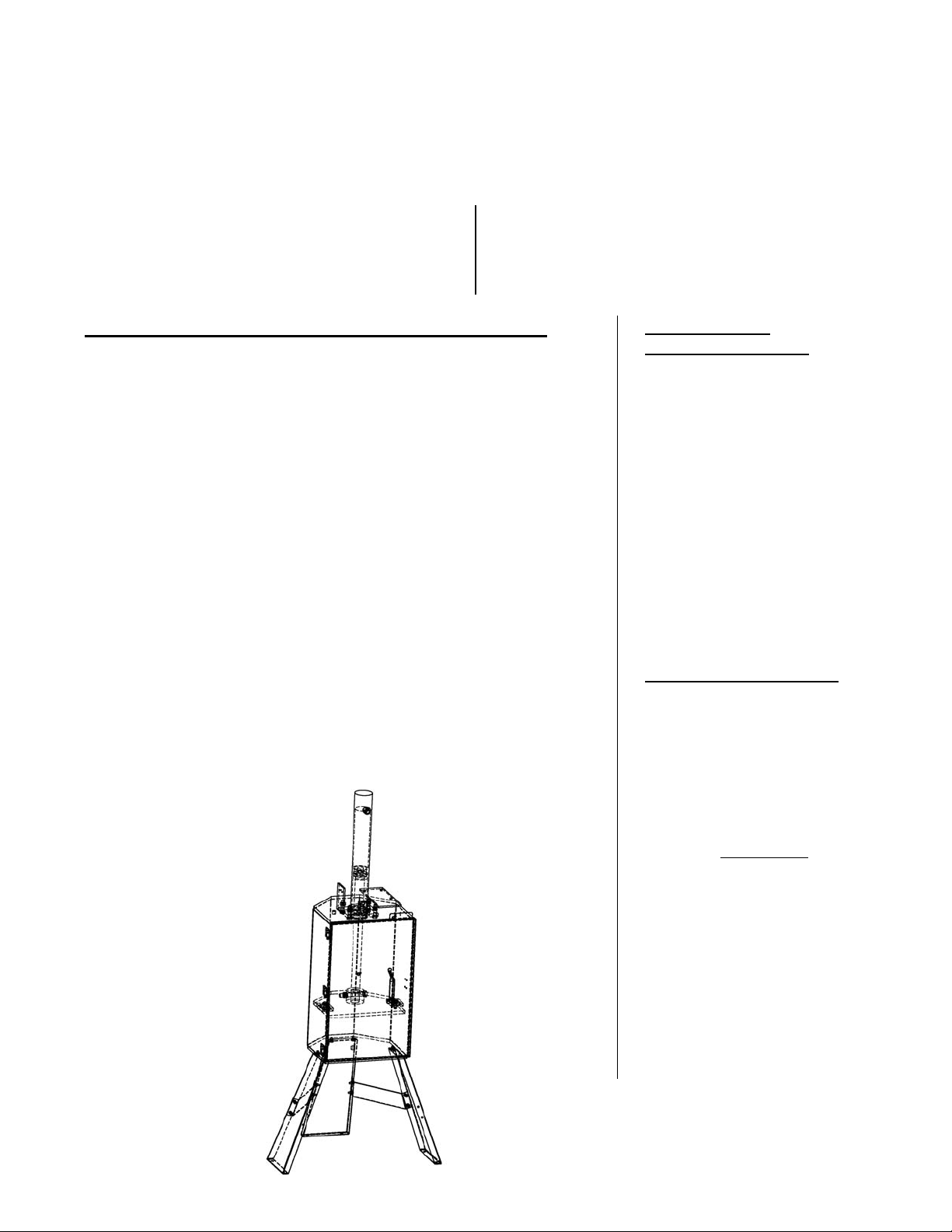
To install a standard pail crusher:
1. Move the pail crusher to the location at which it is intended to be operated. Use care to avoid damaging the power
unit’s electrical and hydraulic components.
Caution: Once it is unbanded from the skid, the pail crusher will be top-heavy and can fall over.
Note: The pail crusher’s legs can be removed to allow the pail crusher to be used on top of a heavy work table,
countertop, work bench, etc. If the legs are removed, the unit does not need to be anchored.
2. Anchor the frame to the floor (3/8” max.) through the holes located in the bottom flange of each leg.
3. If applicable, make permanent connection to the power supply, using an appropriate wiring method.
4. Operate the pail crusher through several full crush cycles. Verify that the crush platen’s upper travel limit switch
and the door limit switch function properly.
5. Check the hydraulic oil level. It should be filled to within about 1” of the reservoir’s fill hole. If oil is needed, use
an anti-wear hydraulic oil with a viscosity grade of 150 SUS at 100°F (ISO 32 at 40°C) or a non-synthetic automatic
transmission fluid.
6. Clean up any debris or spilled oil, and verify that all of the information/safety/warning labels are in good
condition.
ESTIL MFG. CO. 2
V
Page 3

01/08 HPC-400, 22-126-120, 0108
OPERATION INSTRUCTIONS – HPC-400
o Ensure that all employees involved in the operation of this crusher understand and follow these instructions!
The standard model pail crusher is suitable for use indoors in most non-classified industrial and commercial
locations. It is intended to be used to crush empty metal and fiber pails measuring up to 17½” high and 12½” in
diameter.
[Notes re: applications involving static, temperature (esp. extremes), washdown, classified areas, etc.?]
Loading:
Warning: Do not attempt to crush sealed pails or pails that are not completely empty.
Note: The original contents of the pail must be taken into account to ensure that a hazardous or unhealthy condition
will not be created (from airborne dust and vapors, etc.) when it is crushed.
Place an empty, unsealed pail on the floor of the cabinet. Center the pail so that there is a gap all the way around
the pail to allow for the pail’s diameter to increase as it crushes.
Operation:
Warning: The cabinet door must be closed and securely latched before cycling. Injury to personnel or permanent
damage to the pail crusher could result from operating it with the cabinet door unsecured.
Caution: Keep personnel away from the front of the machine when it is in operation.
Press and release the “CYCLE START” pushbutton. The motor will turn on and the crushing platen will lower to crush
the pail. When the pail is flattened, the platen will automatically raise back to the top of the cabinet and the crusher
will turn off.
Open the door and remove the crushed pail.
Warning: Do not attempt to open the cabinet door when the crusher is in operation.
Caution: Never use the pail crusher if any damage or unusual noise is observed, if it is in need of repairs, or if it seems
to be malfunctioning. Notify your supervisor or maintenance personnel if you notice anything out of the ordinary.
Ensure that all information/safety/warning labels stay in place and are legible. Refer to the labels page in this
manual.
ESTIL MFG. CO. 3
V
Page 4

01/08 HPC-400, 22-126-120, 0108
ROUTINE MAINTENANCE & SAFETY CHECKS – HPC-400
o Warning: Care should be taken to identify all potential hazards and comply with applicable safety procedures
before beginning work.
o Warning: Fully lower the crushing platen and remove all hydraulic pressure before beginning any work on the
hydraulic system.
o Only qualified individuals trained to understand mechanical devices and their associated electrical and hydraulic
circuits should attempt troubleshooting and repair of this equipment
(A) Inspect daily for:
1.) Frayed or damaged wires.
2.) Oil leaks.
3.) Pinched or chafed hoses.
4.) Damage or structural deformation to the cabinet, legs, or door latching mechanism.
5.) Unusual noise or binding, or evidence thereof.
6.) Proper functioning of the upper travel and door switches.
(B) Inspect monthly for:
1.) The hydraulic fluid level. It should be maintained about 1”-1½” below the reservoir’s fill hole with the
crushing platen in the fully raised position. See below for the hydraulic oil specification.
2.) Worn or damaged hydraulic hoses and electrical wires.
3.) Bending of the crushing platen’s hydraulic cylinder rod.
4.) The integrity of the legs’ anchor bolts, and for cracks in the concrete around them.
5.) Condition and tightness of the pushbuttons.
6.) Unusual noises or movement during operation.
7.) All the information/safety/warning labels being in place and in good conditio n .
8.) The need to clean off dirt and debris.
The oil should be changed if the oil darkens, becomes gritty, or turns a milky color (indicating the presence of
water). Replace with an anti-wear hydraulic oil with a viscosity grade of 150 SUS at 100°F, (ISO 32 at 40°C). Ex:
AW 32 or HO 150 hydraulic oil, or a non-synthetic transmission fluid such as Dexron III. You may use a synthetic
transmission fluid if you flush the system with the synthetic fluid before filling the reservoir.
ESTIL MFG. CO. 4
V
Page 5
01/08 HPC-400, 22-126-120, 0108
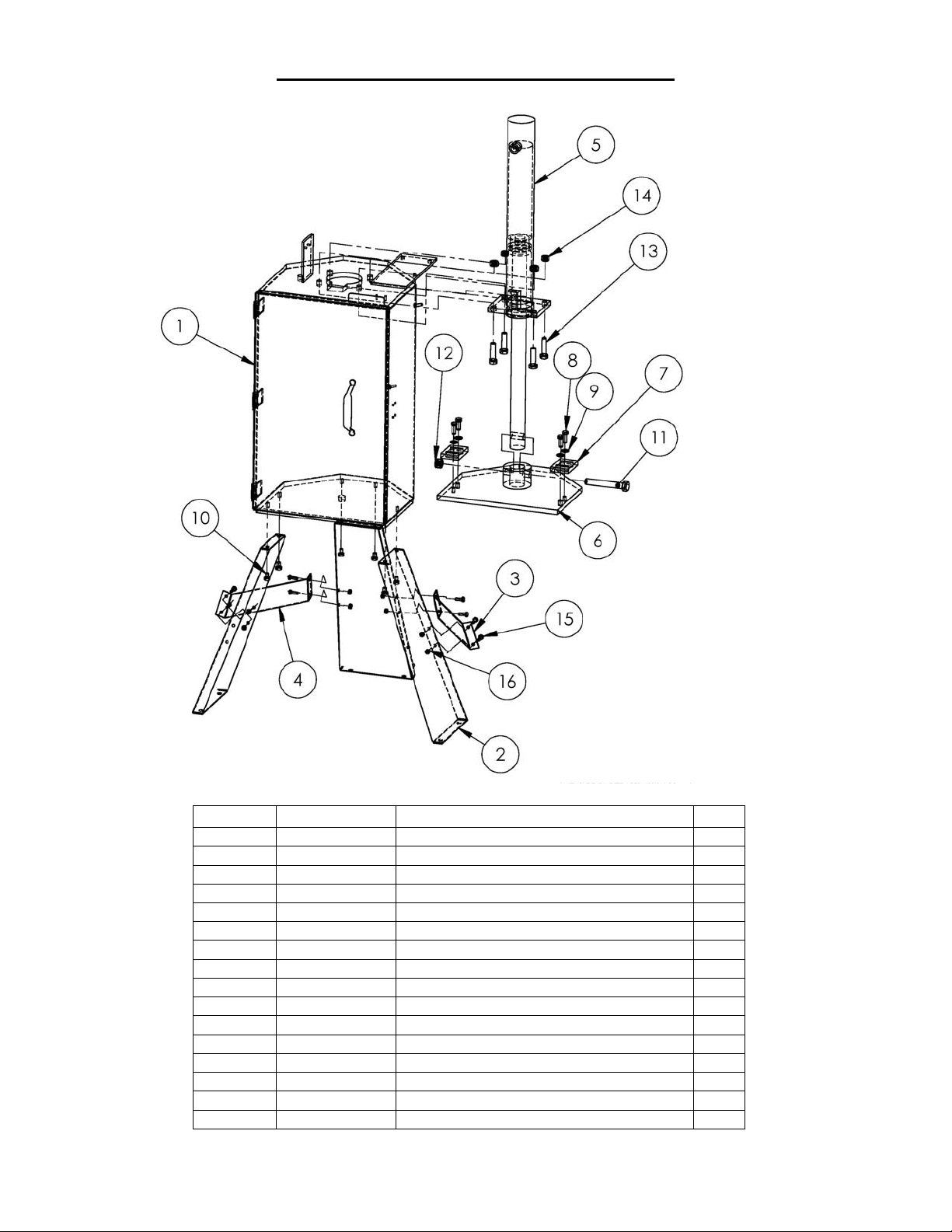
EXPLODED PARTS VIEW & BOM -- HPC-400
Item no. Part number Description Qty.
1 22-514-013 Sub-assembly, frame and door 1
2 22-014-037 Leg, frame, formed 3
3 22-514-015 Weldment, leg brace, frame, right 1
4 22-514-016 Weldment, leg brace, frame, left 1
5 22-021-006 Cylinder, 2½” x 18” (1½” rod) 1
6 22-514-014 Weldment, frame, push plate 1
7 22-01-022 Bracket, guide, push plate 2
8 A/L Screw, hex head, 3/8”16 UNC x 1” long 4
9 A/L Washer, flat, 3/8” ID 4
10 A/L Bolt, hex head, 3/8”-16 UNC x 1½” long 6
11 A/L Bolt, hex head, 5/8”-11 UNC x 4¼” long 1
12 A/L Nut, hex, 5/8”-11 UNC 1
13 A/L Bolt, hex head, 1/2”-13 UNC x 1¼” long 4
14 A/L Nut, hex, 1/2”-13 UNC 4
15 A/L Bolt, hex head, 1/4”-20 UNC x ¾” long 8
16 A/L Nut, hex, 1/4”-20 UNC 8
ESTIL MFG. CO. 5
V
Page 6

01/08 HPC-400, 22-126-120, 0108
MOTOR & TRANSFORMER CONNECTION DIAGRAMS
CAUTION! If the motor voltage is changed, the wire on the control transformer’s primary wire has to be changed to
match the new motor voltage also.
ESTIL MFG. CO. 6
V
Page 7

01/08 HPC-400, 22-126-120, 0108
ELECTRICAL LADDER DIAGRAM -- HPC-400
o Warning: Care should be taken to identify all potential hazards and comply with applicable safety procedures before
beginning work. Verify that all system pressure and power have been removed before attempting to work on the
electrical or hydraulic systems.
o Warning: The platen must be fully lowered and the hydraulic pressure removed before working on the hydraulic
system.
o Only qualified individuals trained to understand mechanical devices and their associated electrical and hydraulic
circuits should attempt troubleshooting and repair of this equipment.
ESTIL MFG. CO. 7
V
Page 8

01/08 HPC-400, 22-126-120, 0108
ELECTRICAL INTERCONNECTION DIAGRAM -- HPC-400
o Warning: Care should be taken to identify all potential hazards and comply with applicable safety procedures before
beginning work. Verify that all system pressure and power have been removed before attempting to work on the
electrical or hydraulic systems.
o Warning: The platen must be fully lowered and the hydraulic pressure removed before working on the hydraulic
system.
o Only qualified individuals trained to understand mechanical devices and their associated electrical and hydraulic
circuits should attempt troubleshooting and repair of this equipment.
ESTIL MFG. CO. 8
V
Page 9

01/08 HPC-400, 22-126-120, 0108
HYDRAULIC DIAGRAM – LIFT-HOLD-LOWER CIRCUITS
o Warning: Care should be taken to identify all potential hazards and comply with applicable safety procedures
before beginning work. Fully lower or secure the crushing platen, and verify t hat all system pressure and power
have been removed, before attempting to work on the hydraulic system.
o Only qualified individuals trained to understand mechanical devices and their associated electrical and hydraulic
circuits should attempt troubleshooting and repair of this equipment
o Caution: Do not use brake fluid or jack oils in the hydraulic system. If oil is needed, use an anti-wear hydraulic
oil with a viscosity of 150 SUS at 100°F (ISO 32 @ 40°C), or non-synthetic transmission fluid.
ESTIL MFG. CO. 9
V
Page 10

01/08 HPC-400, 22-126-120, 0108
BILL OF MATERIALS -- HPC-400
E
LECTRIC / HYDRAULIC BOM -- HPC-400
Item #: Description Part number Qty.
1 Reservoir 06-023-001 1
2 Plug, breather BV-38 1
3 Clamp HS64 1
4 O-ring 568-340 1
5 Valve, check 99-153-011 1
6 Valve, 4-way, 2-position directional 99-153-008 1
Solenoid, 24VAC 99-034-008 1
7 Plug, cavity CPO8-20-N 1
8 Fitting, hydraulic, 90° 6801-06-06N-WO 2
9 Valve, pressure relief 99-153-004 1
10 SHCS, 5/16” - 18 UNC x 1” long 23255 4
Washer, lock, high collar, 5/16” ID 33687 4
11 SHCS, 3/8” - 16 UNC x 1” long 23305 2
Washer, lock, high collar, 3/8” ID 33688 2
Washer, flat, 3/8” ID 33008 2
12 Filter, hydraulic, 3/4” x 3 5/8” long, 20 mesh 01-031-005 1
13 Pump, hydraulic, .06 in³/rev 01-143-905 1
14 Motor, electric, 3/4HP, 115V 99-135-003 1
15 Manifold, hydraulic 17-127-001 1
16 O-ring 568-015-BN70 1
17 O-ring 568-011-BN70 1
18 Plug, cavity (ports 2 to 3 open) CP08-30-N-X 1
19 Switch, pressure, adjustable, 3000 psi 99-022-004 1
ESTIL MFG. CO. 10
V
Page 11

01/08 HPC-400, 22-126-120, 0108
THE POWER UNIT’S OPERATION – HPC-400
The electric / hydraulic pail crusher utilizes an electric motor directly coupled to a gear-type hydraulic pump to
produce the needed fluid pressure and flow to allow the cylinder to perform the work of crushing pail.
A hydraulic manifold houses the hydraulic control components, and is bolted directly onto the gear pump.
The power unit’s hydraulic components are all rated for 3,000 psi working pressure.
¬ Important parts of the power unit include:
• The electric motor. Available for all nominal voltages and phases of power supply.
• The gear pump. Its shaft is coupled directly to the shaft of the electric motor.
• The check valve. Its purpose is to prevent the backflow of fluid through the pump. When stopped before a cycle is
completed, the crushing platen will hold its position.
• The pressure relief valve. Its job is to open a path for fluid to flow back to the reservoir in the event that the fluid
pressure built up by the pump exceeds 3,000 psi.
• The solenoid-operated directional valve. This is an electrically-operated cartridge valve. It contains a screen to
keep contaminants from entering the valve.
• The pressure-compensated flow control spool. This rests under the lowering valve, and regulates the fluid flow
back to the reservoir when the valve opens. It allows the forks to always lower at the same rate regardless of
whether there is a load on the fork carriage or not.
• The hydraulic cylinder. This is a double-acting cylinder.
• The hydraulic fluid. The system uses HO150 hydraulic fluid. Any anti-wear hydraulic fluid with a viscosity grade of
150 SUS at 100°F (ISO 32 @ 40°C) such as AW-32 or Dexron transmission fluid are acceptable.
When a pail is loaded and the cabinet door is closed, press the CYCLE START pushbutton. The motor turns, and in
turning it spins the hydraulic gear pump. Hydraulic fluid is pumped through the check valve, through the energized
directional valve, and to the cylinder, which extends to lower the crushing plate.
When the cylinder either strokes out or the pail is crushed completely, a pressure switch causes the directional
valve solenoid to de-energize, the pilot-operated check valve in the hydraulic manifold opens, and the cylinder
retracts to raise the crushing platen.
ESTIL MFG. CO. 11
V
Page 12

01/08 HPC-400, 22-126-120, 0108
TROUBLESHOOTING GUIDE -- HPC-400
Warning: Always secure the platen by blocking it up or lower it fully, and disconnect the power supply,
before opening the hydraulic system.
Consult the factory for problems at time of installation, or for any problems not addressed below.
Problem: Possible cause(s): Action:
Motor doesn’t run when “CYCLE
START” button is pressed.
Motor runs, but platen does not
lower.
Motor hums noticeably or is
otherwise noisy, but the platen
does not move downward, or
moves downward only slowly.
Crushing platen cycles up and down
a few inches rapidly when the
“CYCLE START” button is pressed
and held.
Crushing platen lowers, but only
while the “CYCLE START” button
is pressed.
Platen lowers, but won’t return to
the top.
Pails are not crushing completely.
Platen returns to the top.
Crushing platen drifts downward
when the crusher is not being
used.
Stop button is engaged.
Door switch is not engaged.
No output from the transformer’s
secondary winding, or the in-line
fuse is blown.
No supply voltage.
Bad connection in the control
circuit.
Open motor relay coil or motor
thermostat.
If three-phase, wrong motor
rotation.
No pump output.
Fluid level is low.
Supply voltage is too low.
Motor is “single-phasing” (three-
phase motors only).
Motor’s start capacitor or
centrifugal switch is open
(single-phase motors only).
Low fluid level in the reservoir.
“Cylinder Raised” limit switch is
staying engaged when the platen
is fully raised.
Operator is not holding the button
long enough.
The motor relay’s auxiliary contact
is dirty or is open.
The pressure switch setting is
higher than the system pressure.
The pressure switch setting is too
low.
System check valve is leaking. Run the crushing platen down fully,
Verify that the button operator is
pulled completely outward. If so,
test its contact block with an
meter.
Verify that the door switch plunger
is pushed in far enough to close the
switch.
Test the fuse, and for 24VAC at the
secondary winding; replace
components if bad.
Test for line voltage at the motor
relay’s line terminals.
Test all components and wiring with
a meter.
Test with a meter; replace if bad.
(Motor thermostat can be
bypassed.)
Verify motor rotates CCW when
viewed from the shaft end.
Check for fluid flow by loosening the
hose fitting at the top end of the
cylinder to check for fluid flow.
The fluid level should be within 1½”
of the top of the reservoir when
the platen is fully raised.
Verify the supply voltage at the
motor relay’s load terminals while
the motor is on. If voltage drop is
10% or more, install a properly
sized dedicated supply circuit.
Verify that all phases are present.
Determine cause of loss of voltage
on one phase, and correct.
Test both components with a meter.
Loosen the hose fitting at the top
end of the cylinder to check for
fluid flow.
Inspect for the cause of the hangup.
Verify that the limit switch’s arm
and the switch’s actuator bolt
both move freely.
Hold button down long enough for
the platen to drop a couple of
inches.
Test with a meter. If defective,
replace the relay.
Place a pressure gauge in the
hydraulic system to verify that
the pump is developing adequate
pressure (3,000 psi).
then remove, inspect, clean, and
replace the check valve (item #5).
ESTIL MFG. CO. 12
V
Page 13

01/08 HPC-400, 22-126-120, 0108
SAFETY LABEL IDENTIFICATION
* Product safety signs or labels should be periodically inspected and cleaned by the product users as necessary to
maintain good legibility for safe viewing distance -- ANSI 535.4 (10.21). Contact the manufacturer for replacement
labels.
ESTIL MFG. CO. 13
V
Page 14

01/08 HPC-400, 22-126-120, 0108
PRODUCT WARRANTY
ONE YEAR LIMITED WARRANTY
The manufacturer warrants for the original purchaser against defects in materials and wo rkmanship under normal use
for one year after date of shipment (not to exceed 15 months after date of manufacture). Any part that is determined
by the manufacturer to be defective in material or workmanship and returned to the factory, shipping costs prepaid,
will be, as the exclusive remedy, repaired or replaced at our option. Labor costs for warranty repairs and/or
modifications are not covered unless pre-approved by the manufacturer or done at the manufacturer’s facilities. Any
modifications performed without prior written approval of the manufacturer may void warranty. This limited warranty
gives purchaser specific legal rights which vary from state to state.
All specifications are subject to change without notice.
LIMITATION OF LIABILITY
To the extent allowable under applicable law, the manufacturer’s liability for consequential and incidental damages is
expressly disclaimed. The manufacturer’s liability in any event is limited to, and shall not exceed, the purchase price
paid. Misuse or modification may void warranty.
Warranty does not cover labor or consequential damages including, but not limited to, business interruption costs, lost
profits, or lost business opportunities.
WARRANTY DISCLAIMER
The manufacturer has made a diligent effort to accurately illustrate and describe their products. However, such
illustrations and descriptions are for the sole purpose of identification, and do not express or imply a warranty that the
products are merchantable or fit for a particular purpose, or that the products will necessarily conform to the
illustrations or descriptions.
The provisions of the warranty shall be construed and enforced in accordance with the Uniform Commercial Code and
laws as enacted in the State of Indiana.
DISPOSITION
Our company will make a good faith effort for prompt correction or other adjustment with respect to any product that
proves to be defective within the Limited Warranty Period. Warranty claims must be made in writing within s aid year.
ESTIL MFG. CO. 14
V
 Loading...