

Page 1
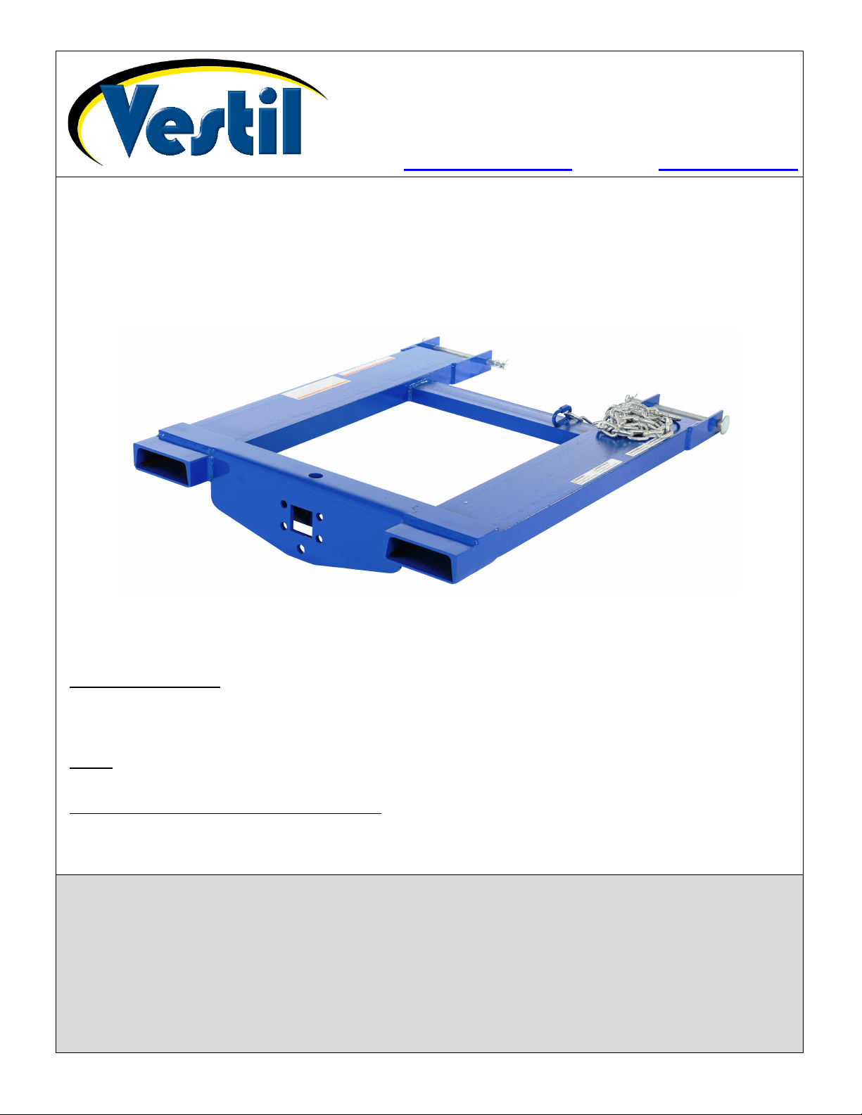
Table of Contents Rev. 10/17/2019 HOOK-BASE MANUAL
Web: www.vestilmfg.com e-mail: info@vestil.com
Vestil Manufacturing Corp.
2999 North Wayne Street, P.O. Box 507, Angola, IN 46703
Telephone: (260) 665-7586 -or- Toll Free (800) 348-0868
Fax: (260) 665-1339
HOOK-BASE
Instruction Manual
Receiving instructions:
After delivery, remove the packaging from the product. Inspect the product closely to determine
whether it sustained damage during transport. If damage is discovered, record a complete description of
it on the bill of lading. If the product is undamaged, discard the packaging.
NOTE: The end-user is solely responsible for confirming that product design, use, and maintenance
comply with laws, regulations, codes, and mandatory standards applied where the product is used.
Replacement Parts and Technical Assistance:
For answers to questions not addressed in these instructions and to order replacement parts, labels,
and accessories, call our Technical Service and Parts Department at (260) 665-7586. The department
can also be contacted online at http://www.vestilmfg.com/parts_info.htm.
Signal Words….……………………..…………………………………………………………………………………….…….. 2
Hazards of Improper Use…..……………………………………………………………..…………………………………..… 2
Specifications…………………………………………………………………………………….………………………… 3, 4, 5
Record of Normal Condition………………………………………………………………………………………………….… 5
Exploded View & Bill of materials………………………………………….……...…………….………………………….…. 6
Using the HOOK-BASE……………………………..…………………………………………………………………….. 6, 7, 8
Inspections & Maintenance……………………………………………………………………………………………………... 9
Labeling Diagram……...………………………………………………………………………………………………………… 9
Limited Warranty…...…………………………………………………………………………………………………………….10
Table of Contents
Table of Contents Copyright 2016 Vestil Manufacturing Corp Page 1 of 10
Page 2
Table of Contents Rev. 10/17/2019 HOOK-BASE MANUAL
Signal Words:
This manual classifies personal injury risks and situations that could lead to property damage with SIGNAL
WORDS. A safety message appears with a signal word that describes an improper/dangerous use of the product.
The signal word indicates the seriousness of the injury that could result from the described use.
Identifies a hazardous situation which, if not avoided, COULD result in DEATH or
Identifies practices likely to result in product/property damage, such as operation that might
SERIOUS INJURY.
damage the product.
Each person who assembles, installs, uses, or maintains this product should read the entire manual in advance
and fully understand the directions. If after reading the manual you do not understand an instruction, ask your
supervisor or employer for clarification, because failure to adhere to the directions in this manual might result in
serious personal injury.
Hazards of Improper Use:
Vestil strives to identify foreseeable hazards associated with the use of its products. However, no manual can address
every conceivable risk. The most effective way to avoid injury from misusing this product is to exercise sound judgment
whenever the HOOK-BASE is in use
Improper or careless use of this product might result I serious personal injuries.
• Read and understand the entire manual before assembling, installing, using or servicing the product. Read
the manual to refresh your understanding of proper use and maintenance procedures whenever necessary.
• DO NOT exceed the 4,000 lb. (1,818.2kg) capacity/maximum rated load. See Label 287 on product; also see Labeling
Diagram on p. 9.
• Inspect the product before each use following the instructions in Inspections & Maintenance on p. 9. DO NOT use the
HOOK-BASE unless it is in normal condition.
• Before attaching the HOOK-BASE to the coupler of a piece of towable equipment, inspect the coupler and latch.
Confirm that all parts are in good condition. DO NOT use the HOOK-BASE to tow equipment UNLESS the coupler
seats onto the correct ball hitch and latches properly. ONLY USE THE HOOK-BASE TO PUSH TOWED EQUIPMENT.
DO NOT PULL EQUIPMENT WITH THIS DEVICE!
• Whenever using the load hook, always test the soundness of the connection between the hook and the suspended
load before transporting the load. Lift the load a few inches above the ground. Load swing should be minimal and the
load should not shift. If the load is not stable while suspended, return it to the ground and adjust the load rigging.
• Minimize load swing. Position the lifting hook directly above the center of the top of the load; then attach the load to
the hook with appropriate rigging and slowly raise the load.
• DO NOT remove or obscure any label.
• Verify the placement and legibility of all labels shown in the Labeling Diagram on p. 9. DO NOT use this device
UNLESS all product labels are easily readable and undamaged.
• DO NOT ride, or sit, on the HOOK-BASE.
• DO NOT use the HOOK-BASE to tow anything while people are onboard.
• DO NOT use the lifting hook to lift any apparatus that supports people, such as a work platform.
• DO NOT leave towed equipment attached to the HOOK-BASE. Properly immobilize the equipment (e.g. with wheel
chocks) and disengage it from the towing attachment when towing is finished.
• DO NOT leave suspended loads unattended. Always disengage any load suspended from the lifting hook before
leaving it unattended.
• DO NOT modify the HOOK-BASE without written approval from Vestil. Unauthorized modifications automatically
void the Limited Warranty (p. 10) and might make the HOOK-BASE unsafe to use.
• ONLY raise the forks as high as necessary to put the trailer in a horizontal (level) position for towing.
• If using the hoist hook attachment to lift loads, only raise the forks as high as necessary to raise the load off of the
ground and to avoid contact with objects in the path of travel.
• DO NOT use the HOOK-BASE to transport anything but trailers or equipment designed to be towed. The towing
attachment, e.g. ball or pintle hook, should match the towing adapter on the trailer or other towable equipment.
• Use this HOOK-BASE consistently with the fork truck training you received.
• DO NOT use the unit UNLESS all product labels are easily readable and undamaged. See Labeling Diagram on p. 9.
.
Table of Contents Copyright 2016 Vestil Manufacturing Corp Page 2 of 10
Page 3
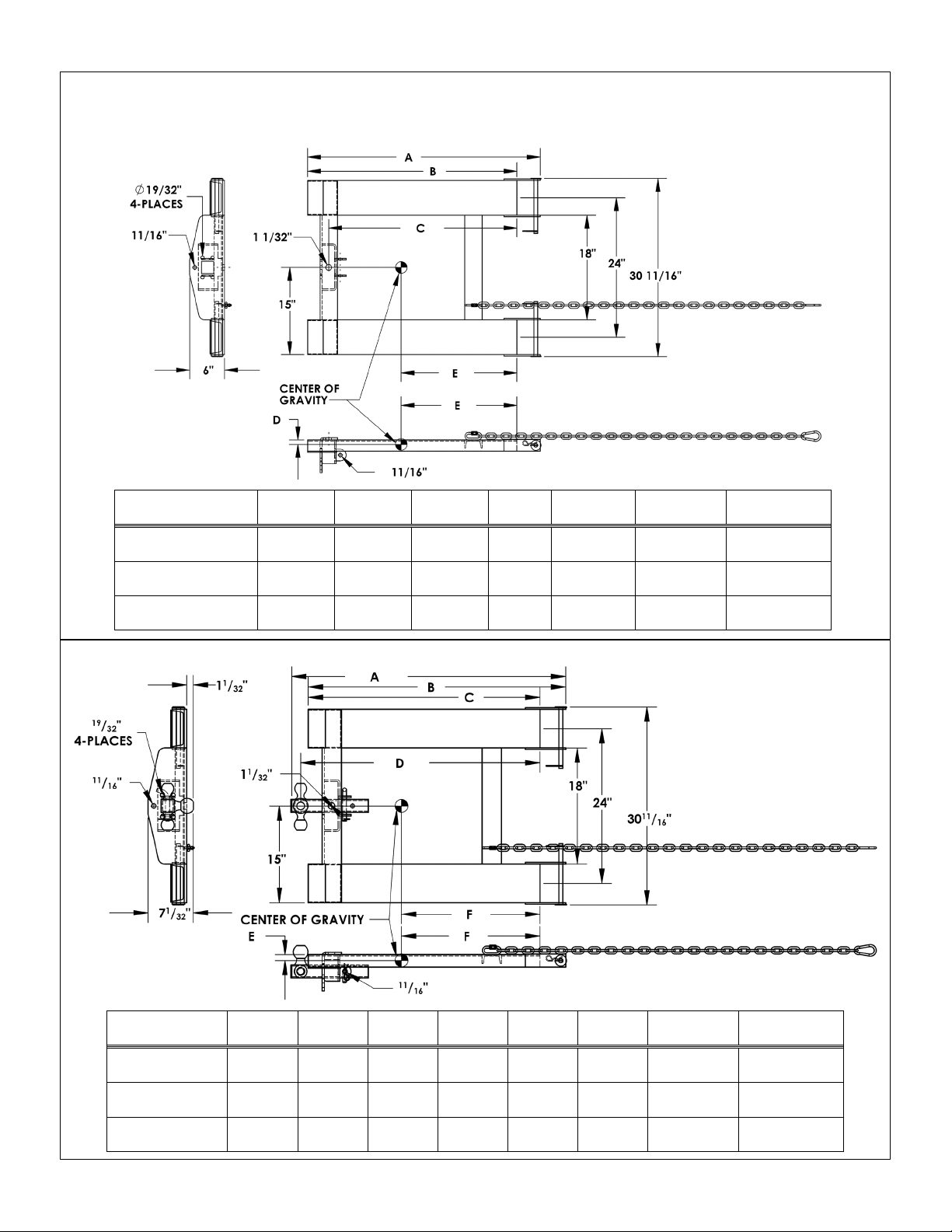
Table of Contents Rev. 10/17/2019 HOOK-BASE MANUAL
40”
101.6cm
36”
91.4cm
323/8”
82.2cm
0.77”
2.0cm
19.91”
50.6cm
4,000 lb.
1,818.2kg
88 lb.
(40kg)
46”
116.8cm
42”
106.7cm
383/8”
97.5cm
0.74”
1.9cm
23.08”
58.6cm
4,000 lb.
1,818.2kg
96 lb.
(43.6 kg)
52”
132.1cm
48”
121.9cm
443/8”
112.7cm
0.72”
1.8cm
26.23”
66.6cm
4,000 lb.
1,818.2kg
105 lb.
(47.7 kg)
4219/32”
108.2cm
40”
101.6cm
36”
91.4cm
373/16”
94.5cm
0.90”
2.3cm
21.52”
54.0cm
4,000 lb.
1,818.2kg
98 lb.
(44.5 kg)
4819/32”
123.4cm
46”
116.8cm
42”
106.7cm
433/16”
109.7cm
0.87”
2.2cm
24.85”
63.1cm
4,000 lb.
1,818.2kg
106 lb.
(48.2 kg)
5419/32”
138.7cm
52”
132.1cm
48”
121.9cm
493/16”
124.9cm
0.86”
2.2cm
28.12”
71.4cm
4,000 lb.
1,818.2kg
114 lb.
(51.8 kg)
HOOK-BASE only—
HOOK-BASE with 3-Ball
Specifications:
Dimensions and other specifications of each standard model HOOK-BASE appear in the diagrams and tables
below and on pages 4 & 5.
Model A B C D E Capacity Net Weight
HOOK-BASE-32
HOOK-BASE-38
HOOK-BASE-44
Model A B C D E F Capacity Net Weight
HOOK-BASE-32
HOOK-BASE-38
HOOK-BASE-44
No towing or lifting
attachments.
Hitch Attachment.
Installation instructions
on p. 7.
Table of Contents Copyright 2016 Vestil Manufacturing Corp Page 3 of 10
Page 4

Table of Contents Rev. 10/17/2019 HOOK-BASE MANUAL
40”
101.6cm
36”
91.4cm
1.07”
2.7cm
20.40”
51.8cm
4,000 lb.
1,818.2kg
91 lb.
(41.4kg)
46”
116.8cm
42”
106.7cm
1.02”
2.6cm
23.62”
60.0cm
4,000 lb.
1,818.2kg
99 lb.
(45 kg)
52”
132.1cm
48”
121.9cm
0.99”
2.5cm
26.81”
668.1cm
4,000 lb.
1,818.2kg
108 lb.
(49.1 kg)
4315/16”
111.6cm
40”
101.6cm
36”
91.4cm
0.90”
2.3cm
21.44”
54.5cm
4,000 lb.
1,818.2kg
97 lb.
(44.1 kg)
4915/16”
126.8cm
46”
116.8cm
42”
106.7cm
0.87”
2.2cm
24.71”
62.8cm
4,000 lb.
1,818.2kg
105 lb.
(47.7 kg)
5515/16”
142.1cm
52”
132.1cm
48”
121.9cm
0.84”
2.1cm
27.96”
71.0cm
4,000 lb.
1,818.2kg
113 lb.
(51.4 kg)
HOOK-BASE with Hook
on p. 7.
HOOK-BASE with Pintle
Specifications (continued):
Model A B C D Capacity Net Weight
HOOK-BASE-32
HOOK-BASE-38
HOOK-BASE-44
Model A B C D E Capacity Net Weight
HOOK-BASE-32
HOOK-BASE-38
and Shackle.
Installation instructions
Hook.
Installation instructions
on p. 6.
HOOK-BASE-44
Table of Contents Copyright 2016 Vestil Manufacturing Corp Page 4 of 10
Page 5

Table of Contents Rev. 10/17/2019 HOOK-BASE MANUAL
Model
Jaw Opening
Vertical Capacity
Uniform Trailer Capacity
Net Weight
40”
101.6cm
36”
91.4cm
323/8”
82.2cm
0.68”
1.7cm
21.44”
54.5cm
4,000 lb.
1,818.2kg
91 lb.
(41.4 kg)
46”
116.8cm
42”
106.7cm
383/8”
97.5cm
0.67”
1.7cm
23.58”
59.9cm
4,000 lb.
1,818.2kg
99.1 lb.
(45.0 kg)
52”
132.1cm
48”
121.9cm
443/8”
112.7cm
0.66”
1.7cm
26.77”
68.0cm
4,000 lb.
1,818.2kg
108 lb.
(49.1 kg)
HOOK-BASE with
Specifications (continued):
Model A B C D E Capacity Net Weight
HOOK-BASE-32
HOOK-BASE-38
HOOK-BASE-44
Hitch Attachments:
Ball Hitches Ball Diameter Shank Diameter Capacity Net Weight
Tow Ball. Installation
instructions on p. 6.
BALL-178 17/8” (4.8cm) 1” (2.5cm) 2,000 lb. (909.1kg) 3 lb. (1.4kg)
BALL-200 2” (5.1cm) 1” (2.5cm) 5,000 lb. (2272.7kg) 3 lb. (1.4kg)
BALL-2516 25/16” (5.9cm) 1” (2.5cm) 5,000 lb. (2272.7kg) 4 lb. (1.8kg)
HITCH-3B
Use with 3” (inner
diameter) pintle ring
Record of Normal Condition:
When the unit is first unpacked, make a written record of its condition. Include observations about all
features, i.e. pins, pin clips, welds, the frame, safety chain, quick link, and snap hook. Thoroughly
photograph the unit and all labels applied to it. Add the photographs to the record. Describe where each
label is located. This record establishes “normal condition”. During future inspections, compare your
observations to the record to determine if the unit is in normal condition. See Inspections &
Maintenance on p. 9.
PINTLE
7
/8”, 2”, & 25/
1
16”
(4.8cm; 5.1cm; 5.9cm)
1¾” (~4½ cm)
N/A (hitches permanently
mounted to 2”x2”x12”
square tube)
2,000 lb.
(909.1kg)
2,000 lb. (909.1kg)
3,500 lb. (1590.9kg)
7,500 lb. (3409.1kg)
10,000 lb.
(4545.5kg)
12 lb.
(5.5kg)
12 lb.
(4.7kg)
Table of Contents Copyright 2016 Vestil Manufacturing Corp Page 5 of 10
Page 6

Table of Contents Rev. 10/17/2019 HOOK-BASE MANUAL
TOW BALL
PINTLE HOOK
BASE: first
EQUIPMENT WITH
THIS DEVICE!
Item
Part no.
Description
Qty.
08-514-102
Frame weldment:
HOOK-BASE-42
1
#11 hitch pin clip, 1/8” x
25/8”
Tine lock
Quick
link
Front
end
Fork
Hitch
Hitch plate
Exploded View and Bill of Materials:
receiver
Using the HOOK-BASE: Refer to the Exploded View (above) for locations of features described.
OF YOUR LIFT TRUCK.BEFORE USING THIS DEVICE, US FEDERAL REGULATION 29 CFR 1910.178
REQUIRES YOU TO CONTACT THE MANUFACTURER OF YOUR LIFT TRUCK TO REQUEST:
o WRITTEN APPROVAL (29 CFR 1910.178(a)(4); AND
o MARKINGS FOR THE LIFT TRUCK THAT IDENTIFY THE ATTACHMENT AND GIVE THE APPROXIMATE
WEIGHT OF THE TRUCK AND ATTACHMENT AT MAXIMUM ELEVATION WITH A LATERALLY-CENTERED
LOAD (29 CFR 1910.178(a)(5). DO NOT USE THIS DEVICE UNTIL YOUR LIFT TRUCK IS MARKED WITH
CORRECTED CAPACITY TAGS. ONLY USE THIS DEVICE WITH LIFT TRUCKS THAY HAVE BEEN
MARKED WITH CORRECTED CAPACITY TAGS.
Step 1: Select the appropriate towing attachment and install it.
A) Insert the bolts through the four bolt holes in the
hitch plate (shown by dashed arrows).
B) Fasten the pintle hook to the HOOKapply a lock washer to each bolt; then apply a hex nut.
Fully tighten the nuts to secure the connections.
ONLY USE THE HOOK-BASE TO PUSH TOWED
EQUIPMENT. DO NOT PULL
bracket
08-514-140
1
08-514-139
HOOK-BASE-32
HOOK-BASE-38
1
1
2 45286
2
3 14-612-001 Pin, lock, weldment 2
4 09-145-018 5/16” chain 56” long 1
tube
5 08-145-041 Snap hook, 5/16” 1
USING THIS (LIFT TRUCK) FRONT END ATTACHMENT AFFECTS THE CENTER OF GRAVITY
A) Insert the tow ball
through the opening in the
top of the hitch plate.
B) Fasten the tow ball to
the HOOK-BASE: first
apply a lock washer to each
bolt; then apply a hex nut.
Fully tighten the nuts to
secure the connections.
ONLY USE THE HOOKBASE TO PUSH TOWED
EQUIPMENT. DO NOT
PULL EQUIPMENT WITH
THIS DEVICE!
Table of Contents Copyright 2016 Vestil Manufacturing Corp Page 6 of 10
Page 7

Table of Contents Rev. 10/17/2019 HOOK-BASE MANUAL
Hitch pin
clip
Locking
pin
Tine lock bracket
Secure locking pins with hitch pins
3-BALL HITCH (model HITCH-3B)
ONLY PUSH TOWED EQUIPMENT with the HOOK-BASE. DO NOT PULL EQUIPMENT WITH THIS DEVICE!
2”
25/16”
17/8”
Heel of
Side view of fork
HOOK AND SHACKLE (models HOOK-S-4 and HOOK-R-4)
Shackle
Shackle
Insert shackle pin here
NOTE:
Select the appropriate tow ball and insert the hitch through the (square) hitch receiver (see Exploded View on p.
6) in the hitch plate with the selected tow ball facing upwards. Align the pin holes in the hitch with the pin holes in
the hitch brackets. Insert the lock pin through the pin holes and secure it in place with a hitch pin.
Unscrew the shackle pin. Align the shackle with the bottom hole of the hitch plate and reattach the shackle pin.
Swivel
hook
model
HOOKS-4
shown.
Step 2: Remove the locking pins from the tine lock brackets and adjust the positions of the forks of your lift truck to
match the locations of the fork tubes. Slowly drive the truck forward until the forks extend all the way through the fork
pockets and the heels of the forks contact the ends of the fork tubes (the tine lock brackets should project behind the
heels of the forks). Reinstall the locking pins; then reinstall the hitch pin clips.
NOTE: The forks of your lift truck should be AT LEAST as long as the fork tubes.
pin
fork
Table of Contents Copyright 2016 Vestil Manufacturing Corp Page 7 of 10
Page 8

Table of Contents Rev. 10/17/2019 HOOK-BASE MANUAL
Snap hook
Quick link
Fork carriage
Safety chain
Unlock snapper pin and
Press upwards on upper jaw
Pintle jaws open
Step 3: Fasten the safety chain to the carriage
of the forklift WITH NO SLACK. Loop the
safety chain around the carriage. Attach the
snap hook at the end of the chain to the quick
link (welded to the frame). Wrap the chain
around the carriage as many times as is
necessary to remove slack from the chain. The
chain must not be able to disconnect from the
carriage without deliberate effort.
with snap
hook
wrapped around the forklift carriage and proper attachment of the snap hook to the quick link. In order to
clearly show the connections, slack is left in the chain. However, there must be no slack in the chain whenever
the HOOK-BASE is used. Wrap the chain around the carriage to remove all slack. Otherwise, the chain will not
prevent the unit from sliding on the forks.
The chain is an essential safety-enhancing feature. This photograph shows the safety chain
Step 4: Connect the trailer or other item to be towed to the towing attachment. Raise the forks sufficiently to put
the tongue of the trailer in a horizontal position.
To connect a trailer to the pintle hook attachment:
a) Unlock the snapper pin and remove it from the upper jaw of the pintle hook;
b) Open the jaws by pressing the upper jaw upwards, while also pressing the opening lever forward.
The jaw will maintain the open position when the lever is pressed all the way forward.
2
then pull out the pin
and press opening lever
forward
Table of Contents Copyright 2016 Vestil Manufacturing Corp Page 8 of 10
Page 9

Table of Contents Rev. 10/17/2019 HOOK-BASE MANUAL
B C D
B: Label 287 (covered with label 815)
C: Label 218
D: Label 658
A
A: Label 1049
Inspections & Maintenance:
Proper use, maintenance, and storage are essential for this product to function properly.
o Inspect the unit as described and at least as frequently as recommended.
o Use the product in accordance with the instructions in this manual.
o Store the HOOK-BASE and all towing and lifting attachments in a dry location.
Before each use, inspect the HOOK-BASE to confirm that it is in normal condition.
1. Safety chain and snap hook (attached to the free end of the safety chain): confirm that the spring latch (of the
hook) automatically closes firmly. Do not continue to use the HOOK-BASE if the tine locks, snap hook, chain,
or quick link are damaged or worn severely enough to prevent normal function.
2. Labeling: all labels should be readable and located as shown in the Labeling Diagram (below). If a label is unreadable or missing, contact Vestil to order a replacement.
At least 1 time per month, inspect:
1. Fasteners (hardware):
Bolts, nuts, washers, pins, cotter pins;
Chain and snap hook.
2. Fork pockets: confirm that each pocket is structurally sound and free of significant rust. Do not use the HOOKBASE if the fork pockets are structurally compromised.
3. Welds: confirm that all welds are intact. Only use this product if all welds are in normal, undamaged condition.
4. Towing attachments, fork pockets, and hitch plate: confirm normal condition, i.e. no structural deformation,
warps, or cracks, etc.
5. Overall condition: the structure should be clean, square and rigid, and free of rust and corrosion. Remove dirt
and debris. Apply touchup paint to area where the finish is damaged. Do not use the HOOK-BASE if the
supporting frame is structurally unsound.
Labeling Diagram:
Each unit should be labeled as shown in the diagram. However, label content and locations are subject to
change so your product might not be labeled exactly as shown. Compare the diagram below to your Record
of Normal Condition. If there are any differences between actual labeling and this diagram, adapt the
diagram to reflect actual labeling. Replace all labels that are damaged, missing, or not easily readable (e.g.
faded). To order replacement labels or to inquire whether your unit is properly labeled, contact the technical
service and parts department online at http://www.vestilmfg.com/parts_info.htm
and asking for the Parts Department.
or by calling (260) 665-7586
Table of Contents Copyright 2016 Vestil Manufacturing Corp Page 9 of 10
Page 10

Table of Contents Rev. 10/17/2019 HOOK-BASE MANUAL
LIMITED WARRANTY
Vestil Manufacturing Corporation (“Vestil”) warrants this product to be free of defects in material and workmanship
during the warranty period. Our warranty obligation is to provide a replacement for a defective, original part covered by
the warranty after we receive a proper request from the Warrantee (you) for warranty service.
Who may request service?
Only a warrantee may request service. You are a warrantee if you purchased the product from Vestil or from an
authorized distributor AND Vestil has been fully paid.
Definition of “original part”?
An original part is a part used to make the product as shipped to the Warrantee.
What is a “proper request”?
A request for warranty service is proper if Vestil receives: 1) a photocopy of the Customer Invoice that displays the
shipping date; AND 2) a written request for warranty service including your name and phone number. Send requests
by one of the following methods:
US Mail Fax Email
Vestil Manufacturing Corporation (260) 665-1339 info@vestil.com
2999 North Wayne Street, PO Box 507 Phone Enter “Warranty service request”
Angola, IN 46703 (260) 665-7586 in subject field.
In the written request, list the parts believed to be defective and include the address where replacements should be
delivered. After Vestil receives your request for warranty service, an authorized representative will contact you to
determine whether your claim is covered by the warranty. Before providing warranty service, Vestil will require you to
send the entire product, or just the defective part (or parts), to its facility in Angola, IN.
What is covered under the warranty?
The warranty covers defects in the following original, dynamic parts: motors, hydraulic pumps, motor controllers, and
cylinders. It also covers defects in original parts that wear under normal usage conditions (“wearing parts”), such as
bearings, hoses, wheels, seals, brushes, and batteries.
How long is the warranty period?
The warranty period for original dynamic components is 90 days. For wearing parts, the warranty period is 90 days.
Both warranty periods begin on the date Vestil ships the product to the Warrantee. If the product was purchased from
an authorized distributor, the periods begin when the distributor ships the product. Vestil may, at its sole discretion,
extend a warranty period for products shipped from authorized distributors by up to 30 days to account for shipping
time.
If a defective part is covered by the warranty, what will Vestil do to correct the problem?
Vestil will provide an appropriate replacement for any covered part. An authorized representative of Vestil will
contact you to discuss your claim.
What is not covered by the warranty?
The Warrantee (you) is responsible for paying labor costs and freight costs to return the product to Vestil for
warranty service.
Events that automatically void this Limited Warranty.
• Misuse;
• Negligent assembly, installation, operation or repair;
• Installation/use in corrosive environments;
• Inadequate or improper maintenance;
• Damage sustained during shipping;
• Collisions or other accidents that damage the product;
• Unauthorized modifications: Do not modify the product IN ANY WAY without first receiving written authorization from
Vestil.
Do any other warranties apply to the product?
Vestil Manufacturing Corp. makes no other express warranties. All implied warranties are disclaimed to the extent
allowed by law. Any implied warranty not disclaimed is limited in scope to the terms of this Limited Warranty. Vestil
makes no warranty or representation that this product complies with any state or local design, performance, or safety
code or standard. Noncompliance with any such code or standard is not a defect in material or workmanship.
Table of Contents Copyright 2016 Vestil Manufacturing Corp Page 10 of 10
 Loading...