

Page 1
VESTIL MANUFACTURING CORPORATION
2999 North Wayne Street
Angola, Indiana 46703 USA
Phone (260) 665-7586 Fax (260) 665-1339
E-mail: sales@vestil.com • www.vestil.com
Contents
Warnings and Safety Instructions .......................... 1
Receiving Instructions............................................ 1
Loading Instructions............................................... 2
Operating Instructions............................................ 2
Electric Schematic ................................................. 3
Battery Charger Operation.................................. 4-5
Hydraulic Operation and Schematic.................... 6-7
Trouble Shooting Guide ...................................... 8-9
Revised 09-03 15-126-101
A company dedicated to solving ergonomic and material
handling problems since 1955.
OWNER'S
MANUAL
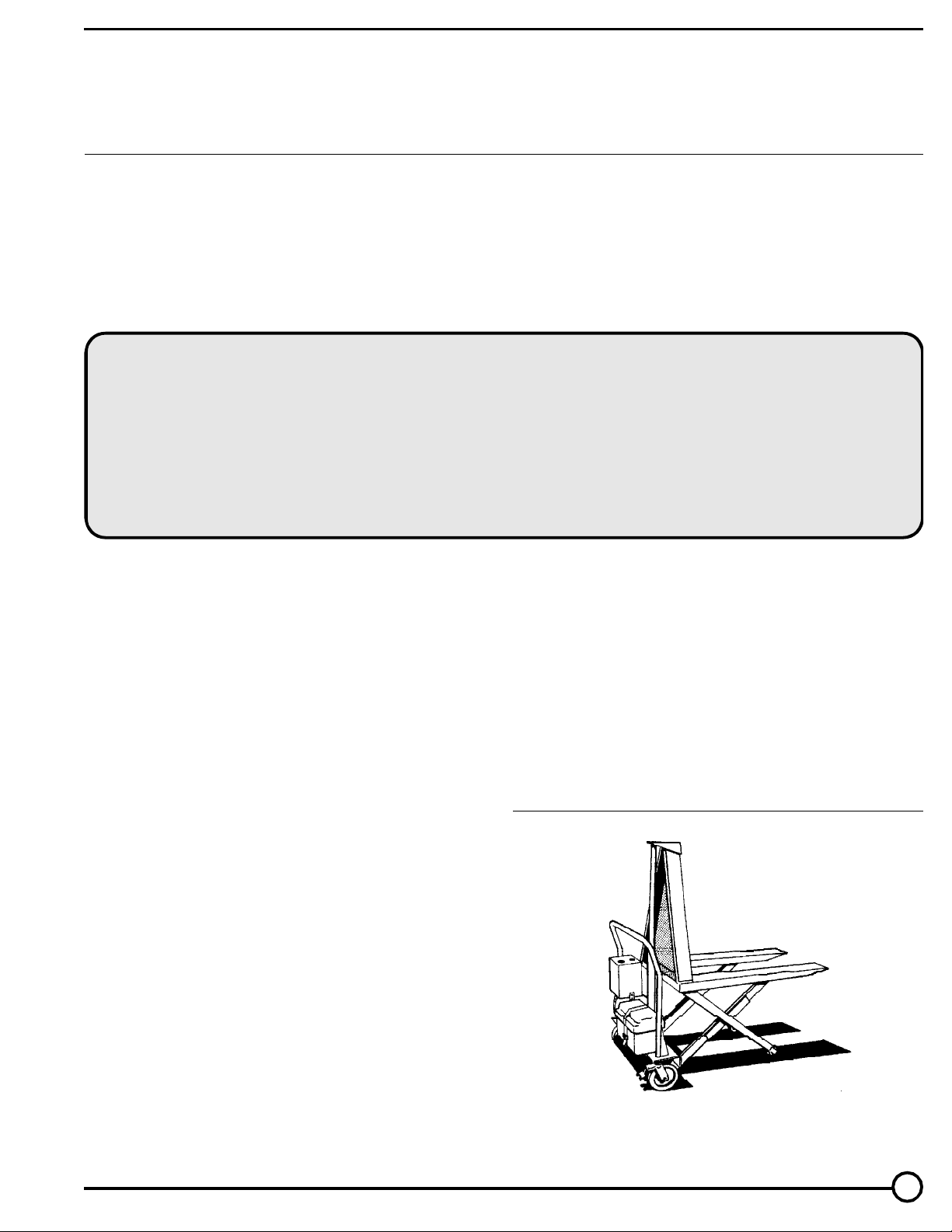
HIGH RISE LIFT • MODEL HIPM
Exploded Parts Drawing ......................................10
Parts Identification ...............................................11
Periodic Maintenance Instructions .......................12
Foot Pump Operation...........................................13
Warning Label Identification .................................14
Warranty..............................................................15
WARNINGS & SAFETY INSTRUCTIONS
Read owner's manual completely before operating unit!
• Not a personnel lift.
• Never go under forks if there is weight on unit.
• Remove weight & disconnect power before working on
unit.
• Use only maintenance parts supplied or approved by the
manufacturer.
• Do not change pressure relief valve setting.
• Do not clamp hydraulic cylinder in a vise as you may
distort the barrel.
• Never operate the lift unless you are watching it.
• Do not go near leaks - High pressure oil easily punctures
skin causing serious injury, gangrene, or death.
• Load tight agianst the bulkhead within the rated capcity.
• Transport loads in the lowered position only.
• Do not continue to operate the UP control if unit is not
raising.
• Relieve system pressure by operating the DOWN control
after the unit has come to rest.
• Consult factory before adding or performing any
modification to the original equipment.
• Do not use brake fluids or jack oils. Use AW-32 Hydraulic
oil or equal.
• Make sure all operator safety labels and guards are
in place.
damage during transit. If you see damage when unloading
make a note of it on the SHIPPER RECEIVER.
Remove all packing and strapping material, inspect
for damage. IF DAMAGE IS EVIDENT, FILE A CLAIM
WITH THE CARRIER IMMEDIATLY! Also, check the unit
size, type of power unit, etc., to ensure the unit is correct
for the intended application.
SERIAL NUMBER AND CAPACITY
The serial number and capacity is inscribed on the
nameplate (See p. 14 for location). Please remember to
include these numbers in any correspondence with your dealer
or the factory.
RECEIVING INSTRUCTIONS
Every unit is thoroughly tested and inspected prior
to shipment. However, it is possible that the unit may incur
HIGH RISE LIFT
MODEL HIPM
1
Page 2

LOADING INSTRUCTIONS
The load capacity rating as inscribed on the
nameplate of your unit designates the net capacity
for an evenly distributed load. This capacity must
never be exceeded, as permanent damage or
injury may result.
3.) Lift may only be used be used by authorized
personnel. All lift operators must have read
and understood all operating procedures
and safety guidelines in this Owner's Manual.
4.) Lift must never be overloaded.
When loading the lift always follow these guidelines:
1.) Always load tightly agianst the bulkhead.
2.) Transport loads in the lowered position only.
OPERATING INSTRUCTIONS
The High Rise Lift is furnished with a constant pressure rocker switch control as standard
equipment.
In order to operate the unit, pressure must
be maintained in the UP or Down position to raise
or lower the forks. On releasing either button, the
forks will remain in that particular position until the
switch is depressed again.
Responsibilities of Owners/Users
It is the responsibility of the owner/user for
the following:
5.) Operator must ensure that all safety
features of the lift are functioning properly
before each use.
6.) Any modifications to the lift must be
approved in writing by the manufacturer.
ORDERING REPLACEMENT OR EXTRA PARTS
Our company takes pride in using the finest
available parts for our equipment. We are not
responsible for equipment failure resulting from the
use of unapproved replacement parts. To order
replacement or extra parts for your equipment
contact Customer Service at the factory. In any
correspondence with the factory please include the
Serial Number which is inscribed on the nameplate
of the piece of equipment. Use only the part
numbers provided in this Owner's Manual. When
ordering parts for AC power units please indicate
the motor phase and voltage that the equipment is
operating on.
1.) The lift must be inspected and maintained in
accordance with the guidelines in this
manual.
2.) Any lift not in safe operating condition must
be removed from service until it is returned
to proper operating condition.
Unsafe condition may include, but is not
limited to the following : excessive hydraulic or air
leakage, missing rollers, pins, or fasteners, any
cracked or deformed structural members, cut or
frayed hydraulic, electric or air lines, and damaged controls or safety devices.
All repairs and maintenance must be per-
formed by qualified personnel.
2
Page 3
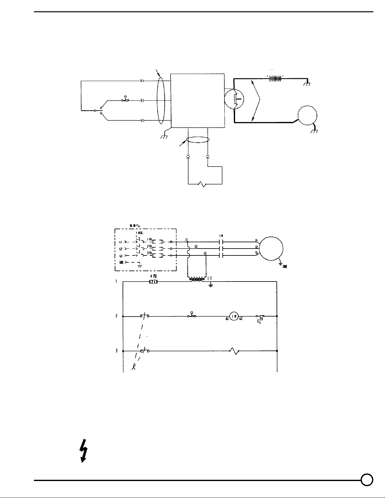
ELECTRICAL SCHEMATIC
blk
ROCKER
SWITCH
RAISE
LOWER
RAISED
brn
blu
blk
Pigtail
12
VDC
DC, MOTOR START
SWITCH AND
LOW-VOLTAGE CUT-OFF
VOLTAGE
yel blk
Pigtail
1 SOL H
N.C.
LOWERING
VALVE
12 VDC
(DEEP CYCLE)
1 M
#4 WELDING CABLE
1 MTR
1 MTR
red
1 PB
RAISE
red whi blk
1 LS
PLATFORM RAISED
1 SOL H
blk whiorg
1MTR
T'STAT
N.C. PLATFORM
LOWERING VALVE
BE SURE ALL POWER IS OFF BEFORE ATTEMPTING TO WORK ON THIS EQUIPMENT!
CAUTION: SERVICE WORK SHOULD BE PERFORMED ONLY BY TRAINED & QUALIFIED PERSONNEL
3
Page 4

Operating Instructions for Optional Bench Top Style Battery Charger
(for DC models equipped with our Bench Top Charger)
WARNING!
Working with or near lead acid batteries is dangerous.
Batteries contain sulfuric acid and produce explosive gases.
A battery explosion could result in loss of eyesight or serious
burns.
Do not smoke or allow a spark or flame near batteries.
Charge batteries in locations which are clean, dry, and well
ventilated. Do not lay tools or anything metallic on top of any
battery. All repairs to a battery must be made by experienced
and qualified personnel.
When working with batteries, remove personal items
such as rings, bracelets, necklaces, and watches. A battery
can produce enough voltage to weld jewelry to metal causing
a severe burn.
Always have plenty of fresh water and soap nearby in
case battery acid contacts skin, clothing, or eyes.
Operating the battery with a low battery voltage can
cause premature motor contact failure.
Do's and Don'ts
DO NOT leave charger connected for an indefinite length
of time.
DO NOT smoke, strike a match or cause a spark in the
vicinity of battery during charging.
DO make sure all battery connections are tight and clean.
DO NOT expose to rain or adverse conditions.
DO replace defective cords and wires immediately.
DO locate charger at least 24" above floor while charging.
DO NOT overcharge battery (manual position only)
OPERATING INSTRUCTIONS
Even if you did not purchase an optional battery
charger, your new High Rise Lift Truck has been fitted with
a matching plug which will connect directly to the Bench
Top Charger we offer. Contact your distributor if you wish
to purchase a battery charger.
4
Page 5

Operating Instructions for Standard On Board Style Battery Charger
(for DC models equipped with our On Board Charger)
WARNING!
Working with or near lead acid batteries is dangerous.
Batteries contain sulfuric acid and produce explosive
gases. A battery explosion could result in loss of eyesight
or serious burns.
Do not smoke or allow a spark or flame near batteries. Charge batteries in locations which are clean, dry,
and well ventilated. Do not lay tools or anything metallic
on top of any battery. All repairs to a battery must be
made by experienced and qualified personnel.
When working with batteries, remove personal items
such as rings, bracelets, necklaces, and watches. A
battery can produce enough voltage to weld jewelry to
metal causing a severe burn.
Always have plenty of fresh water and soap nearby in
case battery acid contacts skin, clothing, or eyes.
Operating the battery with a low battery voltage can
cause premature motor contact failure.
Our On Board charger is equipped with an external
ground wire (small green). During installation the charger
must be grounded to the equipment which it is connected
to. Be sure this wire is always connected to the chassis,
frame, or other metallic surface considered to be ground.
OPERATING INSTRUCTIONS
1.) Plug charger into a receptacle known to have
approximately 115V and 60 Hz. If an extension cord
must be used, keep it short and as large as possible.
A small cord will decrease the output of the charger
due to the voltage drop in the line. This will increase
the charging time.
ADDITIONAL INFORMATION
The On Board charger is current limited and will not
exceed its rated output, even if loads are placed on the
battery while the battery is charging.
The On Board chargers fuse will blow if the charger is
connected in reverse polarity
TROUBLESHOOTING
1) Make sure battery connections are electrically and
mechanically sound.
2) Check AC source for power.
3) Check fuse. Replace only with a fuse having the
same rating as originally supplied.
4.) Check battery condition. A highly sulfated battery
may take some time before current begins to flow
through it.
DO'S AND DON'TS
DO NOT leave charger connected for an indefinite length
of time.
DO NOT smoke, strike a match or cause a spark in the
vicinity of battery during charging.
DO make sure all battery connections are tight and clean.
DO NOT expose to rain or adverse conditions.
DO replace defective cords and wires immediately.
2.) When properly connected, the charge LED will
indicate the status of charge current flowing to the
battery.
3.) With only the red LED lit, the charger is providing full
output to the battery.
With both the red and green LED's lit the charger is
"topping off" the battery.
When only the green LED is on, the unit is providing a
"float" or maintenance, charge.
4.) Remember to unplug the charger before moving
equipment. Failure to do so could cause damage to
cords, receptacles and other equipment.
5
Page 6

HYDRAULIC OPERATIONFOR AC/DE
When the operator wants to raise the unit, he/she depresses the UP button. This starts the electric motor
which turns the hydraulic pump. Oil from the reservoir is drawn in through the suction filter and into the pump.
The pump delivers pressurized oil through a check valve before it enters the cylinders.
The function of the check valve is to allow the oil to flow in one direction, (towards the cylinders), and prevents
the flow of oil back into the pump circuit when the pump stops running. This holds the oil in the cylinders and will
maintain any particular barrel elevation, for extended periods of time.
If the load is excessive, and the UP button is still depressed, excessive pressure will build up in the circuit
between the pump and the cylinders. This forces the relief valve to unseat allowing the pump flow to circulate to
the reservoir preventing hydraulic or structural damage.
When the operator desires to lower the unit, he/she depresses the DOWN button. This energizes the
lowering solenoid valve coil, unseating the poppet valve and allowing oil return from the cylinders through the
pressure-compensated flow control valve, to the reservoir.
Releasing the DOWN button will de-energize the solenoid, closing the valve poppet. This and the check
valve prevents the oil from returning to the reservoir and the cylinders will stop retracting. The unit will maintain
that particular elevation until the operator chooses to move it once again.
Cartridge Valves
The lowering valve, as discussed above, is of cartridge construction and is virtually maintenance-free.
If there is a faulty operation, check Trouble Shooting Section. To clean the cartridge valve, follow this procedure:
1.) WARNING! Lower forks completely before removing cartridge valve.
2.) Use a sharp object to push poppet in from the bottom to open the valve.
3.) Repeat several times while valve is immersed in kerosene or mineral spirits. Blow dry.
4.) Blow compressed air through valve while holding the valve open as described in step 2.
5.) Inspect "o" rings and the teflon washer. If either shows nicks, tears, or cuts, replace.
6.) Reinstall. The valve should be tightened to approximately 20 ft. lbs.
Velocity Fuse
There is a brass velocity fuse with a stainless steel spring in the base of each cylinder (Item 10). In the
event of a hydraulic hose or fitting failure, the platform starts to lower at a fast rate. As soon as the descent speed
exceeds the preset speed, the Velocity Fuse will shut off the oil flow and the platform will remain nearly stationary
until pressure is re-applied after repairs are done. This safety feature reduces the possibility of accidental
personal injury or damage to the table or contents. If air is introduced into the system, the velocity fuse can lock
up even though no failure has occurred. To reset the velocity fuse just activate the pump by jogging the UP button.
Remove the load and cycle the unit several times to purge air.
6
Page 7

Air Bleed Procedure
If the forks descend very slowly or will not descend at all, air is likely trapped in the hydraulic circuit and must be bled from the system. The High Rise Lift Truck utilizes a bleeder screw at the top of
the cylinder. To bleed air from the hydraulic circuit, follow these directions.
1.) Loosen the bleeder screw at the to of the cylinder approximately 1/4 to 1/2 turn to allow trapped
air to escape. Depressed the foot pump treadle or job the motor to push the out of the system.
2.) When the cylinder is free of air only clear hydraulic fluid will be visible at the bleeder screw. Tighten
the hose fitting.
HYDRAULIC SCHEMATIC
1 MTR.
1.5" X 18" DISPLACEMENT
CYLINDER W/INTERNAL
VELOCITY FUSE
HYD.
PUMP
SUCTION
FILTER
LC/TC
PRESSURE
CHECK VALVE
ADJ. PRESSURE
RELIEF VALVE
100 Micron
LOWERING VALVE
PRESS. COMPENSATED
FLOW CONTROL
RETURN
FILTER
10 Micron
LC/TC
LY/FC
TWO-SPEED
FOOT PUMP
PRESSURE
CHECK VALVE
1.5" x 18" DISPLACEMENT CYLINDER
W/INTERNAL VELOCITY FUSE
PRESS. COMPENSATED
PRESSURE
CHECK VALVE
ADJ. PRESSURE
RELIEF VALVE
FLOW CONTROL
LOWERING VALVE
1 GPM
ELECTRIC POWER UNIT
HYDRAULIC DIAGRAM
MANUAL FOOT PUMP
HYDRAULIC DIAGRAM
7
Page 8

HYDRAULIC EQUIPMENT
Trouble Shooting Quick Reference Guide
(For further information contact the factory)
1.) Forks do not raise but pump is running or
humming.
Possible Cause
a. Voltage at motor terminals may be too low
to run pump at existing load.
b. Hose or hydraulic line is leaking.
c. Fluid level in reservoir is low.
d. Load exceeds capacity requirements. Relief
Valve is bypassing the fluid back into the
reservoir.
e. Suction filter is clogged, starving pump.
f. Suction line may be leaking air, due to loose
fittings.
g. Filler/Breather cap on tank may be clogged.
h. Down Valve may be energized by faulty
wiring or stuck open.
i. Hydraulic pump may be inoperative.
RemedyObservation
a. Measure voltage at motor terminals or as
near as possible, while pump is running
under load. If voltage is sufficient, check for
inadequate or incorrect wiring as this can
starve the motor. (Refer to chart in Owner's
Manual for recommendations.) Correct as
necessary.
b. Correct as necessary.
c. Add fluid. Refer to Owner's Manual for
proper fluid levels.
d. DO NOT CHANGE RELIEF VALVE
SETTING. Instead, reduce the load to rated
capacity.
e. Remove and clean.
f. Inspect all fittings for proper fit.
g. Remove and clean.
h. Remove Solenoid Valve. Check and clean
(Refer to Hydraulic Section of Owner's
Manual p. 6).
i. Disconnect hydraulic line at power unit. Put
pressure line in a large container and cycle
pump. If no output, check the pump motor
coupling, which may be defective, and
correct as necessary. If pump is worn,
consult factory for replacement parts
service.
2.) Forks raise too slowly.
3.) Motor labors, or is excessively hot.
j. Low battery (DC units only).
a. Foreign material stuck in Down Solenoid,
causing some fluid to bypass back into tank.
b. Foreign material clogging suction filter,
breather cap, or a pinched hose.
c. Low motor voltage.
d. Table overloaded.
e. Pump is inoperative.
f. Low battery (DC units only).
a. Voltage may be low.
b. Incorrect wiring.
c. Oil starvation causes pump to bind. High
internal heat is developed. If this occurs,
pump may be permanently damaged.
d. Binding cylinders.
e. Low battery (DC units only).
j. Adequately charge battery before further
operation. (Refer to Charging Section of
Owner's Manual.)
a. Lower the forks. Remove the Solenoid
Valve and clean (Refer to Hydraulic Section
of Owner's Manual p.6).
b. Correct as necessary. (See also, 1(f), (h).
c. See 1(a).
d. See 1(e).
e. See 1(j).
f. Charge battery.
a. See 1(a).
b. Check that one leg of the motor lines is not
connected to ground.
c. See 1(d), (f), (g), (h), (j).
d. Align cylinders correctly.
e. Charge battery.
8
Page 9

Possible CauseObservation
Remedy
4.) "Spongy" or "Jerky" table operation. Do not
confuse spongy operation with small surges
caused by foreign material on table wheel
roller plate.
5.) Forks lower too slowly when loaded.
6.) Forks lower too quickly.
7.) Forks raise then lower slowly.
a. Fluid starvation.
b. Air is trapped in cylinder.
a. Down Valve filter clogged.
b. Pinched tube or hose.
c. Foreign material in Flow Control Valve.
d. Binding cylinders
e. Foreign material in Velocity Fuse.
a. Leaking hoses and/or cracked fittings.
b. Check valve is stuck open.
c. Foreign material stuck in Flow Control
Valve.
a. Down Solenoid Valve may be incorrectly
wired or is stuck open due to dirt.
a. See 1(d), (f), (g), (j).
b. See air bleed procedure on p.7.
a. Remove Solenoid Valve and clean filter.
b. Correct as necessary.
c. Remove and clean Flow Control Valve.
(Refer to Hydraulic Section of Owner's
Manual p. 6).
d. Align cylinders correctly.
e. Remove and clean Velocity Fuse. (Refer to
Hydraulic Section of Owner's Manual p. 6).
a. Correct as necessary.
b. Remove and clean Check Valve. (Refer to
Hydraulic Section of Owner's Manual p. 6).
c. Remove Flow Control Valve from the Valve
Block and clean. (Refer to Hydraulic Section
of Owner's Manual p. 6).
a. See 2(a).
8.) Forks raise, but do not lower.
b. Check Valve may be stuck open.
c. Check for leaking hoses, fittings, pipes.
d. Cylinder packings may be worn or
damaged.
a. Incorrect Down Solenoid Valve wiring.
b. Down Solenoid Valve is stuck.
c. Faulty Down Solenoid Coil.
d. Object blocking down travel.
e. Binding cylinders.
f. In case of excessive down speeds, the
Velocity Fuse will become operative and
shut off the oil flow from the cylinders, thus
the platform will remain stationary.
b. Remove and clean Check Valve. (Refer to
Hydraulic Section of Owner's Manual.)
c. Correct as necessary.
d. Replace packings.
a. Correct as necessary. (Refer to Electrical
Section of Owner's Manual.)
b. Lightly tap down the Solenoid Coil body to
seat it properly. (DO NOT hit coil hard as it
will permanently damage the internal stem).
DO NOT remove the Solenoid Valve from
the Block as the unit will come down at a
dangerous speed.
c. Remove and replace. (Refer to Electrical
Section of Owner's Manual.
d. Raise forks and remove the object blocking
the down travel, then press the down
button.
e. See 2(e).
f. To unlock, re-pressurize the hydraulic
system.
9.) Erratic or uncontrolled operation.
g. Check if the Limit Switch is inoperative and
the platform has raised all the way so that
the mechanical stops are engaged. If
mechanical stops are engaged, the Velocity
Fuse has been locked up.
a. Low battery (DC units only).
g. Refer to Velocity Fuse Section of the
Owner's Manual.
a. Charge battery.
9
Page 10

EXPLODED PARTS DRAWING
High Rise Lift • Model HIPM
38
23
22
23
22
35
36
44
39
26
25
45
40
25
26
28
41
2
3
1
8
7
6
16
17
18
15
4
8
10
9
37
33
27
34
20
23
22
24
21
17
19
5
11
12
13
14
10
Page 11

PARTS IDENTIFICATION - High Rise LIft • Model HIPM
KIT NO.
D
D
C,D
C
C
B
B
A
A
A
A
A
ITEM NO.
1
2
3
4
5
6
7
8
9
10
11
12
13
14
15
16
17
18
19
20
21
22
23
24
25
26
27
28
33
34
35
36
37
38
39
39A
39B
39C
39D
40
41
44
45
A
B
C
D
E
DESCRIPTION
Hydraulic cylinder (1-½ x 28)
3/8" x 1" hex head cap screw
3/8" split lock washer
Inner leg
Outer leg
Inner leg roller
Inner leg roller pin
3/4" clip ring
Outer leg roller
Outer leg roller pin
3/4" clip ring
3/4" x 18 ga. machinery bushing
- narrow rim
Outer leg hinge bearing
Outer leg hinge pin
1" x 18 ga. machinery bushing
- narrow rim
Axle pin bearing
1" x 18 ga. machinery bushing
- narrow rim
1" clip ring
3/4" clip ring
Floor lock
Inner leg hinge pin bearing
3/8-16 nylon insert lock nut
3/8" USS flat washer
Swivel caster
(add a "-B" for caster with brake)
3/8-16 x 1-¼" hex head cap screw
3/8" USS flat washer
5/16-18 nylon nut
5/16" USS flat washer
Battery box (includes lid)
Battery (SHIPS VIA TRUCK ONLY)
¼"-20 x 1-¼" slotted head screw
¼" I.D. fender washer
Battery box strap
(included with battery)
Hydraulic reservoir
DC Motor / pump assembly
DC motor only
Hydraulic pump only
Motor start solenoid
Cartridge valve assembly
3/8-16 x 1" self drill and tap screw
3/8-16 x 1" hex head cap screw
Power unit shroud
Raise / lower control switch
Caster kit
(includes items 22-26)
Bearing kit (includes items 16,21)
Outer roller kit (includes items 8-10)
Inner roller kit (includes items 6-8)
Cylinder seal repair kit (includes all seals for repair)
ENGINEER NO.
15-021-006
n/a
n/a
15-010-005
15-010-006
16-132-001
15-112-008
n/a
16-132-001
01-112-008
n/a
n/a
01-111-007
05-112-006
n/a
01-111-006
n/a
n/a
n/a
16-132-080
01-111-007
n/a
n/a
16-132-034
n/a
n/a
n/a
n/a
15-139-002
15-139-001
n/a
n/a
n/a
15-023-001
15-137-001
01-135-041
01-143-015
01-034-026
01-153-009
n/a
n/a
15-024-006
15-022-006
15-022-006
15-154-012
15-154-013
15-154-014
15-154-015
PART NO.
HIPM-CYL
n/a
n/a
HIPM-INLG
HIPM-OTLG
HIPM-ILG-RLR
HIPM-ILG-RP
n/a
HIPM-OLG-RLR
HIPM-OLG-RP
n/a
n/a
HIPM-OLG-HB
HIPM-OLG-HP
n/a
HIPM-APB
n/a
n/a
n/a
HIPM-FLK
HIPM-ILG-BG
n/a
n/a
HIPM-CST-S
n/a
n/a
n/a
n/a
HIPM-BTBX
HIPM-BT
n/a
n/a
HIPM-BTBX-ST
HIPM-RES
HIPM-DCPU
HIPM-MTR
HIPM-PMP
HIPM-SOL
HIPM-CVA
n/a
n/a
HIPM-PU-S
HIPM-CS
HIPM-KIT-A
HIPM-KIT-B
HIPM-KIT-C
HIPM-KIT-D
HIPM-KIT-E
QTY.
1
1
1
2
2
4
4
2
4
2
4
4
2
2
2
2
2
2
2
2
2
8
8
2
8
8
2
2
1
1
2
2
1
1
1
1
1
1
1
2
2
1
1
1
1
1
1
1
a/k Available only with purchase of kit
n/a Not Available
11
Page 12

PERIODIC MAINTENANCE INSTRUCTIONS
WARNING! REMOVE LOAD AND COMPLETELY LOWER FORKS BEFORE PERFROMING ANY MAINTENANCE.
(A) Before Each Use Check For The Following :
1.) Frayed wires (Powered models only)
2.) Oil leaks
3.) Proper caster operation
4.) Pinched or chafed hoses, loose fittings
5.) Structural deformation of forks or frame
6.) Unusual noise or binding
Do not use if there are any of the above!
(B) Monthly Inspections
1.) Check oil level. Oil should be 1" to 1-1/2" below the top of the tank with
the lift in the fully lowered position. Add as necessary.
2.) Check for oil leaks. See Trouble Shooting Section and correct
as necessary.
3.) Check water level in battery. (DC models only)
4.) Check clevis and pivot points for wear.
5.) Check for worn or damaged hydraulic hoses, electrical wires, and cords.
Repair as necessary.
6.) Check rollers for looseness and wear. See Trouble Shooting.
7.) Check retaining rings at load rollers and clevis.
8.) Check for unusual noise. See Trouble Shooting section.
9.) Make sure all warning labels are in place and in good condition.
10.) Clean off dirt and debris.
(C) Yearly Inspection
12
Hydraulic oil should be changed at least once a year, or sooner if the
oil darkens or becomes gritty. Flush reservoir before refilling. Presence of
water is indicated if the oil turns milky. Recommended oil: Purity ISO AW-32
Hydraulic fluid or equal.
All maintenance work must be performed by qualified personnel with
training in the repair of electrical and hydraulic components.
Page 13

Operating Instructions for Two-speed Hydraulic Foot Pump
Features:
Your new lift equipment has been supplied with an exclusive two-speed foot pump. The internal features of your pump
include a primary pressure relief valve, pressure compensated return flow control valve, and an integrated lowering
valve.
Replaceable bushings, valve components, and seals have been utilized in the construction of the pump in the event
that replacements are necessary.
Operating Instructions:
Stay clear of moving parts. The platform will rise as the foot pedal is pumped. Depressing the release lever will lower
the table at a controlled rate of descent.
In the event the platform has been overloaded, the pressure relief will open because of excessive pressure build-up
in the hydraulic system. Oil will bypass into the reservoir. Never change the pressure relief setting. Do not exceed
the rated capacity of your lift equipment.
Speed Selection for Two-speed Pumps:
This pump offers two "speeds". The low speed produces low volume/high pressure. The high speed produces high
volume/low pressure. The operator has the option of selecting the optimum pump speed for the application at hand.
Pump speeds are selected by sliding the "lock collar"(See item # 2A on the parts identification) in
drop of oil will keep the collar working freely.
or out. An occasional
Air Bleed Procedure:
Whether your pump is a new installation, or has been recently serviced, air has likely entered the hydraulic
system. The design of this pump includes an "air bleed screw" which will aid in the removal of unwanted air from
the foot pump area of the hydraulic system. Use the following steps to remove this air from the system.
1) Check all fittings to be sure they are tight. Ensure that the oil is filled to within 1" of the top of the reservoir
when the lift is in the fully lowered position.
2) Locate the "air bleed screw"( See item # 33 on the pump body) and loosen appoximately 1/2 turn
couterclockwise. As soon as you have loosened the screw, slowly depress the foot pedal. This will force the air
out of the pump chamber. Before you let the pump pedal return to the "up" or "home" position, tighten the air
bleed screw. This will prevent air form re-entering the pump chamber. Repeat the above procedure until the
pump chamber is completely filled with oil and a "spongy" feel is no longer present. If the air bleeding procedure
has been successful, the feel of the pump pedal will be firm and the complete stroke of the pump will produce
fluid flow.
LOCK COLLAR
PRESSURE
CHECK
VALVE
2 SPEED
FOOT PUMP
PRESSURE
CHECK VALVE
ADJ. PRESSURE
RELIEF VALVE
LOWERING
VALVE
PRESS. COMPENSATED
FLOW CONTROL 1 GPM
TO CYLINDER
AIR BLEED SCREW
LOWERING VALVE
PRESSURE RELIEF VALVE
13
Page 14

WARNING LABEL IDENTIFICATION
MAKE SURE ALL WARNING LABELS ARE IN PLACE!
1
UP
4
KEEP CLEAR
WHEN
Located on Reservoir
3
OPERATING
DOWN
5
2
1
DANGER
CORROSIVE
MATERIAL
2
PELIGRO
MATERIAL
CORROSIVO
DANGER
MATIÈRES
CORROSIVES
*Product safety signs or labels should be
periodically inspected and cleaned by the
product users as necessary to maintain
good legibility for safe viewing distance . . .
ANSI 535.4 (10.21)
Contact manufacturer for replacement labels if needed.
5
KEEP CLEAR OF
PINCH POINT
3
HYDRAULIC OIL OR EQUIVALENT
ACEITE HIDRÁULICO O EQUIVALENTE
HUILE HYDRAULIQUE AW-32 OU ÉQUIVALENT
4
WARNING
!
KEEP CLEAR
WHEN IN USE
MANTENGASE ALEJADO DE
ALEJADO CUANDO
SE ESTA OPERANDO
PUNTO DE CORTE
T & S Equipment Company
Ph (219)665-9521
Fax (219)665-1339
ISO AW-32
AVISO
!
MANTENGASE
! AVERTISSEMENT! WARNING ! AVISO
POINT DE PINCEMENT
SE TENIR À DISTANCE DU
AVERTISSEMENT
!
SE TENIR À DISTANCE
FONCTIONNEMENT
295
206
LORS DU
220
208
14
Page 15

LIMITED WARRANTY
covered unless done at manufacturer’s facilities. Any modifications performed without written approval
DISPOSITION. Our company will make a good faith effort for prompt correction or other
ONE YEAR LIMITED WARRANTY. The manufacturer warrants for the original purchaser against
defects in materials and workmanship under normal use one year after date of purchase. (Not to exceed
15 months after date of manufacture.) Any part which is determined by the manufacturer to be defective
in material or workmanship and returned to the factory, shipping costs prepaid, will be, as the exclusive
remedy, repaired or replaced at our option. Labor costs for warranty repairs and/or modifications are not
of the manufacturer may void warranty. This limited warranty gives purchaser specific legal rights which
vary from state to state.
LIMITATION OF LIABILITY. To the extent allowable under applicable law, the manufacturer’s
liability for consequential and incidental damages is expressly disclaimed.
The manufacturer’s liability in any event is limited to, and shall not exceed, the purchase price paid.
Misuse or modification may void warranty.
WARRANTY DISCLAIMER. Our company has made a diligent effort to illustrate and describe the
products shown accurately; however, such illustrations and descriptions are for the sole purpose of
identification, and do not express or imply a warranty that the products are merchantable, or fit for a
particular purpose, or that the products will necessarily conform to the illustrations or descriptions.
The provisions of the warranty shall be construed and enforced in accordance with the UNIFORM
COMMERCIAL CODE and laws as enacted in the State of Indiana.
adjustment with respect to any product which proves to be defective within the Limited Warranty.
Warranty claims must be made in writing within said year.
SERVICE RECORD
DATE OF SERVICE:_____/_____/_____
WORK DONE BY:______________________________
SERVICE PERFORMED:__________________________________
_______________________________________________________
_______________________________________________________
DATE OF SERVICE:_____/_____/_____
WORK DONE BY:______________________________
SERVICE PERFORMED:__________________________________
_______________________________________________________
_______________________________________________________
DATE OF SERVICE:_____/_____/_____
WORK DONE BY:______________________________
SERVICE PERFORMED:__________________________________
_______________________________________________________
_______________________________________________________
DATE OF SERVICE:_____/_____/_____
WORK DONE BY:______________________________
SERVICE PERFORMED:__________________________________
_______________________________________________________
_______________________________________________________
DATE OF SERVICE:_____/_____/_____
WORK DONE BY:______________________________
SERVICE PERFORMED:__________________________________
_______________________________________________________
_______________________________________________________
DATE OF SERVICE:_____/_____/_____
WORK DONE BY:______________________________
SERVICE PERFORMED:__________________________________
_______________________________________________________
_______________________________________________________
15
 Loading...