

Page 1
Vestil Manufacturing Corporation
2999 North Wayne St., Angola, IN 46703
Phone (260) 665-7586 • Fax (260) 665-1339
E-mail: sales@vestil.com • www.vestil.com
Contents
Warnings and Safety Instructions .....................1
Receiving Instructions .......................................1
Loading Instructions ..........................................2
Operating Instructions .......................................2
Installation Instructions......................................2
Periodic Maintenance Instructions ....................3
Electric Schematic.............................................7
Power Conversion ......................................... 8-9
Revised 09-01
A company dedicated to solving ergonomic and material handling
problems since 1953
.
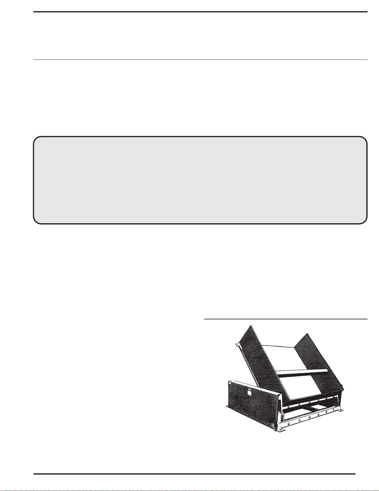
OWNER'S
MANUAL
GROUND LIFT TILTER
MODEL GLT-4000
Hydraulic Operation and Schematic.............. 7-8
Exploded Parts Drawing .................................... 9
Parts Identification........................................... 10
Trouble Shooting Guide ............................ 11-12
Warning Label Identification ............................13
Material Safety Data Sheets ..................... 14-15
Warranty..........................................................16
Service Record................................................16
WARNINGS & SAFETY INSTRUCTIONS
Read owner's manual completely before operating unit!
• Not a personnel lift.
• Never go under platform if there is weight on unit.
• Remove weight & disconnect power before working on
unit.
• Use only maintenance parts supplied or approved by the
manufacturer.
• Do not change pressure relief valve setting.
• Do not clamp hydraulic cylinder in a vise as you may
distort the barrel.
• Never operate the lift unless you are watching it.
• Load the lift as uniformly as possible.
• Consult the factory for uneven loading.
• Do not continue to operate the UP control if unit is not
raising.
• Relieve system pressure by operating the DOWN
control after the unit has come to rest.
• Consult factory if adding or performing any
modification to the original equipment.
• Do not use brake fluids or jack oils. Use AW 32
Hydraulic oil or equal.
• Make sure all operator safety labels (
guards are in place.
see p. 16
) and
Remove all packing and strapping material,
inspect for damage. IF DAMAGE IS EVIDENT, FILE A
CLAIM WITH THE CARRIER IMMEDIATLY! Also, check
the unit size, type of power unit, etc., to ensure the unit is
correct for the intended application.
SERIAL NUMBER AND CAPACITY
The serial number and capacity are inscribed on the
nameplate (
include these numbers in any correspondence with your
dealer or the factory.
See p. 16 for location
). Please remember to
RECEIVING INSTRUCTIONS
Every unit is thoroughly tested and inspected prior
to shipment. However, it is possible that the unit may incur
damage during transit. If you see damage when unloading
make a note of it on the SHIPPER RECEIVER.
Ground Lift Tilter
Model GLT-4000
1
Page 2

LOADING INSTRUCTIONS
The load capacity rating as inscribed on the nameplate of
your unit designates the net capacity for an evenly distributed
load. This capacity must never be exceeded, as permanent
damage or injury may result.
When loading the lift always follow these guidelines:
1.) Always place the load firmly against the restraint lip.
2.) Lower the load
gently
on to the platform.
OPERATING INSTRUCTIONS
The
Ground Lift Tilter
hand held push button control as standard equipment. In
order to operate the unit, pressure must be maintained on the
UP or Down button to raise or lower the
releasing either button, the deck will remain in that particular
position until the Up or Down button is depressed again.
is furnished with a constant pressure
Ground Lift Tilter
. On
RESPONSIBILITIES OF OWNERS/USERS
It is the responsibility of the owner/user for the following:
1.) The lift must be inspected and maintained in
accordance with the guidelines in this manual.
2.) Any lift not in safe operating condition must be removed
from service until it is returned to proper operating condition.
Unsafe condition may include, but is not limited to the
following :
pins, or fasteners, any cracked or deformed structural
members, cut or frayed hydraulic, electric or air lines, and
damaged controls or safety devices.
excessive hydraulic or air leakage, missing rollers,
INSTALLATION INSTRUCTIONS
Review Complete Owner's Manual Before
Commencing Installation.
For installation you will need the following:
1.) A fork truck or hoisting means.
2.) Lag bolts, masonry drill, masonry bit, wrench for lag bolt,
grout, and steel shims.
3.) An adequate circuit with the specified voltage, including
fuses and disconnect or circuit breakers.
Reference NFPA 70 (NEC).
4.) Minimize voltage drop by using adequate wire size.
Reference NFPA 70 (NEC).
WARNING! ONLY INSTALL LIFT ON A
STABLE MOUNTING SURFACE.
Move the lift with straps or forks under frame.
Read all the warning labels on the lift and be sure all of the
labels on page 16 are on the lift.
The lift must be securely anchored to the floor before use
(
Except those that are designed to be portable
Check local codes pertaining to your application.
If the power unit is to be mounted externally and has been
shipped separately, blow out the connecting hydraulic line
with compressed air to be sure it is clear before connecting to
the power unit.
Be sure maintenance stop is locked in place before getting
under platform.
).
All repairs and maintenance must be performed by qualified
personnel.
3.) Lift may only be used be used by authorized personnel. All
lift operators must have read and understood all operating
procedures and safety guidelines in this Owner's Manual.
4.) Lift must never be overloaded.
5.) Operator must ensure that all safety features of the lift are
functioning properly before each use..
6.) Any modifications to the lift must be approved in writing by
the manufacturer.
For additional information refer to ANSI National Standard for
Industrial Scissor Lifts (ANSI MH29.1-1994)
After anchoring to floor, shim or grout the full length on the
frame sides.
The entire length of the frame sides must be supported.
Connect power source as shown in electrical section. You
must be a qualified electrician to do the hookup.
Operate lift through a few cycles. Check and add oil if
necessary. See oil specification on page 5.
Clean up any debris or spilled oil.
ORDERING REPLACEMENT OR EXTRA PARTS
Our company takes pride in using the finest available parts
for our equipment. We are not responsible for equipment
failure resulting from the use of unapproved replacement
parts. To order replacement or extra parts for your equipment
contact Customer Service at the factory. In any correspondence with the factory please include the Serial Number
which is inscribed on the nameplate of the piece of equipment.
Use only the part numbers provided in this Owner's Manual.
When ordering parts for AC power units please indicate the
motor phase and voltage that the equipment is operating on.
2
Page 3

PERIODIC MAINTENANCE INSTRUCTIONS
WARNING! BEFORE PERFORMING ANY MAINTENANCE WORK ALWAYS UNLOAD LIFT AND INSTALL MAINTENANCE SAFETY STOP(S)
(A) Before Each Use Check For The Following :
1.) Frayed wires, damaged components
2.) Oil leaks
3.) Pinched or chafed hoses, loose fittings
4.) Structural deformation of platform or frame
5.) Unusual noise or binding
Do not use if there are any of the above!
(B) Monthly Inspections
1.) Check oil level. Oil should be 1" to 1-1/2" below the top of the tank with
the lift in the fully lowered position. Add as necessary.
2.) Check for oil leaks. See Trouble Shooting Section and correct
as necessary.
3.) Check pins and pivot points for wear.
4.) Check for worn or damaged hydraulic hoses, electrical components, and cords.
Repair as necessary.
5.) Check rollers for looseness and wear. See Trouble Shooting.
6.) Check retaining rings at load rollers and pins.
7.) Check for unusual noise. See Trouble Shooting section.
8.) Make sure all warning labels are in place and in good condition.
9.) Clean off dirt and debris.
(C) Yearly Inspection
Hydraulic oil should be changed at least once a year, or sooner if the
oil darkens or becomes gritty. Flush reservoir before refilling. Presence of
water is indicated if the oil turns milky. Recommended oil: AW-32 or H015d
hydraulic fluid Dexron Transmission fluid.
All maintenance work must be performed by qualified personnel with
training in the repair of electrical and hydraulic components.
3
Page 4
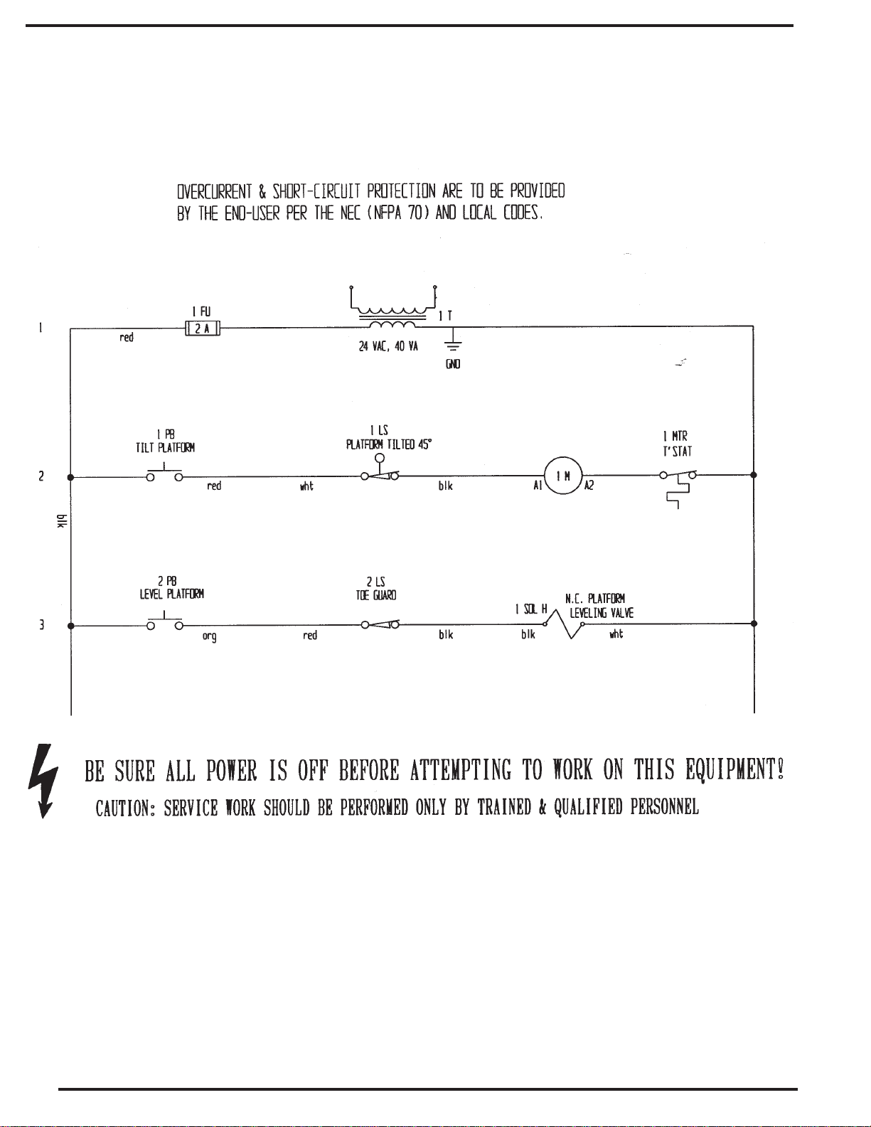
ELECTRICAL SCHEMATIC
4
Page 5
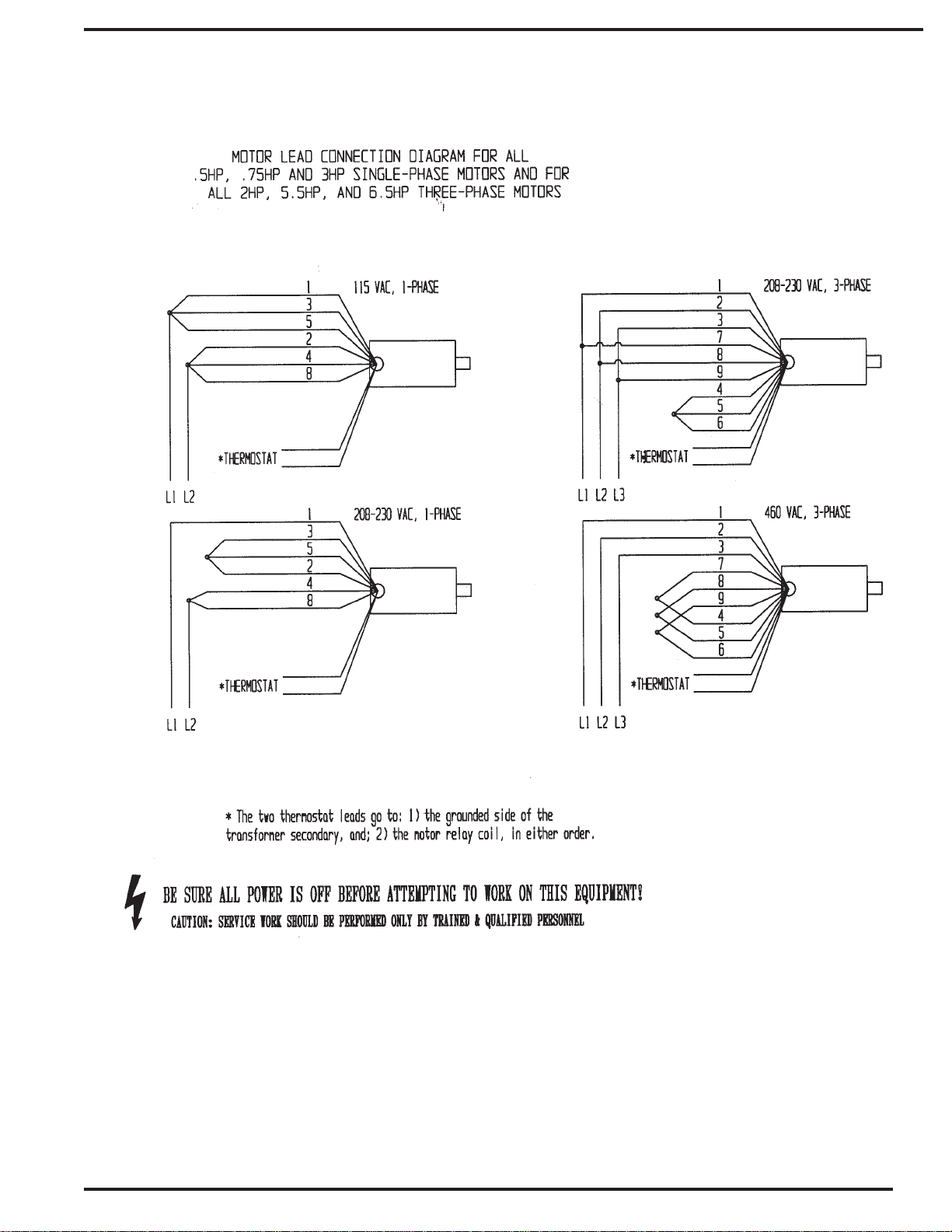
MOTOR VOLTAGE CONVERSION
5
Page 6

PRIMARY WIRING FOR CONTROL TRANSFORMER
6
Page 7

HYDRAULIC OPERATION
When the operator wants to raise the unit, he depresses the UP button. This starts the electric
motor (Item 3) which turns the hydraulic pump (Item 4). Oil from the reservoir (Item 1) is drawn in through
the suction filter (Item 2) and into the pump. The pump delivers the pressurized oil through the check valve
(Item 6) before entering the cylinders.
The function of the check valve is to allow the oil to flow in one direction, i.e. towards the cylinders.
It also prevents the flow of oil back into the pump circuit when the pump stops running. This holds the oil
in the cylinders and maintains the desired elevation.
If the load is excessive, and the UP button is still depressed, pressure will build up in the circuit
between the pump and the cylinders. This forces the relief valve (Item 5) to unseat allowing the pump flow
to return to the reservoir to preventing hydraulic or structural damage.
When the operator desires to lower the units, he depresses the DOWN button. This energizes the
down solenoid valve (Item 7). The poppet in the solenoid valve is unseated and oil now returns from the
cylinders through the return screen (Item 9), solenoid valve, flow control valve (Item 8), oil return hose,
and into the reservoir.
The pressure compensated flow control valve (Item 8) controls the down speed of the table. It is
preset and cannot be adjusted. Releasing the DOWN button will de-energize the solenoid, closing the
valve poppet. This prevents the oil from returning to the reservoir and the cylinders will stop retracting.
The unit is now maintained at that particular elevation.
CARTRIDGE VALVES
The lowering valve, as discussed above, is of cartridge construction and is virtually
maintenance-free. If there is a faulty operation, check Trouble Shooting Section. To clean the
cartridge valve, follow this procedure:
1.) WARNING: remove load and support weight of the table with maintenance stop(s)
before removing cartridge valve.
2.) Use a sharp object and push poppet in from the bottom to open the valve.
3.) Repeat several times while valve is immersed in kerosene or mineral spirits. Blow dry.
4.) Blow compressed air through valve while holding open as descibed in step 2.
5.) Inspect "O" rings and the teflon extrusion washer.
6.) Reinstall. The valve should be tightened to approximately 30 ft. lbs.
VELOCITY FUSE
There is a brass velocity fuse with a stainless steel spring in the base of each cylinder (Item 10). In
the event of a hydraulic hose or fitting failure, the platform starts to lower at a fast rate. As soon as the descent
speed exceeds the preset speed, the Velocity Fuse will shut off the oil flow and the platform will remain nearly
stationary until pressure is re-applied after repairs are done. This safety feature reduces the possibility of
accidental personal injury or damage to the table or contents. If air is introduced into the system, the velocity
fuse can lock up even though no failure has occurred. To reset the velocity fuse just activate pump by
depressing the UP button. Remove the load and cycle the unit several times to purge air.
7
Page 8

AIR BLEED PROCEDURE
If your unit descends very slowly or will not descend at all, air could be trapped in the hydraulic circuit
and must be "bled" from the system. If you experience the above, follow these directions.
1.) Completely lower the platform and remove the load.
2.) Remove one cylinder from its mounting points.
3.) Rotate the cylinder so that the end with the pressure hose connection is "up" or is higher than any other point
of the cylinder. This will allow the air to travel to a point in the cylinder where it can be expelled.
4.) Loosen the hose connection approximately 1/4 to 1/2 turn to allow trapped air to escape.
caution
Jogging the power unit will pressurize the hydraulic system, forcing trapped air from the cylinder.
5.) When the cylinder is free of air, tighten the hose connector fitting and reinstall the cylinder. Please note: The
cylinder is now likely to be too long to fit into the original mounting points. To collapse the cylinder depress the
DOWN button and manually force the cylinder back to its original length to install.
6.) Repeat procedure with other cylinder.
, you may need to "jog" the power unit slightly by quickly, momentarily depressing the UP button.
Using extreme
HYDRAULIC SCHEMATIC
8
Page 9

EXPLODED PARTS DRAWING
GROUND TILTER • GLT-4000
16
13
8
9
10
11
14, 15
12
2
3
1
7
6
3
4
1
5
6
9
Page 10

PARTS IDENTIFICATION
GROUND TILTER • GLT-4000
ITEM NO.
1
2
3
4
5
6
7
8
9
10
11
12
13
14
15
16
*17
*18
*19
*20
*21
*22
*23
*24
*25
*26
*27
*28
*29
*30
*31
*32
*33
*34
*35
*36
*37
*38
*39
*40
DESCRIPTION
Clevis Pin 1 x 3-1/4
Cylinder 2 x 8
Hair Pin Clip
Clevis Pin 1 x 2-1/4
Right Side Guard
Screw 5-1/6-18 x 1/2 Self Tapping
Plastic Guard 12 x 51
Machiner Screw 5/16-18 x 1-1/4
Toe Guard with Bevel
Fender Washer 5/16
Sensor Bracket
Lock Nut 5/16-18
Cross Bar
Toe Guard Bolt
Machine Screw 8-32 x 1/2
Left Side Guard
Motor Pump Combo, 1 phz Low
Motor Pump Combo, 1 phz High
Motor Pump Combo, 3 phz Low
Motor Pump Combo, 3 phz High
Coil Only 24 vac.
Control Transformer
Cartridge Valve with Coil
Cartridge Valve Only
Dust Cover
Foot Control
Hand Control
Hose Kit
Junction Box
Motor Contactor
Single Phz. Motor Low Speed
Single Phz. Motor High Speed
Three Phz. Motor Low Speed
Three Phz. Motor High Speed
Pump 0.6 Disp.
Pump 0.73 Disp.
Pump 0.122 Disp.
Pump 0.153 Disp.
Reservoir Breather Cap
Hydraulic Oil Reservoir
ENGINGEER NO.
2848
04-021-004
45286
10-433-10
04-024-016
32416
GLT-PLGD
27745
04-015-029
33214
04-016-021
37021
04-016-010
01-145-010
24189
04-024-017
GLT-MPA-1A
GLT-MPA-1B
GLT-MPA-3A
GLT-MPA-3B
6316024
01-129-001
SV08-20-S-O-N-24AG
SV08-20-S-O-N
GLT-PU-DC
01-522-012
01-522-015
GLT-HK
AB-664JS
E9.10-24AC
01-135-032
01-135-043
01-135-029
01-135-030
01-143-905
01-143-906
01-143-907
01-143-908
GLT-PU-RBC
GLT-PU-RES
PART NO.
GLT-CP-1
GLT-CYL
GLT-HPC
GLT-CP-2
GLT-RSG
GLT-SC
GLT-PLGD
GLT-BLT-1
GLT-TG
GLT-WSR-1
GLT-BKT
GLT-NUT-1
GLT-CB
GLT-TGB
GLT-MS
GLT-LSG
GLT-MPA-1A
GLT-MPA-1B
GLT-MPA-3A
GLT-MPA-3B
GLT-CO
GLT-CT
GLT-CV-CO
GLT-CVO
GLT-PU-DC
GLT-FC
GLT-HC
GLT-HK
GLT-JB
GLT-MC
GLT-MTR-1A
GLT-MTR-1B
GLT-MTR-3A
GLT-MTR-3B
GLT-PMP-0.06
GLT-PMP-0.73
GLT-PMP-0.122
GLT-PMP-0.153
GLT-PU-RBC
GLT-PU-RES
QTY
2
2
6
4
1
12
1
2
1
4
1
2
1
4
4
1
-
-
-
-
-
-
-
-
-
-
-
-
-
-
-
-
-
-
-
-
-
-
-
-
*Not shown in drawing
10
Page 11

HYDRAULIC EQUIPMENT
Trouble Shooting Quick Reference Guide
(For further information contact the factory)
WARNING! BEFORE PERFORMING ANY MAINTENANCE WORK ALWAYS UNLOAD LIFT AND INSTALL MAINTENANCE SAFETY STOP(S)
Observation Possible Cause Remedy
1.) Table does not raise but pump is running
or humming.
a. Motor may be single phasing (humming) if
three phase unit.
a. Check wiring and overloads, fuses, etc.
Ascertain that all 3 phase lines are present
at the motor.
b. Voltage at motor terminals may be too low
to run pump at existing load.
c. Hose or hydraulic line is leaking.
d. Fluid level in reservoir is low.
e. Load exceeds capacity requirements.
Relief Valve is bypassing the fluid back
into the reservoir.
f. Suction filter is clogged, starving pump.
g. Suction line may be leaking air, due to
loose fittings.
h. Filler/Breather cap on tank may be
clogged.
i. Down Valve may be energized by faulty
wiring or stuck open.
j. Hydraulic pump may be inoperative.
b. Measure voltage at motor terminals or as
near as possible, while pump is running
under load. If voltage is sufficient, check
for inadequate or incorrect wiring as this
can starve the motor. (Refer to chart in
Owner's Manual for recommendations.)
Correct as necessary.
c. Correct as necessary.
d. Add fluid. Refer to Owner's Manual for
proper fluid levels.
e. DO NOT CHANGE RELIEF VALVE
SETTING. Instead, reduce the load to
rated capacity.
f. Remove and clean.
g. Inspect all fittings for proper fit.
h. Remove and clean.
i. Remove Solenoid Valve. Check and clean.
(Refer to Hydraulic Section of Owner's
Manual p.10-11).
j. Disconnect hydraulic line at power unit.
Put pressure line in a large container and
cycle pump. If no output, check the pump
motor coupline, which may be defective,
and correct as necessary. If pump is worn,
consult factory for replacement parts
service.
2.) Table raises too slowly.
3.) Motor labors, or is excessively hot.
4.) "Spongy" or "Jerky" table operation. Do not
confuse spongy operation with small
surges caused by foreign material on table
wheel roller plate.
a. Foreign material stuck in Down Solenoid,
causing some fluid to bypass back into
tank.
b. Foreign material clogging suction filter,
breather cap, or a pinched hose.
c. Low motor voltage.
d. Table overloaded.
e. Pump is inoperative.
a. Voltage may be low.
b. Incorrect wiring.
c. Oil starvation causes pump to bind. High
internal heat is developed. If this occurs,
pump may be permanently damaged.
d. Binding cylinders.
a. Fluid starvation.
b. Air in system.
a. Lower the platform. Remove the Solenoid
Valve and clean. (Refer to Hydraulic
Section of Owner's Manual p. 10-11).
b. Correct as necessary. (See also, 1(f), (h).
c. See 1(b).
d. See 1(e).
e. See 1(j).
a. See 1(b).
b. Check that one leg of the motor lines is not
connected to ground.
c. See 1(d), (f), (g), (h), (j).
d. Align cylinders correctly.
a. See 1(d), (f), (g), (j).
b. See air bleed procedure p.9.
11
Page 12

Observation Possible Cause Remedy
5.) Table lowers too slowly when loaded.
6.) Table lowers too quickly.
7. Table raises then lowers slowly.
a. Down Valve filter clogged.
b. Pinched tube or hose.
c. Foreign material in Flow Control Valve.
d. Binding cylinders
e. Foreign material in Velocity Fuse.
a. Leaking hoses and/or cracked fittings.
b. Check valve is stuck open.
c. Foreign material stuck in Flow Control
Valve. (In this case, table lowers initially at
a normal rate then speeds up as the
platform descends.)
a. Down Solenoid Valve may be incorrectly
wired or is stuck open due to dirt.
b. Check Valve may be stuck open.
a. Remove Solenoid Valve and clean filter.
b. Correct as necessary. (In case of pipe,
check for obstruction in line.)
c. Remove and clean Flow Control Valve.
(Refer to Hydraulic Section of Owner's
Manual p. 10-11).
d. Align cylinders correctly.
e. Remove and clean Velocity Fuse. (Refer to
Hydraulic Section of Owner's Manual p. 10-
11).
a. Correct as necessary.
b. Remove and clean Check Valve. (Refer to
Hydraulic Section of Owner's Manual p. 10-
11).
c. Remove Flow Control Valve from the
Valve Block and clean. (Refer to Hydraulic
Section of Owner's Manual p. 10-11).
a. See 2(a).
b. Remove and clean Check Valve. (Refer to
Hydraulic Section of Owner's Manual p. 10-
11).
8. Table has raised, but does not lower.
c. Check for leaking hoses, fittings, pipes.
d. Cylinder packings may be worn or
damaged.
a. Blown electrical fuse.
b. Incorrect Down Solenoid Valve wiring.
c. Down Solenoid Valve is stuck.
d. Faulty Down Solenoid Coil.
e. Maintenance safety bar, or some other
object blocking down trave.
f. Binding cylinders.
g. In case of excessive down speeds, the
Velocity Fuse will become operative and
shut off the oil flow from the cylinders, thus
the platform will remain stationary.
h. Check if the Limit Switch is inoperative and
the platform has raised all the way so that
the mechanical stops are engaged. If
mechanical stops are engaged, the
Velocity Fuse has been locked up.
c. Correct as necessary.
d. Replace packings. (Consult Factory for
replacement parts.)
a. Check and replace.
b. Correct as necessary. (Refer to Electrical
Section of Owner's Manual.)
c. Lightly tap down the Solenoid Coil body to
seat it properly. (DO NOT hit coil hard as it
will permanently damage the internal
stem). DO NOT remove the Solenoid
Valve from the Block as the unit will come
down at a dangerous speed.
d. Remove and replace. (Refer to Electrical
Section of Owner's Manual.
e. Raise table and remove the safety bar, or
whatever object is blocking the down
travel, then press the down button.
f. See 2(e).
g. To unlock, re-pressurize the hydraulic
system.
h. Refer to Velocity Fuse Section of the
Owner's Manual p.8.
12
Page 13

WARNING LABEL IDENTIFICATION
MAKE SURE ALL WARNING LABELS ARE IN PLACE!
7
7
1
4
3
3
2
2
WARNING
!
SECURE FRAME
TO FLOOR
NOTICE NOTA AVIS
POWER SUPPLY: 115 Volt/1 Phase/60 HZ
CONTROL VOLTAGE: 24 VOLT AC
CORRIENTE: 115 Volt/1 Fase/60 HZ
VOLTAJE DE CONTROL: 24 VOLT CA
ALIMENTATION ÉLECTRIQUE: 115 Volt/1 Phase/ 60 HZ
VOLTAGE DE CONTRÔLE: 24 VOLT AC
AVISO
!
ASEGURE EL
BASTIDOR AL PISO
AVERTISSEMENT
!
FIXER SOLIDEMENT
LE CADRE AU PLANCHER
248
204
*Product safety signs or labels should be
periodically inspected and cleaned by the
product users as necessary to maintain
good legibility for safe viewing distance . . .
ANSI 535.4 (10.21)
Contact manufacturer for replacement labels if needed.
5
ON HYDRAULIC TANK (NOT SHOWN)
ISO AW-32
HYDRAULIC OIL OR EQUIVALENT
ACEITE HIDRÁULICO O EQUIVALENTE
HYDRAULIQUE OU ÉQUIVALENT
7
TO AVOID PERSONAL INJURY READ
DANGER
!
PELIGRO
!
ATTENTION
!
OWNER’S MANUAL BEFORE OPERATING
OR REPAIRING SCISSOR LIFT
PARA EVITAR DAÑOS PERSONALES
LEA EL MANUAL DEL PROPIETARIO
ANTES DE OPERAR O REPARAR EL
ELEVADOR DE TIJERAS
POUR ÉVITER TOUTE BLESSURE
PERSONNELLE LIRE LE MANUEL DU
PROPRIÉTAIRE AVANT DE METTRE EN
MARCHE OU AVANT DE RÉPARER
L’ÉLEVATEUR CISEAU
3
4
206
DO NOT PUT HANDS, FEET OR
OBJECTS UNDER TOP. LOWER
PLATFORM SLOWLY.
NO PONGA MANOS, PIES U
OBJECTOS DEBAJO DEL BORDE.
DESCIENDA LA PLATAFORMA
LENTAMENTE.
NE PAS METTRE LES MAINS,
LES PIEDS OU TOUT OBJET
SOUS LE PLATEAU SUPÉRIEUR.
DESCENDRE LA PLATFORM
LENTEMENT
WARNING
!
KEEP CLEAR
WHEN IN USE
WARNING
!
KEEP CLEAR OF
PINCH POINT
AVISO
!
MANTENGASE
ALEJADO CUANDO SE
ESTA OPERANDO
AVISO
!
MANTENGASE ALEJADO DE
PUNTO DE CORTE
6
DANGER
!
PELIGRO
!
DANGER
!
DO NOT WORK UNDER LIFT WITHOUT SAFETY
BLOCK OR WHILE LOADED. KEEP CLEAR OF
MOVING SCISSOR LEG MECHANISM.
NO TRABAJE DEBAJO DEL ELEVADOR SIN LOS
FRENOS DE SEGURIDAD O CUANDO ESTÉ
CARGADO. MANTENGASE ALEJADO DEL
MECANISMO DE TIJERA EN MOVIMIENTO.
NE PAS TRAVAILLER SOUS L’ÉLEVATEUR SANS
BLOCS DE SECURITÉ OU LORSQU’ IL EST
CHARGÉ. RESTER À L’ÉCART DU MÉCANISME
CISEAU LORSQUE L’ÉLEVATEUR EST EN
FONCTIONNEMENT.
SHUT POWER OFF AND CONSULT
OWNERS MANUAL BEFORE WORKING
ON THIS EQUIPMENT
CORTE LA CONSULTE Y CONSULTE EL
MANUAL DEL PROPIETARIO ANTES DE
TRABAJAR EN ESTE EQUIPO
COUPER LE COURANT ET CONSULTER
LE MANUEL D’UTILISATION AVANT DE
TRAVAILLER SUR CET ÉQUIPEMENT
AVERTISSEMENT
!
SE TENIR À DISTANCE
LORS DU
FONCTIONNEMENT
AVERTISSEMENT
!
SE TENIR À DISTANCE DU
POINT DE PINCEMENT
DO NOT STAND,
SIT OR
RIDE ON LIFT
NO SE SIENTE, SE
PARE,O VIAJE
EN EL ELEVADOR
NE PAS SE TENIR
DEBOUT,
S’ASSEOIR OU
MONTER SUR
L’ÉLEVATEUR
220
208
221
207
13
Page 14

U.S. DEPARTMENT OF LABOR
Occupational Health and Safety Administation
MATERIAL SAFETY DATA SHEET
Required under USDL Safety and Health Regulations for Ship Repairing,
Shipbuilding, and Shipbreaking (29 CFR 1915, 1916, 1917)
SECTION I
MANUFACTURER'S NAME
DR LUBRICANTS, INC.
ADDRESS
2701 S. Coliseum Blvd., Suite 1139, Fort Wayne, IN 46803
CHEMICAL NAME AND SYNONYMS
Not applicable
CHEMICAL FAMILY
Hydraulic Oil Complex Mixture
FORMULA
TRADE NAME AND SYNONYMS
HO 150/200/300/500/1000
SECTION II - HAZARDOUS INGREDIENTS
TLV
PAINTS, PRESERVATIVES, & SOLVENTS ALLOYS AND METALLIC COATINGS
PIGMENTS
CATALYST
VEHICLE
SOLVENTS
ADDITIVES
OTHERS
Not applicable
"
"
"
"
"
HAZARDOUS MIXTURES OF OTHER LIQUIDS, SOLIDS, OR GASES
Note: Ethyl Corp. has reported to the U.S. EPA that in preliminary tests, certain zinc dialkydithiophosphates, when
applied to the skin of male rabbits over a period of time, adversely effected spematogenic activity.
Exxon Chemicals Americas has reported to the U.S. EPA that in preliminary test, certain calcium salts of alkylated
phenol sulfides, when applied to the skin of male rabbits over a period of time, adversely effected spermatogenic
activity.
% %
(Units)
BASE METAL
ALLOYS
METALLIC COATINGS
FILLER METAL
OTHERS
Not applicable
"
"
"
"
EMERGENCY TELEPHONE NUMBER
(219) 422-3240
%
TLV
(Units)
TLV
(Units)
SECTION III - PHYSICAL DATA
BOILING POINT (°F)
VAPOR PRESSURE (mm Hg)
VAPOR DENSITY (AIR = 1)
SOLUBILITY IN WATER
APPEARANCE AND ODOR
Bright and clear with little or no odor.
ND
NIL
ND
NIL
SECTION IV - FIRE AND EXPLOSION HAZARD DATA
FLASH POINT (Method used)
228° C (COC)
EXTINGUISHING MEDIA
Dry chemical, water fog, foam, carbon dioxide
SPECIAL FIREFIGHTING PROCEDURES
Wear self-contained breathing apparatus if serious chemical fire
UNUSUAL FIRE AND EXPLOSION HAZARDS
None
14
SPECIFIC GRAVITY (H2O = 1)
PERCENT VOLATILE
BY VOLUME (%)
EVAPORATION RATE
( H2O = 1)
FLAMMABLE LIMITS
Lel Uel
ND
Form OSHA 20
0.88
NIL
NIL
ND
Page 15

SECTION V - HEALTH HAZARD DATA
THRESHHOLD LIMIT VALUE
8 Hr. time weighted pemissible exposure 5.0 mg/m3 as oil mist
EFFECTS OF OVEREXPOSURE
EYE: may cause slight irritation
INHALATION - none expected
SKIN - See notes in Section II
INGESTION - If large amount of material is swallowed, call physician.
EMERGENCY AND FIRST AID PROCEDURES
EYE CONTACT - Flush with water for 15 minutes. See a physician if irritation persists.
SKIN CONTACT - Wash with soap and water.
INGESTION - If large amount of material is swallowed, call physician.
SECTION VI - REACTIVITY DATA
STABILITY
STABLE
CONDITIONS TO AVOID
UNSTABLE
INCOMPATIBILITY (Materials to avoid)
X
Heat and flame
Strong oxidizing agents
HAZARDOUS DECOMPOSITION PRODUCTS
Carbon Monoxide and asphyxiants
HAZARDOUS
POLYMERIZATION
MAY OCCUR
WILL NOT OCCUR
CONDITIONS TO AVOID
X
None known
SECTION VII - SPILL OR LEAK PROCEDURES
STEPS TO BE TAKEN IN CASE MATERIAL IS RELEASED OR SPILLED
Consult local spill plan. Contain spilled liquid and absorb on suitable medium.
WASTE DISPOSAL METHOD
Incinerate in an approved manner or use approved land fill facility. Conform to local disposal regulations.
SECTION VIII - SPECIAL PROTECTION INFORMATION
RESPIRATORY PROTECTION (Specify type)
Usually not required
VENTILATION
LOCAL EXHAUST
Usually not required in open area.
MECHANICAL (General)
As needed to comply with exposure limit.
PROTECTIVE GLOVES
EYE PROTECTION
Neoprene or Nitrile Rubber Safety glasses, goggles optional
OTHER PROTECTIVE EQUIPMENT
None
SPECIAL
NA
OTHER
NA
SECTION IX - SPECIAL PRECAUTIONS
PRECAUTIONS TO BE TAKEN IN HANDLING AND STORAGE
Normal handling and storage of petroleum products. Do not weld, heat, or drill
container. Recap or bung, empty container still contains material which may
ignite with explosive violence if heated suffucuently.
OTHER PRECAUTIONS
15
Page 16

LIMITED WARRANTY
ONE YEAR LIMITED WARRANTY. The manufacturer warrants for the original purchaser against
defects in materials and workmanship under normal use one year after date of purchase. (Not to exceed
15 months after date of manufacture.) Any part which is determined by the manufacturer to be defective
in material or workmanship and returned to the factory, shipping costs prepaid, will be, as the exclusive
remedy, repaired or replaced at our option. Labor costs for warranty repairs and/or modifications are not
covered unless done at manufacturer’s facilities. Any modifications performed without written approval
of the manufacturer may void warranty. This limited warranty gives purchaser specific legal rights which
vary from state to state.
LIMITATION OF LIABILITY. To the extent allowable under applicable law, the manufacturer’s
liability for consequential and incidental damages is expressly disclaimed.
The manufacturer’s liability in any event is limited to, and shall not exceed, the purchase price paid.
Misuse or modification may void warranty.
WARRANTY DISCLAIMER. Our company has made a diligent effort to illustrate and describe the
products shown accurately; however, such illustrations and descriptions are for the sole purpose of
identification, and do not express or imply a warranty that the products are merchantable, or fit for a
particular purpose, or that the products will necessarily conform to the illustrations or descriptions.
The provisions of the warranty shall be construed and enforced in accordance with the UNIFORM
COMMERCIAL CODE and laws as enacted in the State of Indiana.
DISPOSITION. Our company will make a good faith effort for prompt correction or other
adjustment with respect to any product which proves to be defective within the Limited Warranty.
Warranty claims must be made in writing within said year.
SERVICE RECORD
DATE OF SERVICE:_____/_____/_____
WORK DONE BY:______________________________
SERVICE PERFORMED:__________________________________
_______________________________________________________
_______________________________________________________
DATE OF SERVICE:_____/_____/_____
WORK DONE BY:______________________________
SERVICE PERFORMED:__________________________________
_______________________________________________________
_______________________________________________________
DATE OF SERVICE:_____/_____/_____
WORK DONE BY:______________________________
SERVICE PERFORMED:__________________________________
_______________________________________________________
_______________________________________________________
DATE OF SERVICE:_____/_____/_____
WORK DONE BY:______________________________
SERVICE PERFORMED:__________________________________
_______________________________________________________
_______________________________________________________
DATE OF SERVICE:_____/_____/_____
WORK DONE BY:______________________________
SERVICE PERFORMED:__________________________________
_______________________________________________________
_______________________________________________________
16
DATE OF SERVICE:_____/_____/_____
WORK DONE BY:______________________________
SERVICE PERFORMED:__________________________________
_______________________________________________________
_______________________________________________________
 Loading...