

Page 1
GB Instructions for use
DE Bedienungsanleitung
DK Brugsanvisning
WFG 185 / 155
Page 2

2
GB
As the appliance contains a
ammable refrigerant, it is essential to ensure that the refrigerant pipes are not damaged.
The quantity and type of the
refrigerant used in your appliance is indicated on the rating
plate.
Standard EN378 species that
the room in which you install
your appliance must have a
volume of 1m³ per 8 g of hydrocarbon refrigerant used in the
appliances. This is to avoid the
formation of ammable gas/air
mixtures in the room where the
appliance is located in the event
of a leak in the refrigerant circuit.
WARNING:
Keep ventilation openings in
the appliance’s cabinet or in the
built-in structure clear of obstruc-
tion
WARNING:
Do not use other mechanical
devices or other means to ac-
celerate the defrosting process
than those recommended by the
manufacturer
WARNING:
Do not damage the refrigerant
system
WARNING:
Do not use electrical appli-
ances inside the refrigerated
storage compartment, unless
they are of a type recommended
by the manufacturer
WARNING:
Do not expose the appliance to
rain
WARNING:
This appliance is not intended
for use by children and above
and persons with reduced physical, sensory or mental capabilities or lack of experience and
knowledge if they have been
given supervision or instruction
concerning use of the appliance
in a safe way and understand
the hazards involved
WARNING:
Do not store explosives, such
as aerosol cans with ammable
propellants in the unit.
Warning
Page 3
3
GB
WARNING:
Cleaning and user maintenance
shall not be made by children
without supervision
● Always keep the keys in a sep-
arate place and out of reach of
children
● Before servicing or clean-
ing the appliance, unplug the
appliance from the mains or
disconnect the electrical power
supply
● If the supply cord is damaged,
it must be replaced by the
manufacturer, its service agent,
or similarly qualied persons in
order to avoid a hazard
● Relevant for Australia: Sup-
ply cord tted with a plug complies with AS/NZS 3112.
● Frost formation on the interior
evaporator wall and upper
parts is a natural phenomenon. Therefore, the appliance
should be defrosted during
normal cleaning or maintenance.
● Please note that changes to
the appliance construction will
cancel all warranty and product
liability
● This appliance is intended to
be used exclusively for the
storage of wine
Page 4

4
GB
Warning ..................................................2
Saving energy.........................................4
Befor use ................................................5
Get to know your wine cooler. ................6
Installation and start-up ..........................7
Electrical connection...............................7
Reversible door ....................................10
Operation and function .........................18
Defrosting, cleaning and
maintenance .........................................20
Fault nding ..........................................21
Warranty, spare parts and service ........22
Disposal ................................................23
Contents
The energy consumption reduces ..
1)..the lower the ambient temperature is.
2)..the warmer thermostat set point is.
3)..the lower the number and the shorter
the length of the door openings is.
Savings in energy consumption in the use
Page 5

5
GB
On receipt, check to ensure that the appliance has not been damaged during
transport. Transport damage should be
reported to the local distributor before the
wine cooler is put to use.
Remove the packaging. Clean the inside of
the cabinet using warm water with a mild
detergent. Rinse with clean water and dry
thoroughly (see cleaning instructions). Use
a soft cloth.
If during transport the appliance has been
laid down, or if it has been stored in cold
surroundings (colder than + 5°C), it must be
allowed to stabilise in an upright position for
at least an hour before being switched on.
Before use
Page 6
6
GB
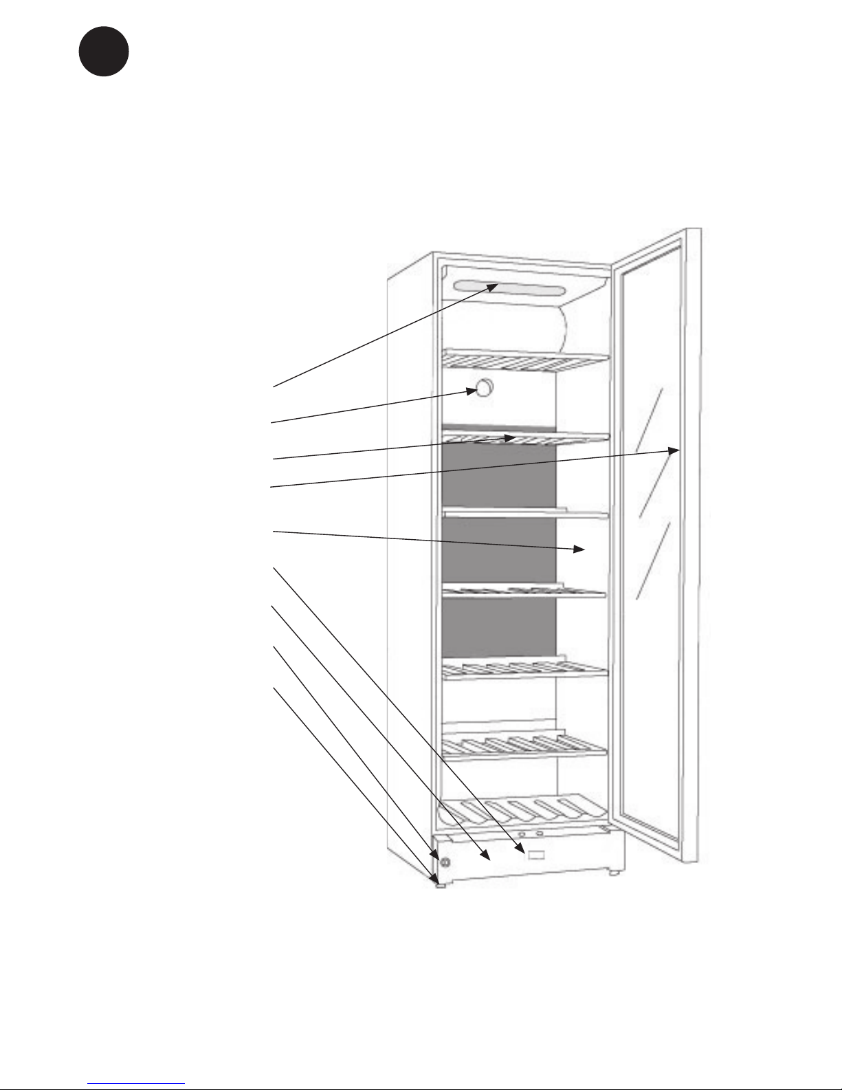
Lighting
Charcoal lter
Wooden shelf
Sealing strip
Name plate
Control panel
Kick plate
Lock
Adjustable feet
Get to know your wine cooler
g.1
Page 7
7
GB
Placement
For safety and operational reasons, the appliance must not be installed outdoors.
The appliance should be placed on a level
surface in a dry, well ventilated room (max.
75% relative air humidity). Never place the
appliance clo se to sources of heat such as
cookers or radiators, and avoid placing it in
direct sunlight.
Ambient temperature
The climate class is stated on the name
plate. This species the optimum ambient
temperature. Wine coolers with winter position, however, function at ambient temperatures as low as 5ºC.
Room temperature
The climate class is stated on the nameplate. This species the optimum room
temperature.
Note that the appliance operates best at
room temperatures from 10°C to 32°C.
Installation and start-up
Wiring and connections in power supply
systems must been all applicable (local and
national) electrical codes. Consult these
codes lengths and sizes prior to cabinet
installation.
This device complies with relevant EU
directives including Low Voltage Directive
2014/35/EU and Electromagnetic Compatibility Directive 2014/30/EU
The socket should be freely accessible.
Connect the appliance only to 220/240 V
/ 50Hz alternating current via a correctly
installed earthed socket.
The socket must be fused with a 10-13 A
fuse.
If the appliance is to be operated in a nonEuropean country, check on the rating plate
whether the indicated voltage and current
type correspond to the values of your mains
supply.
Information regarding voltage, current or
power are given on the rating plate
The power cord may be replaced by a technician only.
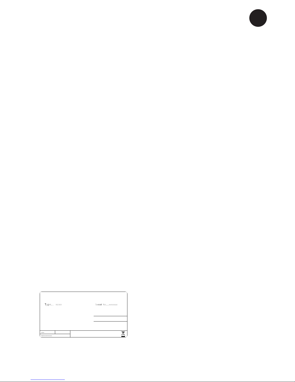
The rating plate provides various technical information as well as type and serial
number.
Electrical connection
g.2
Page 8
8
GB
The surface on which the appliance is to be
placed must be level. Do not use a frame or
similar.
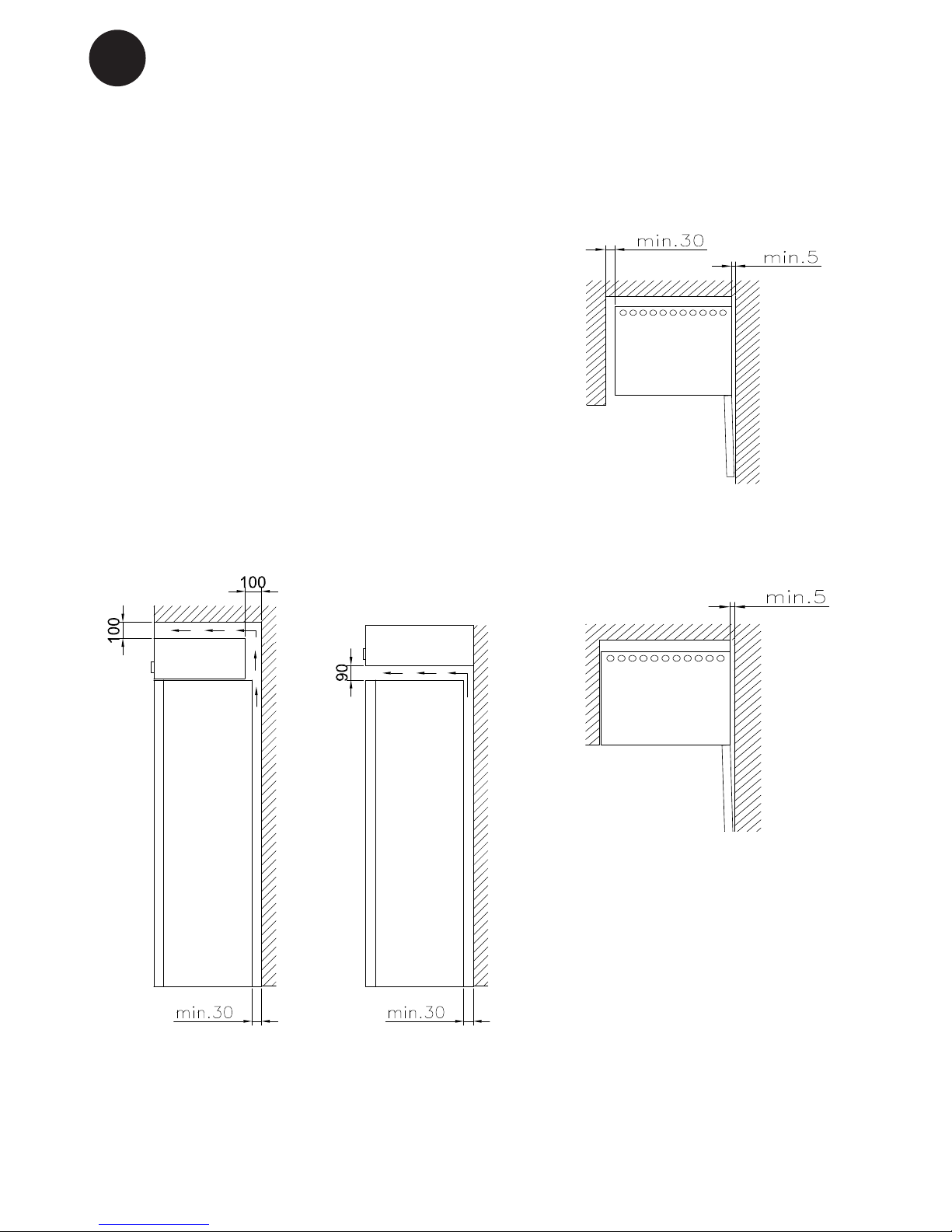
The appliance can be installed as a freestanding unit against a wall, built into a
closet or lined up with other appliances.
It is important that the appliance be well
ventilated and that air can circulate unhindered above, below and around it.
The gures below illustrate how the necessary air circulation around the appliance
can be ensured (gs 3).
g. 3
g. 5
g. 4
Installation
Page 9
9
GB
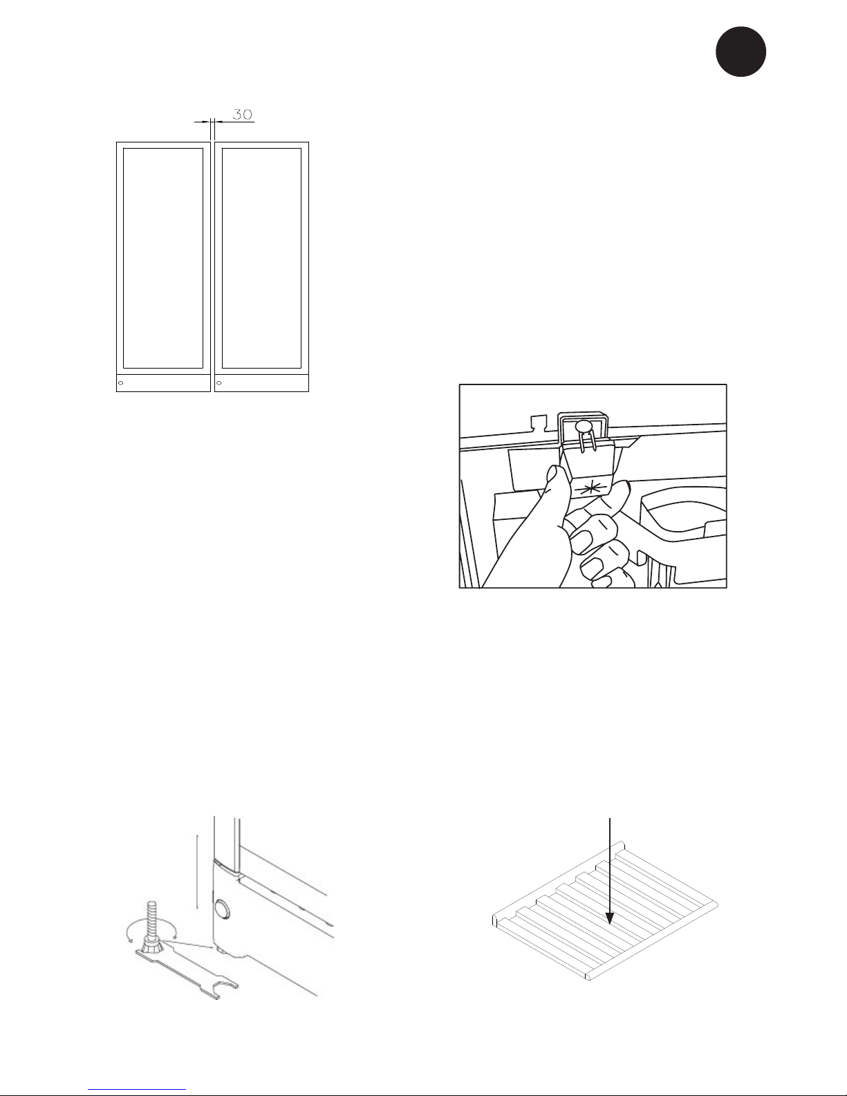
The distance pieces on the rear of the appliance ensure sucient air circulation. Fit
the two caps supplied with the appliance as
shown in g. 7.
g. 7
g. 8
It is important that the appliance be absolutely level. It can be levelled by screwing
the adjustable feet at the front of the appliance up or down (g 8).
Use a spirit level to check that the appliance
is absolutely level sideways.
Setting up
Max. 85 kg.
g. 6
(g 6) A “Side by Side” kit can be ordered
Page 10
10
GB
Reversible door
Follow the instructions carefully
NOTE: Before you start the unit needs to be disconnected from the main grid.
We recommend that the change of door is done by a technician (we recommend two persons)
Helping material:
4 mm Allen key;
Flat-headed screwdriver
Torx 20 (TX20) screwdriver
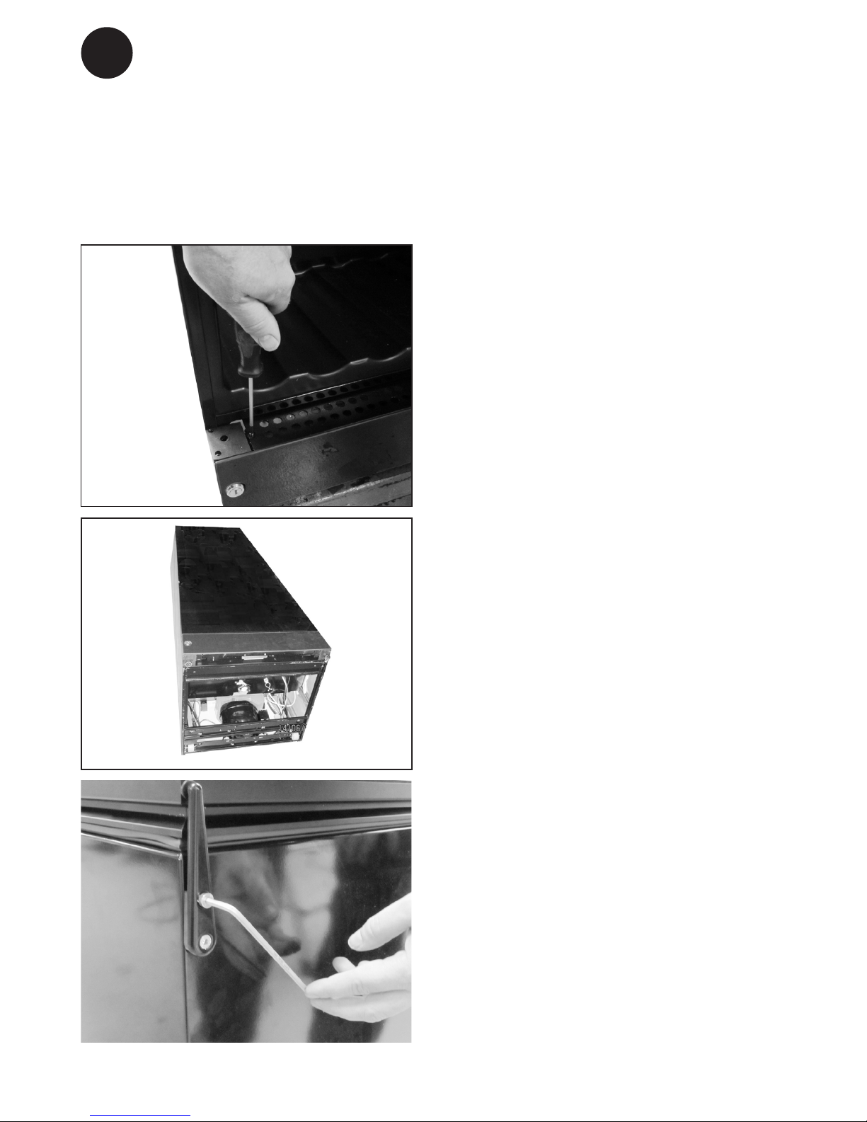
2. Place the appliance on its back (preferably on a soft foundation)
1. Open the door, unscrew the two screws
xing the bottom cover (Torx20). Do not
remove the cover yet.
3. Loosen the upper hinge and remove it ( 4
mm Allen key)
Page 11
11
GB
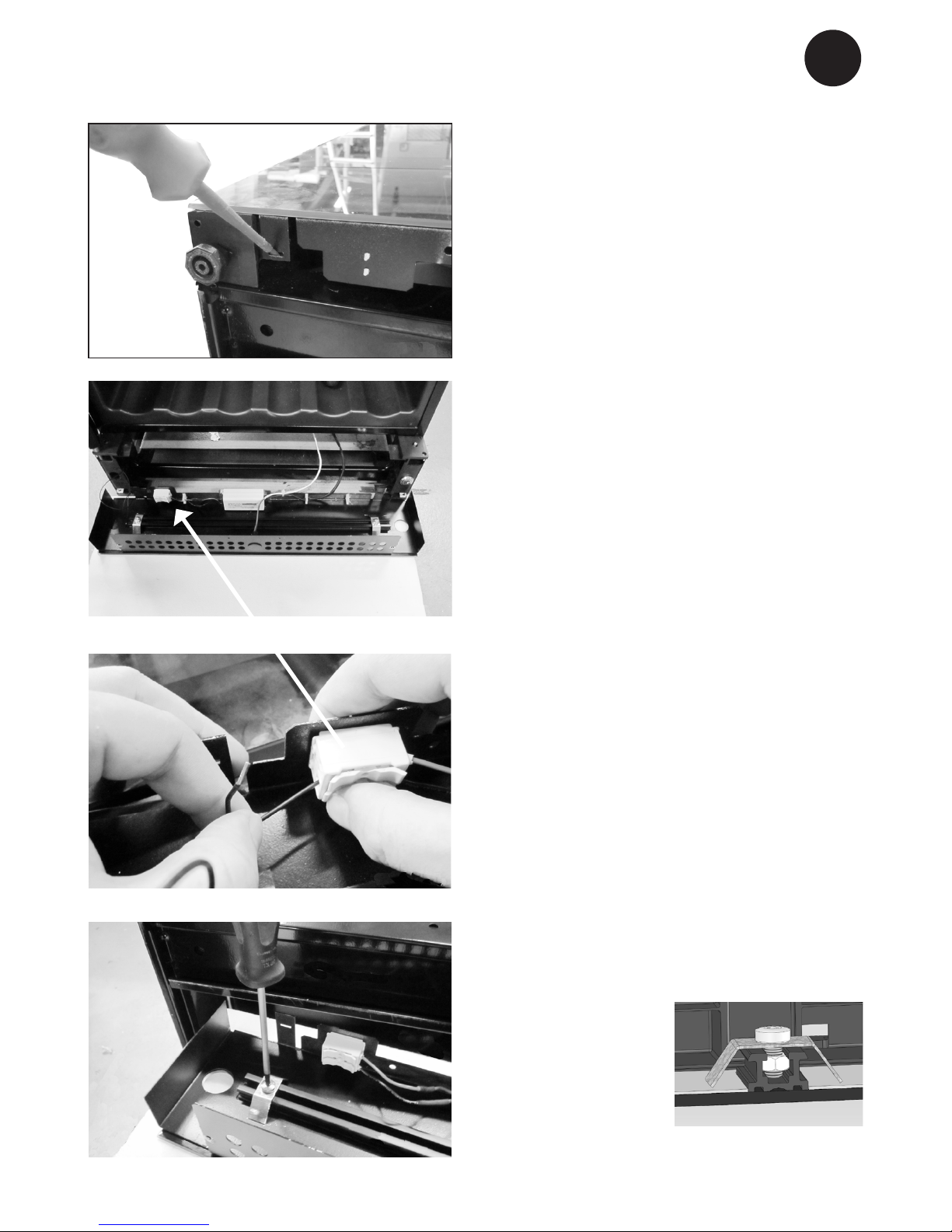
4. Dismount the bottom cover (the buildin snap function in each side can be
unsnapped with the at-headed screwdriver).
5. Place the bottom cover with glass front
down, on an additional support, so the
wires are not stretched.
6. The door LED wires have to be dismounted from the connector on the
bottom cover (pure black & black / white
stripe wires). Push the top release down
to free the wire ends. (Note: the pure
black wire is + and corresponds to the
red wire on opposite side. The black /
white stripe wire is 0 (neutral) and corresponds to the black wire on the opposite
side – this is important when the wires
are to be mounted later)
7. To reverse the bottom glass, the brackets
need to be removed. Loosen the screw
and the bracket incl. screw and bolt
slides of the plastic prole.
NOTE: Now the glass is loose.
Page 12

12
GB
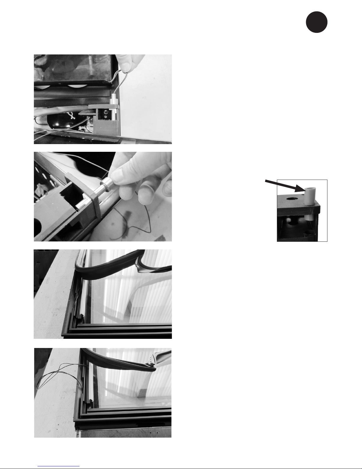
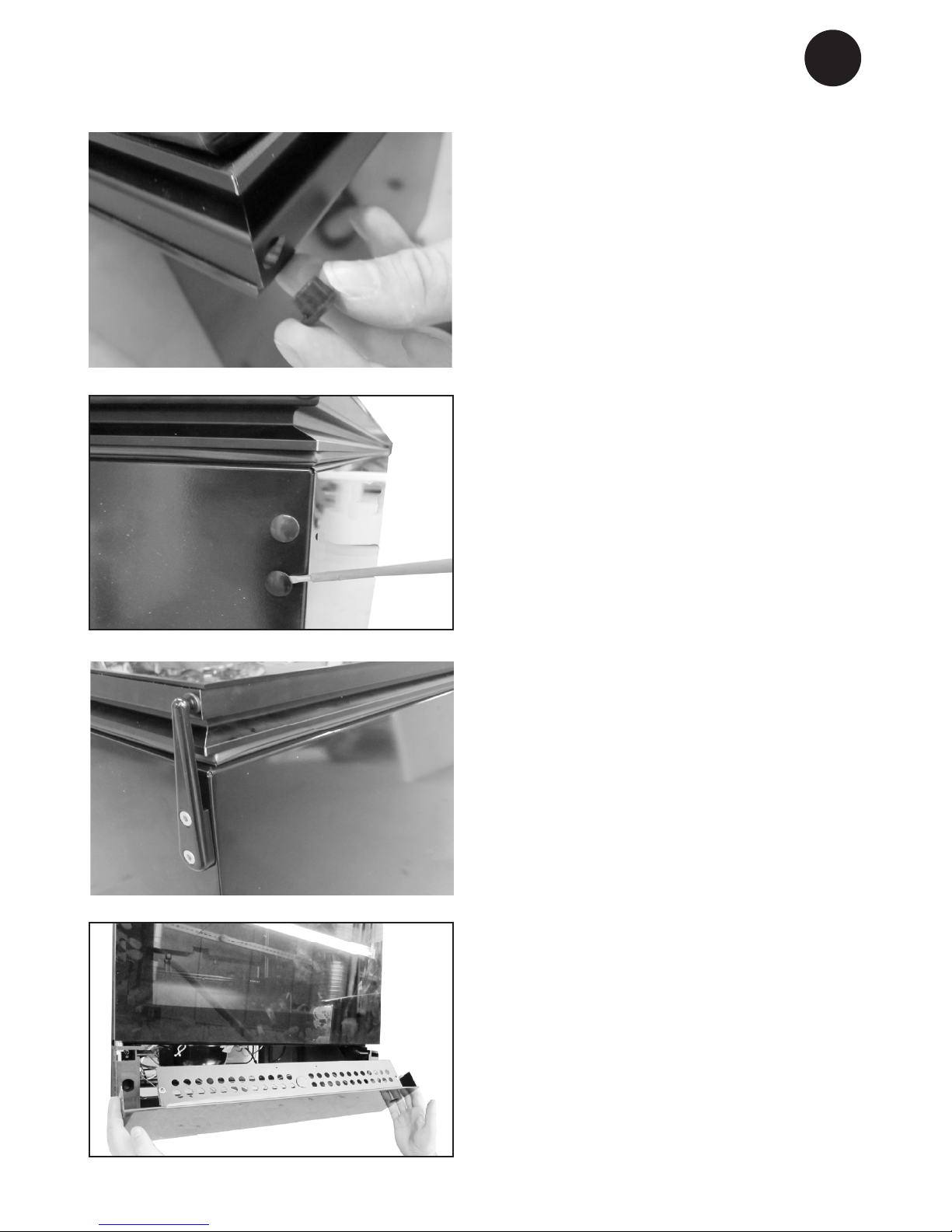
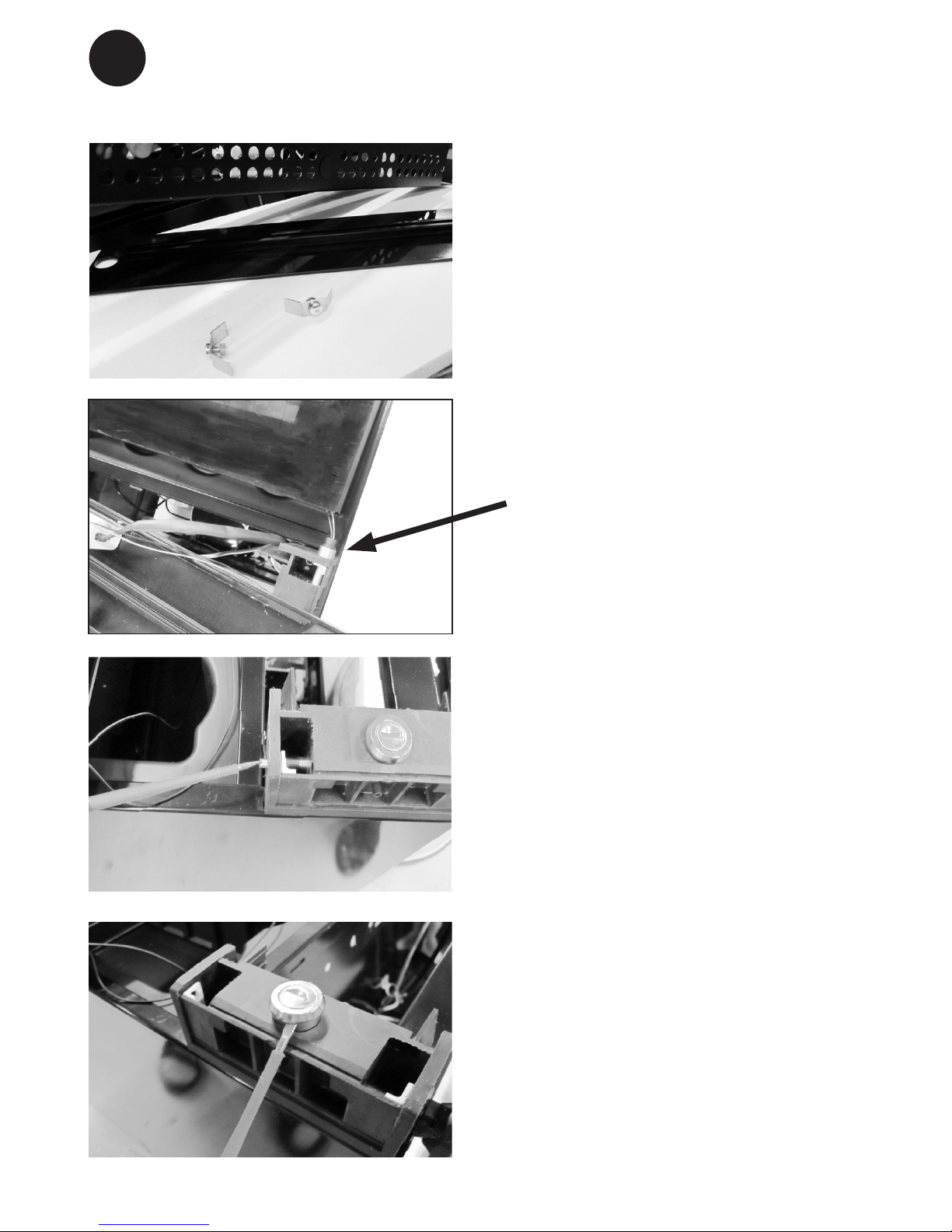
10.Unscrew the lock pin (using the at-headed screwdriver) and remove it.
8. Lift the bottom sheet metal part and turn
the glass so the lock hole ts the other
ends round Ø hole concentric. Place the
sheet metal part on the glass again, and
mount the brackets onto the plastic prole in each end again. Don’t over tighten
the screws.
Note: The nut has to t into the centre
groove.
11.Pull up the lock cylinder and ret both
lock cylinder and lock pin in opposite
side.
9. The door has to be moved up from the
hinge.
Page 13
13
GB
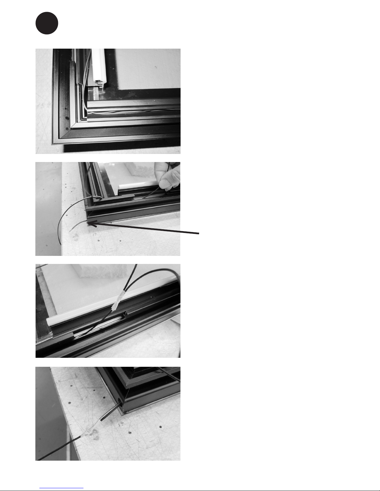
13.Dismount the bottom hinge pin and t it
on the opposite side.
Note: The bush must also be moved.
12. Pull the LED wires gently out of the bot-
tom hinge pin.
14.Turn the door, so the glass side is down
(Note: Place something between the
glass and the other surface (cabinet) so
scratch are minimized).
Then loosen the gasket on the low end of
the door by pulling.
15. Pull the LED wires up and out.
Page 14
14
GB
16.Replace the wires into the plastic groove
and lead them to the other side.
17.Push the wires through the oblong hole
and through the new hinge hole.This can
be a bit tricky so try to mount only one
wire rst
18.Then tape the second wire end to the
rst wire and pull them both fully through
(remove tape subsequently).
Page 15
15
GB
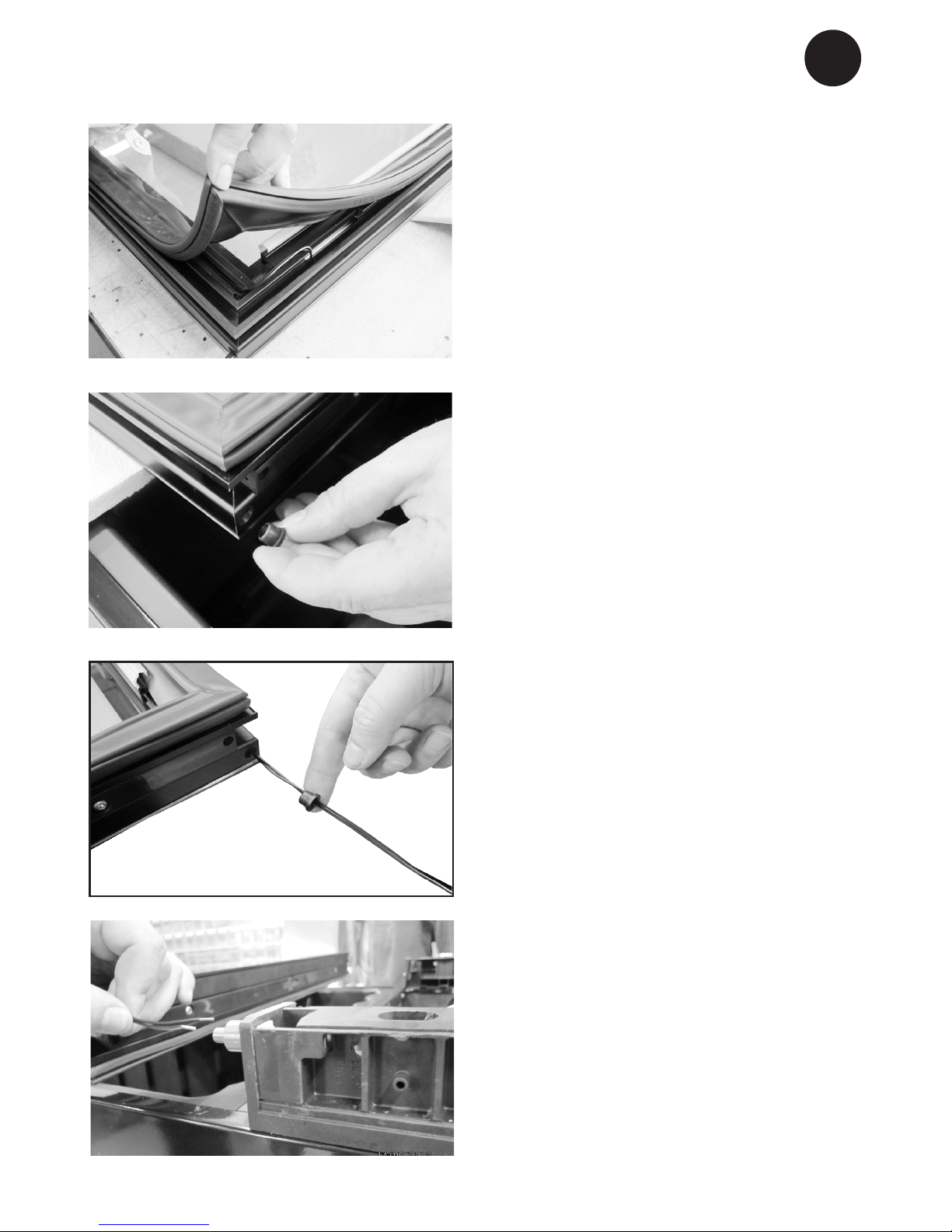
19.Make sure the wires are tted into the
plastic groove and mount the gasket. It’s
important to check that the sealing strip
provides a tight seal all the way round.
If it does not, carefully heat the strip all
the way round using a hair dryer. Then
ease the strip slightly outwards so that it
forms a tight seal against the cabinet. Be
careful not to heat the strip so much that
it melts!
21.Pull the wire through the bushing before
mounting it into the door hinge hole.
20.Dismount the door hinge bushing and
mount it on opposide side.
22.Reverse the door again and displace it
a little on the cabinet proportion to the
botton hinge.
Page 16
16
GB
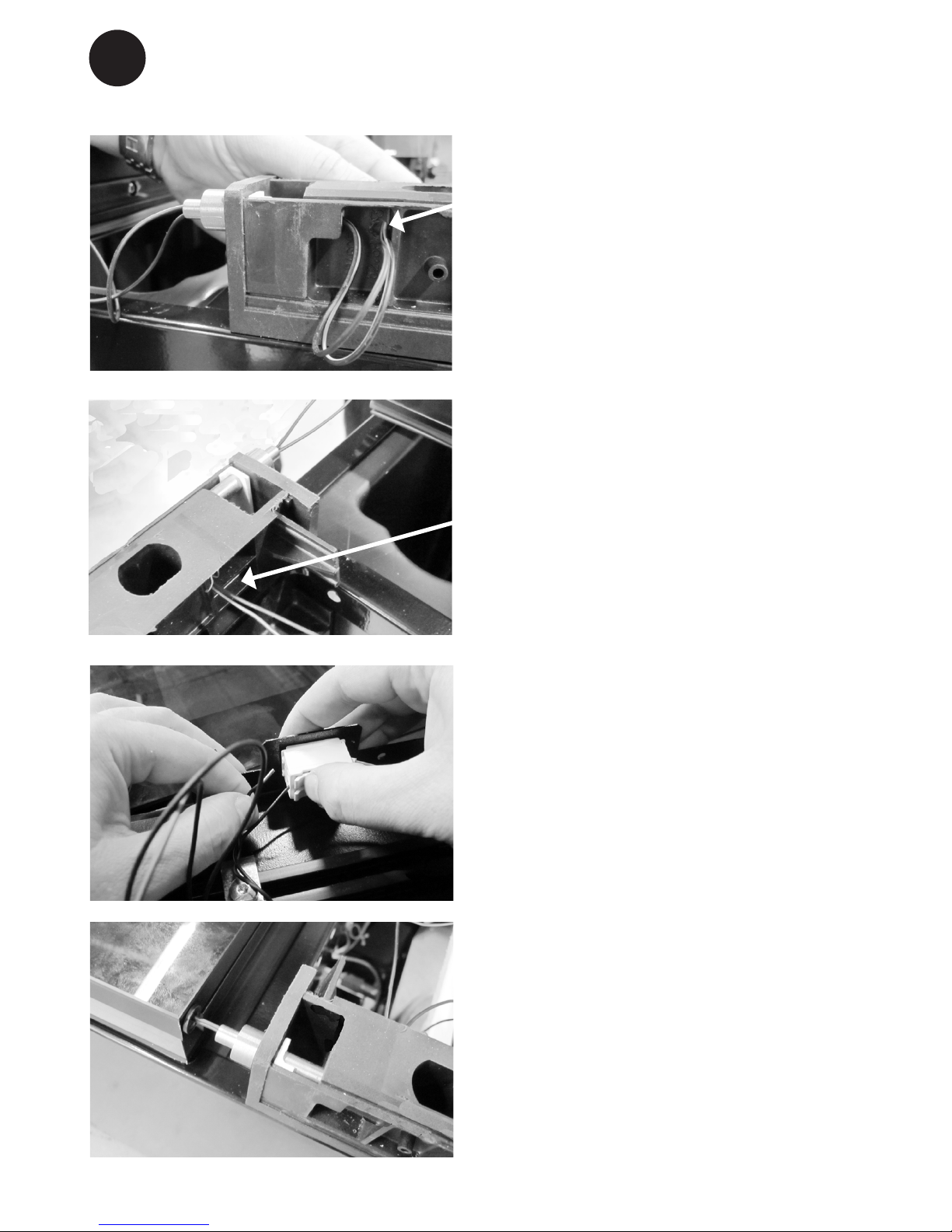
23.Pull the two wires through the bottom
hinge pin....
24.… and through the wire hole in the plastic column.
25.Remount the wires (se under # 6) and
make sure that they are rmly secured.
26.Pusch the door back in place over the
hinge pin and pull the wires simultaneously so the wire do not get stuck.
Page 17
17
GB
27.Dismount the top door bushing and
mount it on opposite side.
28.Dismount the plastic caps on the top of
the cabinet and mount them on opposite
side.
29.Make sure that the door is aligned with
the cabinet before mounting the top
hinge.
30. Remount the bottom front cover. Place
the unit vertically again and mount the
tow screws (see under # 1).
Note: Important: Wait approx. ½ hour
before connecting the unit to the main
grid.
Note: If the door LEDs don’t give out light
but the top LED in the cabinet is shining, it’s most likely that the wires are not
mounted correctly into the connector.
(See under # 6 & 25)
Page 18
18
GB
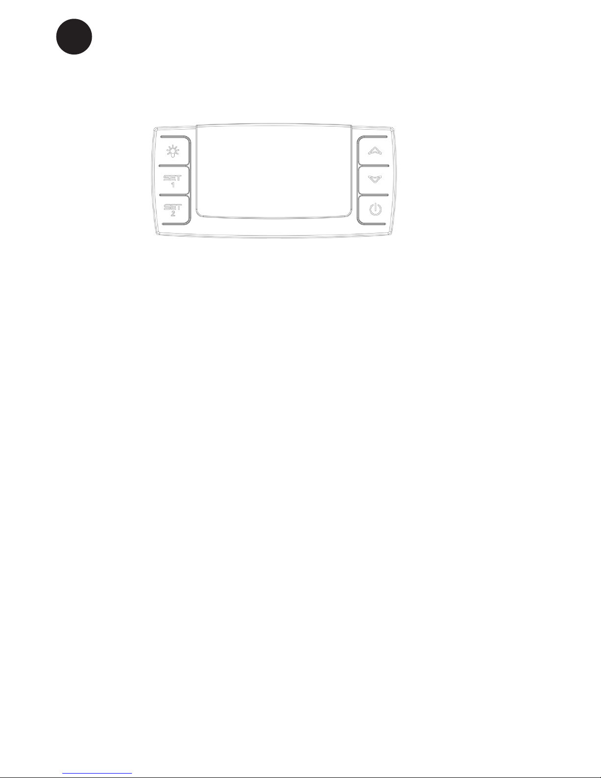
Operation and function
g. 8
Electronic control
The electronic control ensures that the
temperatures set at the top and at the bottom of the appliance are maintained. This is
achieved by means of an advanced control
of the refrigeration system, the heating element, and the fan. The set temperature will
be stored in the event of power failure.
The electronic control has the following
functions:
● On/o switch
● Light switch*
● Temperature setting
● Temperature indication
● Alarm for too high and too low tempera-
tures
● Door alarm
* The light may either be turned on
constantly or only when the door is open.
Temperature indication
The display shows the actual temperature.
The upper digits of the display indicate the
temperature at the top of the appliance, and
the lower digits of the display indicate the
temperature at the bottom of the appliance.
The temperature indicator is equipped with
a built-in lter which simulates the actual
temperature in the bottles. Consequently,
the indicator does not react on short-term
uctuations of the air temperature
Temperature setting
The thermostat is equipped with a child lock
device. This device is activated by pushing
the “up and down” buttons simultaneously.
After approx. 3 seconds “Pof” ashes in the
display. Then the actual temperatures are
shown as usual. In addition, the set temperatures can be shown by pushing SET1
and SET2, respectively.
The child lock device is cancelled by pushing the “up and down” buttons simultaneously. After approx. 3 seconds “Pon” ashes
in the display, and the temperature can be
set.
Temperature setting at the top
of the appliance
Push SET1. Then the temperature at the
top of the appliance can be adjusted up and
down by means of the “up and down” buttons. The temperature can be adjusted from
8 to 22°C, however so that the temperature
cannot be set at a lower temperature than
the actual set point for the bottom temperature sensor.
Page 19
19
GB
Two-zone setting for serving
temperature
Typical serving temperature settings for the
top and bottom sections are 16°C and 6°C
respectively. With these settings, a suitable
temperature gradient will be achieved in
the cabinet for the storage of various types
of wine distributed from top to bottom as
follows:
● heavy red wines +16 to +19°C
● rosé and light red wines +12 to +16°C
● white wines +10 to +12°C
● champagne and sparkling wines +6 to
+8°C
It is recommended that wine be served at a
temperature which is a couple of degrees
lower than the desired drinking temperature
as the wine will be warmed slightly when it
is poured into the glass.
Single-zone setting for longterm storage
For long-term wine storage, the top and bottom sections should both be set at 12°C.
With identical settings for the top and bottom sections, the controls will maintain an
even temperature throughout the cabinet.
However, the temperature in the room will
gradually aect the temperature in the
cabinet through its door and sides, creating
a slight temperature gradient from top to
Temperature setting at the bottom of the appliance
Push SET2. Then the temperature at the
bottom of the appliance can be adjusted up
and down by means of the “up and down”
buttons. The temperature can be adjusted
from 5 to 22°C, however so that the temperature cannot be set at a higher temperature than the actual set point for the upper
temperature sensor.
Alarm devices
There is a sub-alarm for the low-temperature sensor and an excess-alarm for the
high-temperature sensor.
The alarm consists of a beeper and a warning on the display.
Alarm for high temperature: beep sound
+ alternating display of “HtA” and actual
temperature
Alarm for low temperature: beep sound
+ alternating display of “LtA” and actual
temperature
The alarm temperature depends on the set
points.
The beep sound can be cancelled by pushing a random thermostat button. Push the
on/o button to erase the display alarm,
rst for cancelling the alarm, then again for
restarting the compressor.
Door alarm
When the door has been open for more
than 2 minutes the door alarm is activated.
Light
To turn o the lights, press once
Permanent lighting
For presentation purposes of your wine,
you can turn the lights permanently. Please
press the light switch image twice. To
switch o the lights press on again.
Page 20

20
GB
Automatic defrosting.
The wine cooler is defrosted automatically.
Defrost water runs through a pipe and is
collected in a tray above the compressor
where the heat generated by the compressor causes it to evaporate. The defrost
water tray should be cleaned at intervals.
Cleaning.
Before cleaning the appliance, unplug it
from the main supply. The cabinet is best
cleaned using warm water (max. 65°C) with
a little mild detergent. Never use cleaning
agents that scour. Use a soft cloth. Rinse
with clean water and dry thoroughly. The
defrost water channel, in which condensation from the evaporator runs, is located
at the bottom of the rear inside wall of the
cabinet and must be kept clean. Add a few
drops of disinfectant, e.g. Rodalon, to the
defrost water drain a couple of times a year,
and clean the drain using a pipe cleaner or
similar. Never use sharp or pointed implements.
The sealing strip around the door must be
cleaned regularly to prevent discolouration
and prolong service life. Use clean water.
After cleaning the sealing strip, check that it
continues to provide a tight seal.
Dust collecting on the condenser on the
rear of the cabinet, the compressor and
in the compressor compartment is best
removed using a vacuum cleaner.
Defrosting, cleaning
and maintenance.
bottom. The controls will maintain the set
temperature at the bottom of the cabinet,
and any deviation from the setting will
therefore occur at the top.
The dierence will vary from 0 to 3°C, depending on the ambient temperature.
Page 21
21
GB
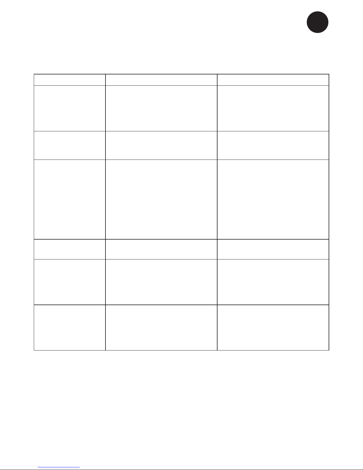
Fault nding
Fault Possible cause Remedy
The appliance is not
working.
The appliance is switched o.
Power failure; the fuse is blown;
the appliance is not plugged in
correctly.
Press the on/o switch.
Check that power is connected.
Reset the fuse.
Water collects in
the bottom of the
cabinet.
The defrost water pipe is
blocked.
Clean the defrost water channel
and the drain hole on the rear
wall of the cabinet.
Vibration or
bothersome noise.
The appliance is not level.
The appliance is resting against
other kitchen elements.
Containers or bottles inside the
cabinet are rattling against one
another.
Level the appliance using a spirit
level.
Move the appliance away from
the kitchen elements or appliances it is in contact with.
Move containers and/or bottles
apart.
Compressor runs
continuously.
High room temperature. Ensure adequate ventilation.
P1 is shown on the
display.
The upper sensor is disconnected or short-circuited.
Call for service. The temperature
within the entire cabinet is maintained at the higher of the two
setpoints until the fault has been
corrected.
P2 is shown on the
display.
The lower sensor is disconnected
or short-circuited.
Call for service. The temperature
within the entire cabinet is maintained at the higher of the two
setpoints until the fault has been
corrected.
Page 22

22
GB
Warranty, spare parts and service.
Warranty disclaimer
Faults and damage caused directly or
indirectly by incorrect operation, misuse,
insucient maintenance, incorrect building,
installation or mains connection. Fire, accident, lightening, voltage variation or other
electrical interference, including defective
fuses or faults in mains installations.
Repairs performed by others than approved
service centres and any other faults and
damage that the manufacturer can substantiate are caused by reasons other than
manufacturing or material faults are not
covered by the warranty.
Please note that changes to the construction of the appliance or changes to the
component equipment of the appliance will
invalidate warranty and product liability, and
the appliance cannot be used lawfully. The
approval stated on rating plate will also be
invalidated.
Transport damage discovered by the buyer
is primarily a matter to be settled between
the buyer and the distributor, i.e. the distributor must ensure that such complaints
are resolved to the buyer’s satisfaction.
Before calling for technical assistance,
please check whether you are able to
rectify the fault yourself. If your request for
assistance is unwarranted, e.g. if the appliance has failed as a result of a blown fuse
or incorrect operation, you will be charged
the costs incurred by your call for technical
assistance.
Spare parts
When ordering spare parts, please state
the type, serial and product numbers of
your appliance. This information is given on
the rating plate. The rating plate contains
various technical information, including type
and serial numbers.
Product numbers
Page 23

23
GB
Disposal
Information for Users on Collection
and Disposal of Old Equipment and
used Batteries
These symbols on the products,
packaging, and/or accompanying
documents mean that used electrical and electronic products and
batteries should not be mixed with
general household waste. For proper
treatment, recovery and recycling
of old products and used batteries,
please take them to applicable collection points, in accordance with your
national legislation and the Directives
2002/96/EC and 2006/66/EC.
By disposing of these products and
batteries correctly, you will help to
save valuable resources and prevent
any potential negative eects on
human health and the environment
which could otherwise arise from
inappropriate waste handling.
For more information about collection and recycling of old products and
batteries, please contact your local
municipality, your waste disposal
service or the point of sale where you
purchased the items.
Penalties may be applicable for incorrect disposal of this waste, in accordance with national legislation.
For business users in the European Union.
If you wish to discard electrical and
electronic equipment, please contact
your dealer or supplier for further
information.
[Information on Disposal in other
Countries outside the European
Union]
These symbols are only valid in the
European Union. If you wish to discard this product, please contact your
local authorities or dealer and ask for
the correct method of disposal.
Note for the battery symbol:
This symbol might be used in combination with a chemical symbol. In this
case it complies with the requirement
set by the Directive for the chemical
involved.
Page 24

2
DE
Warnung
WARNUNG:
Verwenden Sie keine anderen
mechanischen Geräte oder Hilfsmittel, um den Abtauprozess zu
beschleunigen, als diejenigen,
die vom Hersteller empfohlen
sind.
WARNUNG:
Beschädigen Sie nicht den Kühlkreislauf.
WARNUNG:
Verwenden Sie keine elektrischen Geräte im Gerät, es sei
denn, dass die Geräte vom Hersteller empfohlen sind.
WARNUNG:
Das Gerät nicht dem Regen
aussetzen.
WARNUNG:
Dieses Gerät ist nicht zur Verwendung durch Personen
(einschließlich Kinder) mit eingeschränkten physischen, sensorischen oder geistigen Fähigkeiten oder fehlender Erfahrung
und Wissen bestimmt, es sei
denn, eine angemessene Aufsicht oder Anleitung zur Benut-
Da ein brennbares Gas als Kältemittel in diesem Gerät dient, ist
es wichtig sicherzustellen, dass
kein Teil des Kühlkreislaufs oder
der Rohre beschädigt ist.
Die Menge und Art von Kältemittel im Gerät ist auf dem
Typenschild angegeben.
Der Standard EN378 speziziert,
dass der Raum, in dem das Gerät installiert wird, ein Volumen
von 1m³ pro 8 g Kohlenwassersto-Kältemittel, das im Gerät
verwendet ist, haben soll. Dies
ist zu beachten, um die Bildung
von leicht entzündlichen Gasgemischen in dem Raum, wo das
Gerät installiert ist, zu vermeiden, falls eine Undichtigkeit des
Kuhlkreislaufs entsteht.
WARNUNG:
Bitte beachten Sie bei der Platzierung der Waren im Gerät,
dass die Luftzirkulation durch
Verstellen der Luftaus- trittsönungen des Lüfters nicht behindert wird.
Page 25

3
DE
zung des Geräts durch eine für
ihre Sicherheit zuständige Person ist gegeben. Kinder sollten
beaufsichtigt werden um sicherzustellen, dass sie nicht mit dem
Gerät spielen
WARNUNG:
Keine Produkte mit brennbaren
Treibgasen (z. B. Spraydosen)
und keine explosiven Stoe lagern. Explosionsgefahr
WARNUNG:
Gefahr von Feuer oder Explosion wenn brennbares Kältemittel ist verwendet. Darf nur von
Fachpersonal repariert werden
● Vor Reparatur oder Reinigung
des Gerätes den Netzstecker
aus der Steckdose ziehen.
● Wenn die Anschlussleitung
beschädigt ist, darf sie nur von
einem autorisierten Kundendienst ausgewechselt werden,
um Gefahr zu vermeiden.
● Beachten Sie bitte, dass Ände-
rungen der Konstruktion dieses
Gerätes zur Folge haben, dass
Gewährleistung und Produkthaftung erlöschen.
● Dieses Gerät eignet sich ins-
besondere zur Lagerung von
Getränken in Flaschen oder
Dosen.
● Before servicing or cleaning
the appliance, unplug the
appliance from the mains or
disconnect the electrical power
supply
● ldung von Reif auf der inne-
ren Verdampferplatte und den
obersten Teilen ist normal. In
Verbindung mit Reinigung oder
Wartung muss das Gerät deshalb entfrostet werden.
● Dieses Gerät ist ausschließlich
zur Lagerung von Wein bestimmt
● Nur im Innenbereich anwen-
den
Beleuchtung: Klasse 1, LED Produkt
Page 26

4
DE
Warnung .................................................2
Vor dem Gebrauch. ................................5
Lernen Sie .............................................6
Elektrischer Anschluss. ..........................7
Inbetriebnahme und Installation .............7
Wendbare Tür .........................................9
Bedienung und Funktion.......................18
Abtauen, Reinigung und Wartung
Fehlersuche .......................................... 20
Fehlersuche .......................................... 21
Ersatzteile und Service ......................... 22
Entsorgung ...........................................23
Inhalt
Der Energieverbrauch ist geringer…
1) ..je niedriger die Umgebungstemperatur
ist
2) ..je wärmer der Thermostatsollwert eingestellt ist
3) ..je weniger man die Tür önet und umso
kürzer die Türönungszeit ist.
Energieeinsparung während des Gebrauchs
Page 27

5
DE
Kontrollieren Sie das Gerät sofort bei
Lieferung auf eventuelle Beschädigungen.
Transportschäden sind dem Händler zu
melden, bevor das Gerät in Gebrauch
genommen wird.
Verpackung entfernen. Das Schrankinnere
mit lauwarmem Wasser und etwas mildem
Spülmittel reinigen. Mit klarem Wasser
nachwischen und gründlich trocknen (siehe
“Reinigung”). Verwenden Sie ein weiches
Tuch.
Falls das Gerät liegend transportiert wurde
oder einer Temperatur von weniger als +5
°C ausgesetzt war, muss es vor dem Einschalten mindestens eine Stunde lang bei
höherer Außentemperatur aufrecht stehen.
Vor dem Gebrauch
Page 28

6
DE
Abb.1
Beleuchtung
Kohlelter
Holzfach
Dichtleiste
Typenschild
Sockelblende
Bedienungselemente
Schloss
Einstellbare Füße
Lernen Sie Ihren Weinschrank zu kennen
Page 29

7
DE
Aufstellort.
Aus Sicherheits- und betriebstechnischen
Gründen darf das Gerät nicht im Freien
aufgestellt werden.
Stellen Sie den Schrank auf einen ebenen
Untergrund in einem trockenen, gut belüfteten Raum (max. 75 % relative Luftfeuchtigkeit). Stellen Sie den Schrank nicht in
unmittelbarer Nähe von Wärmequellen wie
Herden oder Heizkörpern auf, und vermeiden Sie direkte Sonneneinstrahlung oder
Wärme von anderen Wärmequellen .
Umgebungstemperatur
Die Klimaklasse nden Sie auf dem Typenschild. Sie gibt an, innerhalb welcher Umgebungstemperatur bereiche der Kühlschrank
optimal arbeitet. Weinschränke mit Winterposition fungieren bis zu einer Umgebungstemperatur von 5 °C.
Beachte: Das Gerät arbeitet am besten bei
Raumtemperaturen von 10 ° bis 32 ° C
Inbetriebnahme und
Installation
Elektrischer Anschluss
Verkabelung und Anschlüsse in Stromversorgungssystemen müssen allen (örtlichen
und nationalen) Elektrovorschriften entsprechen. Machen Sie sich vor dem Einbau mit
den Angaben in diesen Vorschriften vertraut
Dieses Gerät entspricht den einschlägigen
EU-Richtlinien einschließlich:
Niederspannungsrichtinie 2014/35/EU.
Elektromagnetische Kompatibilitätsrichtlinie
2014/30/EU
Die Steckdose sollte frei zugänglich sein.
Das Gerät an (220/240 V / 50Hz) Wechselstrom über eine vorschriftsmäßig installierte
Steckdose anschließen.
Die Steckdose muss mit einer 10A - 13A
Sicherung abgesichert sein.
Bei Geräten, die in nicht-europäischen Ländern betrieben werden, ist auf dem Typenschild zu überprüfen, ob die angegebene
Spannung und Stromart mit den Werten
Ihres Stromnetzes übereinstimmt.
Informationen über Spannung und Leistungsaufnahme / Strom sind auf dem
Typenschild.
Das Typenschild, das sich im Gerät bendet, enthält verschiedene technische
Angaben sowie Typen- und Seriennummer.
Ein eventuell notwendiger Austausch der
Netzanschlussleitung darf nur durch einen
Fachmann erfolgen
Abb..2
Page 30

8
DE
Installation
Die Unterlage zum Aufstellen des Schranks
muss eben sein. Verwenden Sie keinen
Rahmen o.ä.
Der Schrank kann frei an einer Wand
stehen, in ein Schrank eingebaut werden
oder neben anderen Schränken aufgestellt
werden
Der Schrank muss ausreichend belüftet
sein, und die Luftzirkulation über und unter
ihm sowie seitlich vom Schrank darf nicht
behindert sein.
Wird der Schrank an einer Wand aufgestellt, ist darauf zu achten, soviel Platz zu
lassen, dass die Tür genug geönet werden
kann.
g. 3
g. 5
g. 4
Page 31

9
DE
Der Schrank muss waagerecht stehen. Der
Schrank kann durch Drehen der einstellbaren Füße ausgerichtet werden
(siehe Abb. 7).
Prüfen Sie mit einer Wasserwaage nach, ob
der Schrank waagerecht steht.
Aufstellung
g. 6
g. 7
Max. 85 kg.
Die Abstandsstücke auf der Rückseite des
Schranks sichern die erforderliche Luftzirkulation. Die beiden Abdeckungen montieren,
die zusammen mit dem Schrank mitgeliefert
werden (siehe Abb. 6)
(Zwei verschiedene Modelle)
Belüftung
g. 6
(g.6)
A “Seite an Seite” Kit kann bestellt werden
Page 32

10
DE
Wendbare Tür
Folgen Sie sorgfältig der Anleitung
Hinweis: Bevor Sie starten das Gerät vom Stromnetz trennen.
Wir empfehlen den Wechsel des Türanschlages vom einem Techniker ausführen zu lassen (wir
empfehlen zwei Personen)
Hilfsmaterial:
4 mm Inbusschlüssel
Schlitzschrauben dreher
Torx 20 (TX20) Schraubendreher
2. Legen Sie das Gerät auf die Rückseite
(am besten auf einer weichen Unterlage)
1.Tür önen und die beiden Schrauben für
die untere Blende entfernen. (Torx 20)
Die Blende jetzt noch nicht entfernen.
3. Lösen und entfernen Sie das obere
Scharnier (4 mm Inbus)
Page 33

11
DE
4. Entfernen Sie die untere Blende
(Die beiden Rastfunktionen an den Sei-
ten können mit einem Schlitzschraubendreher entrastet werden.)
5. Legen Sie die Blende mit der Glasseite
nach unten auf eine Unterlage, damit
das Glas keine Kratzer bekommt und die
Kabel nicht gespannt sind.
6. Lösen Sie das Kabel zum LED-Türlicht
am Verbinder (schwarzes und schwarz/
weißes Kabel, drücken Sie auf die jeweilige Wippe).
(Hinweis: das schwarze Kabel ist +12V
und ist verbunden mit dem roten Kabel
vom Trafo auf der gegenüberliegenden
Seite. Das schwarz/ weiße Kabel vom
LED-Licht ist verbunden mit dem schwarzen Kabel vom Trafo. – wichtig wenn die
Kabel später wieder verbunden werden
müssen.)
7. Um die Glasscheibe zu drehen müssen
beide Halterungen am Plastikprol gelöst
werden und können dann zur Seite entfernt werden.
Hinweis: Nun ist die Scheibe lose
Page 34

12
DE
10.Sicherungsstift mit dem Flachschrau
bendreher entfernen.
8. Heben Sie die Blende und drehen die
Glasscheibe, das Loch für das Schloss
muss konzentrisch zum Loch in der
Blende liegen. Montieren Sie die beiden
Halterungen am Plastikprol.
Nicht die Schrauben überdrehen.
11.Ziehen Sie den Schließzylinder heraus
und montieren Sie Zylinder und Stift auf
der gegenüberliegenden Seite.
9. Die Tür aus dem Gelenk heben.
Page 35

13
DE
13. Demontieren Sie den unteren Scharni-
erstift und setzen ihn auf der gegenüberliegenden Seite wieder ein.
Hinweis: Die Buchse muss auch bewegt
werden.
12. Ziehen Sie die LED-Kabel vorsichtig
aus dem Scharnier.
14.Drehen Sie die Tür, das Glas zeigt nun
nach unten.
Hinweis:Legen Sie etwas Weiches zwi-
schen Glas und Gerät um die Gefahr von
Kratzern zu vermeiden.
Ziehen Sie die Türdichtung am unteren
Ende ab.
15. Ziehen Sie die LED-Kabel herausziehen.
Page 36

14
DE
16.Die beiden Kabel werden nun im Plastikkanal zur anderen Seite geführt.
17.Die Kabel müssen nun in das Langloch
eingeführt werden und kommen aus dem
neuen Scharnierloch wieder heraus.
Dies ist ein wenig kompliziert. Versuchen
Sie es deshalb zuerst nur mit einem
Kabel.
18.Mit Klebeband befestigen Sie das zweite
Kabel am ersten und ziehen dann beide
ganz hindurch. (Klebeband wieder entfernen)
Page 37

15
DE
19.Vergewissern Sie sich, dass die Kabel
richtig im Plastikprol liegen und montieren Sie die Türdichtung wieder.
Überprüfen Sie ob die Türdichtung
rundherum richtig schließt.
Falls nicht erwärmen Sie die Türdichtung
vorsichtig mit einem Haarfön und ziehen
Sie die Dichtung leicht nach außen.
Seien Sie vorsichtig beim Erwärmen,
damit die Dichtung nicht schmilzt.
21.… nach Durchfädelung der Kabel durch
die Buchse einsetzen.
20.Die Türanschlagbuchse demontieren
und auf der gegenüberliegenden Seite
wieder…….
22.Die Tür wird zurückgedreht und ein
wenig oberhalb zum unteren Scharnier
plaziert.
Page 38

16
DE
23.Die beiden Kabel werden durch den
Scharnierstift ……
24.… und durch das Loch der Plastiksäule
gezogen.
25.Die beiden Kabel werden wieder montiert (siehe unter # 6)
26.Die Tür wird nun auf den Scharnierstift geschoben, gleichzeitig wird an
den Kabeln gezogen, damit diese nicht
eingeklemmt werden.
Page 39

17
DE
27.Die obere Türbuchse wird demontiert
und auf der gegenüberliegenden Seite
wieder eingesetzt.
28.Die Kunststokappen oben am Gerät
werden an der gegenüberliegenden Seite
montiert
29.Bevor Sie das obere Scharnier wieder montieren richten Sie die Tür zum
Schrank richtig aus,
30. Die untere Blende wird wieder montiert..
Das Gerät wird aufgestellt und die beiden
Schrauben in der Blende montiert
(siehe unter # 1)
Hinweis: Wichtig: Warten Sie ca. eine
halbe Stunde bevor Sie das Gerät wieder
einschalten.
Hinweis: Wenn das Türlicht nicht funk-
tioniert, das Licht im Schrank jedoch,
überprüfen Sie bitte die Verbindungen
(siehe unter # 6 & 25)
Page 40

18
DE
Elektronische Steuerung.
Die elektronische Steuerung sorgt dafür
dass die eingestellten Temperaturen oben
und unten im Gerät gehalten werden. Dies
wird mit der fortschrittlichen Steuerung im
Zusammenspiel von Kühlsystem, Wärmeleitung und Ventilator erreicht.
Nach einem evt. Stromausfall kehrt das
System automatisch zu den eingestellten
Temperaturwerten zurück.
Die elektronische Steuerung
hat folgende Funktionen:
● Ein/Aus Schalter
● Lichtschalter*
● Temperatureinstellung
● Temperaturanzeige
● Automatisches Abtauen
● Alarmanzeige bei zu hoher oder niedriger
Temperatur
● Türalarm
* Das Licht kann entweder generell oder nur
bei geöneter Tür brennen.
Bedienung und Funktion.
Abb. 8
Temperaturanzege.
Das Display zeigt die aktuelle Temperatur.
Die obere Zahl im Display zeigt die Temperatur oben im Gerät, die untere Zahl die
Temperatur unten im Gerät. Die Temperaturanzeige hat ein eingebautes Filter
mit dem die Temperatur in den Flaschen
simuliert wird. Deshalb reagiert die Anzeige
nicht auf kurzzeitige Änderungen der Lufttemperatur z.B nach dem Önen der Tür
Temperatureinstellung.
Der Termostat hat eine Kindersicherung.
Sie wird durch gleichzeitiges drücken der
Tasten „hoch und runter“ von ca. 3 sek. eingeschaltet. Im Display blinkt ”Pof”. Danach
wird wieder die aktuelle Temperatur angezeigt. Ausserdem kann man durch Drücken
von SET1 und SET2 die eingestellten
Temperaturen sehen.
Die Kindersicherung wird durch gleichzeitiges Drücken von „hoch und runter“ von ca.
3 sek. wieder ausgeschaltet und im Display
blinkt „Pon“. Danach können Temperaturen
eingestellt werden.
Page 41
19
DE
Mehrzoneneinstellung für
Serviertemperierung.
Typisch für diese Anwendung ist eine
Oberteil-/Boden-Einstellung von 16/6 °C.
Mit dieser Einstellung verteilen sich die
Temperaturen durch den Schrank zur
Aufbewahrung verschiedener Weintypen
gemäß folgender von oben nach unten
gehender Reihenfolge:
● schwere Rotweine +16 bis +19 °C
● Rosé und leichte Rotweine +12 bis
+16°C
● Weißwein +10 bis +12 °C
● Champagner und Schaumweine +6 bis
+8°C
Es empehlt sich, die Weine ein paar
Grade kälter als die gewünschte Trinktemperatur zu servieren, da sich der Wein
beim Einschenken ins Glas rasch etwas
erwärmt.
Einzoneneinstellung für
Langzeitlagerung.
Zur Langzeitlagerung von Weinen empehlt sich eine Oberteil-/Boden-Einstellung
von 12/12 °C.
Mit der gleichen Einstellung im Oberteil
und Boden sorgt das Kühlsystem für
Temperatureinstellung oben.
Drücke auf SET1. Danach kann die Temperatur oben im Gerät mit den Tasten „rauf
und runter“ gewählt werden. Der Einstellbereich geht von 8 bis 22*C, jedoch kann
kein Wert kleiner als der Temperaturwert für
unten gewählt werden.
Temperatureinstellung unten.
Drücke auf SET2. Danach kann die Temperatur unten im Gerät mit den Tasten „rauf
und runter“ gewählt werden. Der Einstellbereich geht von 5 bis 22*C, jedoch kann kein
Wert höher als der Temperaturwert für oben
gewählt werden.
Alarmfunktion.
Der Alarm wird durch einen Piepton und
eine Anzeige im Display signalisiert.
Alarm bei zu hoher Temperatur: Piepton
und die Anzeige blinkt zwischen „HtA“ und
aktueller Temperatur.
Alarm bei zu tiefer Temperatur: Piepton
und die Anzeige blinkt zwischen „LtA“ und
aktueller Temperatur.
Die Alarmtemperaturen sind abhängig von
den eingestellten Temperaturwerten.
Der Piepton kann durch Drücken einer
beliebigen Taste abgeschaltet werden.
Um die Alarmanzeige abzuschalten muss
die on/o Taste 2mal gedrückt werden,
zuerst um den Alarm zurückzusetzen und
danach noch einmal um das Gerät neu zu
starten.
Türalarm
Wenn die Tür länger als 2 min oen steht
wird der Türalarm aktiviert.
Beleuchtung.
So schalten Sie das Licht, drücken Sie
einmal
Zu Präsentationszwecken ihres Weines
können sie die Beleuchtung auch dauerhaft
einschalten. Dazu Lichtschalter zweimal
drücken. Zum Abschalten der Beleuchtung
Lichtschalter erneut drücken.
Page 42

20
DE
Automatisches Abtauen des
Kühlschranks.
Der Kühlschrank wird automatisch abgetaut, das Tauwasser läuft durch ein
Rohr in die Tauwasserschale, die sich auf
dem Kompressor bendet. Das Wasser
verdampft durch die Betriebswärme des
Kompressors. Die Tauwasserschale ist
gelegentlich zu reinigen.
Reinigung.
Zum Reinigen des Schrankinnern den
Schrank am Ein-/Ausschalter ausschalten. Eine Mischung aus warmem Wasser
und Spülmittel (max. 65 °C) ist dazu am
besten geeignet). Verwenden Sie keine
Reinigungsmittel, die Kratzer verursachen
können. Verwenden Sie ein weiches Tuch.
Mit klarem Wasser nachwischen und gut
abtrocknen. Die Tauwasserrinne, durch die
das Kondenswasser vom Verdampfer herab
läuft, bendet sich innen an der Schrankrückwand. Sie ist stets sauber zu halten.
Tropfen Sie mehrmals jährlich ein Desinfektionsmittel in den Tauwasserabuss. Mit
einem Pfeifenreiniger o.ä. reinigen. Niemals
scharfkantige oder spitze Gegenstände
verwenden.
Die Türdichtleiste muss regelmäßig gereinigt werden, um Verfärbungen zu vermeiden und lange Haltbarkeit zu gewährleisten. Klares Wasser verwenden. Nach der
Reinigung der Türdichtleiste prüfen, ob sie
dicht schließt.
Vom Rückwandverüssiger, Kompressor
und Kompressorraum den Staub am besten
mit einem Staubsauger entfernen.
Abtauen, Reinigung
und Wartung
eine gleichmäßige Temperatur im ganzen
Schrank.
Jedoch drängt die Umgebungstemperatur
langsam durch die Tür und Seiten des
Schranks ein und verursacht einen kleinen
Temperaturunterschied zwischen Oberteil
und Boden. Der Schrank wird am Boden
nach der eingestellten Temperatur gesteuert, weshalb Abweichungen im Oberteil
auftreten.
Der Unterschied liegt zwischen 0–3 °C,
abhängig von der Umgebungstemperatur.
Page 43

21
DE
Fehlersuche
Fehler Mögliche Ursache Abhilfe
Der Schrank reagiert nicht.
Der Schrank ist abgeschaltet
Stromausfall; Sicherung hat
angesprochen; Netzstecker nicht
richtig eingesteckt.
Ein-/Ausschalter betätigen.
Prüfen, ob der Strom angeschlossen ist. Die Sicherung
muss intakt/eingeschaltet sein.
Es läuft Wasser
auf den Boden des
Kühlschranks.
Das Tauwasserabussrohr ist
verstopft.
Tauwasserrinne und Abussloch
in der Rückwand reinigen.
Vibrationen
oder störende
Geräusche.
Der Schrank steht schief.
Der Schrank berührt andere
Küchenelemente.
Behälter oder Flaschen im
Schrank berühren sich.
Schrank mit einer Wasserwaage
ausrichten.
Schrank von den Küchenelementen oder Geräten abrücken, die
er berührt.
Für Abstände zwischen Flaschen
und/oder Behältern sorgen.
Der Kompressor
läuft ständig.
Hohe Raumtemperatur. Für gute Belüftung sorgen.
Steuerung zeigt P1 anOberer Fühler ist unterbrochen
oder kurzgeschlossen
Rufen Sie den Kundendienst.
Der gesamte Schrank wird
gemäß dem wärmsten Sollwert
gesteuert, bis die Störung behoben ist.
Steuerung zeigt P2 anUnterer Fühler ist unterbrochen
oder kurzgeschlossen.
Rufen Sie den Kundendienst.
Der gesamte Schrank wird
gemäß dem wärmsten Sollwert
gesteuert, bis die Störung behoben ist.
Page 44

22
DE
Ersatzteile
Bitte bei der Ersatzteilbestellung Typ- und
Seriennummer sowie Produktnummer angeben. Diese Angaben nden Sie auf dem
Typenschild an der Geräterückseite.
Das Typenschild enthält verschiedene
technische Angaben, u.a. auch Typ- und
Seriennummer. Denken Sie daran! Stets
nur autorisierte Handwerker zu beauftragen, wenn ein Teil repariert oder ausgewechselt werden muss!
Der Lieferant haftet nicht für Fehler oder
Schäden, die direkt oder indirekt durch
Fehlbedienung, Missbrauch, mangelhafte
Wartung, fehlerhaften Einbau, fehlerhafte
Aufstellung oder fehlerhaften Anschluss
sowie Feuer, Unfall, Blitzschlag, Spannungsänderungen oder andere elektrische
Störungen – wie z.B. defekte Sicherungen
oder Fehler in der Netzinstallation – sowie
von anderen als den von dem Lieferanten
vorgeschriebenen Reparaturbetrieben
ausgeführten Reparaturen verursacht
wurden, und allgemein nicht für Fehler und
Schäden, die der Lieferant nachweislich
auf andere Ursachen als Fabrikations- und
Materialfehler zurückführen kann. Diese
Fehler oder Schäden fallen nicht unter das
Reklamationsrecht.
Transportschäden, die der Anwender feststellt, sind primär eine Sache zwischen ihm
und dem Händler, d.h. der Händler hat den
Anwender zufrieden zu stellen.
Bevor Sie den Kundendienst rufen, prüfen
Sie bitte, ob Sie den Fehler selbst beheben
können (siehe Fehlersuche). Ist Ihr Hilfverlangen unberechtigt, beispielsweise weil
das Versagen des Geräts auf eine defekte
Sicherung oder Fehlbedienung zurück zu
führen ist, gehen die Kosten für den Service
besuch zu Ihren Lasten.
Reklamation, Ersatzteile und Service.
Product number.
Page 45

23
DE
Entsorgung.
Benutzerinformation zur Sammlung und
Entsorgung von veralteten Geräten und
benutzten Batterien.
Diese Symbole auf den Produkten,
Verpackungen und/oder Begleitdokumenten bedeuten, dass benutzte
elektrische und elektronische Produkte
und Batterien nicht in den allgemeinen
Hausmüll gegeben werden sollen.
Bitte bringen Sie diese alten Produkte
und Batterien zur Behandlung, Aufarbeitung bzw. zum Recycling gemäß
Ihrer Landesgesetzgebung und den
Richtlinien 2002/96/EG und 2006/66/
EG zu Ihren zuständigen Sammelpunkten.
Indem Sie diese Produkte und Batterien ordnungsgemäß entsorgen, helfen
Sie dabei, wertvolle Ressourcen zu
schützen und eventuelle negative
Auswirkungen auf die menschliche
Gesundheit und die Umwelt zu vermeiden, die anderenfalls durch eine
unsachgemäße Abfallbehandlung
auftreten können.
Wenn Sie ausführlichere Informationen zur Sammlung und zum Recycling
alter Produkte und Batterien wünschen, wenden Sie sich bitte an Ihre
örtlichen Verwaltungsbehörden, Ihren
Abfallentsorgungsdienstleister oder an
die Verkaufseinrichtung, in der Sie die
Gegenstände gekauft haben.
Gemäß Landesvorschriften können wegen nicht ordnungsgemäßer
Entsorgung dieses Abfalls Strafgelder
verhängt werden.
Für geschäftliche Nutzer in der
Europäischen Union.
Wenn Sie elektrische oder elektronische Geräte entsorgen möchten,
wenden Sie sich wegen genauerer
Informationen bitte an Ihren Händler
oder Lieferanten.
Informationen zur Entsorgung in
Ländern außerhalb der Europäischen Union
Diese Symbole gelten nur innerhalb
der Europäischen Union. Bitte treten
Sie mit Ihrer Gemeindeverwaltung
oder Ihrem Händler in Kontakt,
wenn Sie dieses Produkt entsorgen
möchten, und fragen Sie nach einer
Entsorgungsmöglichkeit.
Hinweis zum Batteriesymbol:
Dieses Symbol kann in Kombination mit einem chemischen symbol
verwendet werden. In diesem Fall
erfüllt es die Anforderungen derjenigen Richtlinie, die für die betreende
Chemikalie erlassen wurde.
Page 46

2
DK
Advarsel
Da kølemidlet, som anvendes
i apparatet, er en brændbar
gasart, er det vigtigt at sikre, at
kølekredsløb og rør ikke er beskadigede.
Mængde og type af kølemiddel
i apparatet er angivet på typeskiltet.
Standard EN378 angiver, at rummet hvor apparatet installeres
skal have en volumen på 1 m³
pr. 8 g kulbrinte kølemiddel, der
er brugt i apparatet. Dette er for
at undgå dannelse af brandfarlige gas-/luftblandinger i rummet,
hvis der skulle opstå en utæthed
i kølekredsløbet.
ADVARSEL:
Lad ventilationsåbninger, i apparatets kabinet og i eventuelt
indbygningsmodul, være utildækkede.
ADVARSEL:
Anvend ikke mekaniske apparater eller andre hjælpemidler til at
fremskynde afrimningsprocessen, udover dem som er anbefalet af fabrikanten.
ADVARSEL:
Undgå at beskadige kølemiddelsystemet
ADVARSEL:
Anvend ikke elektriske apparater
inde i apparatet, medmindre de
er af en type som er anbefalet af
fabrikanten.
ADVARSEL:
Apparatet må ikke udsættes for
regn.
ADVARSEL:
Dette apparat er ikke beregnet til
at blive anvendt af børn, medmindre det er blevet tilstrækkeligt kontrolleret af en ansvarlig
person, sådan at apparatet kan
anvendes forsvarligt. Børn skal
være under opsyn for at sikre at
de ikke leger med apparatet.
ADVARSEL:
Opbevar ikke eksplosive stoffer såsom spraydåser med en
brændbar drivgas i dette apparat.
Page 47
3
DK
ADVARSEL:
Fare og risiko for brand eller
eksplosion da kølemidlet er
brændbart. Apparatet må kun repareres af uddannet personale.
● Opbevar altid nøgler et separat
sted utilgængeligt for børn.
● Træk stikket ud af stikkontak-
ten før reparation eller rengøring af apparatet.
● Hvis netledningen er beskadi-
get, skal den udskiftes af producenten, producentens serviceagent eller anden fagmand
for at undgå fare.
● Dannelse af rim på den ind-
vendige fordamperplade og de
øverste dele er normalt. Apparatet skal derfor afrimes i forbindelse med almindelig rengøring eller vedligeholdelse.
● Vær opmærksom på at æn-
dringer i apparatets konstruktion vil medføre, at al garanti
og produktansvar bortfalder.
● Apparatet er udelukkende be-
regnet til opbevaring af vin.
CLASS 1 LED PRODUCT
Page 48

4
DK
Indhold
Advarsel..................................................2
Lær vinskabet at kende. .........................5
Inden brug. .............................................6
Energispare forslag. ...............................6
Tekniske data. ........................................7
Ibrugtagning og installation.....................7
Vendbar dør ..........................................10
Betjening og funktion ............................12
Afrimning rengøring og vedligeholdelse 20
Fejlndingsliste .....................................21
Reklamation, reservedele og service ...22
Bortskaelse .........................................23
Energiforbruget reduceres ..
1) .. jo lavere den omgivende temperatur
er.
2) .. jo varmere termostat indstillingen er.
3) .. jo færre antal gange, døren bliver åbnet og jo kortede tid, døren står åben
Energispare forslag
Page 49

5
DK
Kontroller at skabet ikke er beskadiget ved
modtagelsen. Transportskader skal anmeldes til forhandleren inden køleskabet tages
i brug.
Fjern emballagen. Rengør skabet indvendigt med lunken vand tilsat et mildt opvaskemiddel. Afvask med rent vand og tør
grundigt af (se rengøring). Brug en blød
klud.
Hvis skabet har ligget ned under transport
eller det er blevet opbevaret i kolde omgivelser (koldere end +5 ºC) skal apparatet
stå op i minimum en time inden ibrugtagning.
Inden brug
Page 50

6
DK
Belysning
Kullter
Træhylde
Tætningsliste
Typeskilt
Kontrolpanel
Fodspark
Lås
Justerbare fødder
g.1
Lær vinskabet at kende
Page 51

7
DK
Tekniske data
Denne enhed overholder de relevante EUdirektiver, herunder Lavspændingsdirektivet
2014/35/EU - Elektromagnetisk kompatibilitet direktiv 2014/30/EU
Typeskiltet, g. 2, som er placeret inde i
apparatet, indeholder forskellige tekniske
opIysninger samt type- og serienummer.
Kabelføring og forbindelser til strøm forsynings systemer skal overholde alle (lokale
og nationale) standarder.
Stikkontakten skal være let tilgængelig.
Tilslut apparatet til 220-240 V / 50 Hz vekselstrøm via en korrekt installeret stikkontakt med jordforbindelse. Stikkontakten skal
være sikret med en 10 -13 A sikring.
For udstyr, der anvendes i ikke-europæiske
lande, tjekkes på typeskiltet om strømforsyningen har den korrekte angivne spænding
og strømstyrke
Spænding og strøm / energi er angivet
på typeskiltet
Hvis netledningen er beskadiget, skal den
udskiftes af producenten, producentens
serviceagent eller anden fagmand for at
undgå fare.
Ibrugtagning og
installation
Placering
Af sikkerhedsmæssige og driftsmæssige
grunde må apparatet ikke placeres udendørs.
Stil skabet på et plant underlag i et tørt
og godt ventileret rum (max. 75% relativ
luftfugtighed). Anbring ikke skabet tæt på
varmekilder såsom komfur eller radiator og
undgå at det udsættes for direkte sollys eller varme fra anden varmkilde.
Omgivende temperatur
Klimaklassen står på typeskiltet. Den angiver indenfor hvilke omgivende temperaturer
kølekabet kører optimalt. Vinskabene med
vinterposition fungerer dog ned til 5º C.
Bemærk: Skabet fungerer bedst ved e omgivende temperaturer på 10 ° til 32 ° C
g.2
Page 52

8
DK
Underlaget hvorpå skabet opstilles skal
være plant. Brug ikke en ramme eller
lignende.
Skabet kan stå frit op ad en væg, bygges
ind i et køkkenelement eller stå side om
side med andre skabe.
Ventilation
Det er vigtigt, at skabet får tilstrækkelig
ventilation og at der er uhindret
luftcirkulation over, under og omkring det.
Figurene nedenfor viser, hvordan du sikrer
den nødvendige cirkulation omkring skabet
g. 3
g. 5
g. 4
Installation
Page 53

9
DK
Afstandsstykkerne på skabets bagside sikrer den nødvendige luftcirkulation. Monter
de to afdækninger som følger med skabet
(se g. 7)
g. 7
g. 8
Opstilling
Det er vigtigt, at skabet står helt lige.
Man kan justere skabet ved at dreje de stilbare fødder i front op eller ned (se gur 8).
Kontroller med et vaterpas, at skabet står
lige sideværts.
Max. 85 kg.
g. 6
(g 6)
Et “Side by Side” kit kan bestilles.
Page 54

10
DK
Vendbar dør
Følg anvisningen omhyggelig
OBS: Før du begynder skal du sikre dig at skabet ikke er tilsluttet strøm.
Vi anbefaler at man er to personer til opgaven.
Hjælpemateriale :
4 mm 6kant nøgle
Fladhovedet skruetrækker
Torx 20 (TX20) skruetrækker
2. Læg skabet ned på ryggen på et blødt
underlag for at undgå skader.
1. Åbn døren og afmonter de to skruer, som
fastholder fodsparket (TX20)
(Vent med at afmonter fodsparket)
3. Øverste dørhængsel fjernes.
( 4 mm nøgle)
Page 55

11
DK
4. Afmonter fodsparket (den indbyggede
snap funktion i hver side kan løsnes ved
hjælp af den adhovedede skruetrækker).
5. Læg fodsparket med glasfronten nedad
på et blødt underlag,
OBS:Der må ikke trækkes i ledningerne.
6. Dørens LED ledninger afmonteres fra
stikket på fodsparket (sort & sort / hvid
stribet ledninger). Tryk den øverste lås
ned for at frigøre ledningsenderne.
Bemærk: sort ledning er + og svarer til den
røde ledning på den modsatte side
Den sort / hvid stribede ledning er 0
(neutral) og svarer til sorte ledning på
den modsatte side - dette er vigtigt, når
ledningerne skal monteres senere.
7. For at vende glasset på fodsparket skal
beslagene fjernes. Skruen løsnes og
beslaget incl. skrue og bolt fjernes fra
beslaget.
OBS: Glasset er nu løst!
Page 56
12
DK
10.Fjern låsepinden ved hjælp af den ad-
hovede skruetrækker.
11.Træk låsecylinderen op og monter den
og låsepinden igen i den modsatte side.
9. Træk døren lidt op fra hængslet.
8. Løft fodsparket og drej glasset, så
låsehulllet passer med hullet i den
anden side. Placer fodsparket på
glasset igen, og monter beslagene
på plastprolet i begge ender igen.
Skruerne må ikke overspændes.
Bemærk: Møtrikken skal passe ind i
den midterste rille.
Page 57

13
DK
13.Flyt hængselstappen over i den mod-
satte side.
OBS: Bøsningen skal også yttes med.
12. Træk LED ledningen forsigtigt op igen-
nem hængselstappen.
15. Træk LED ledningen op og ud.
14. Vend døren, så glassiden er nedad
Bemærk: Anbring noget blødt mellem
glasset og skabet for at undgå ridser.
Tætningslisten trækkes af i den neder-
ste ende af døren.
Page 58

14
DK
16.Læg ledningen ned i plastprolet og før
den over til den anden side.
17. Skub ledningerne gennem det aange
hul, og gennem hængselshullet. Dette
kan være en svært at gøre. Så derfor
montere kun én ledning ad gangen
18. Først føres den ene ledning igennem,
og derefter tapes den anden ledning
fast på den første og de trækkes igennem på én gang. Husk at fjerne tapen
igen.
Page 59

15
DK
21.Træk ledningerne igennem bøsningen
inden de monteres i hullet til dørtappen.
20. Fjern dørhængselsbøsning fra den
anden side.
22.Vend døren igen og anbring den i en kort
afstand fra og overfor dørtappen.
19.Vær opmærksom på at ledningen ligger
pænt nede i prolet, og monter derefter
tætningslisten igen.
Det er vigtigt at kontrollere, at tætningsli-
sten sidder tæt til hele vejen rundt.
Hvis ikke, kan du opvarme listen meget
forsigtigt ved hjælp af en hårtørrer og
derefter trykke den ned, så den danner en
tæt forsegling mod kabinettet. Vær omhyggelig med ikke at opvarme listen så meget,
at den smelter!
Page 60

16
DK
23.Træk ledningen igennem dørhængslet.
....
24.… og igennem ledningshullet i plastemnet.
25.Monter ledningen igen i stikket (se under
pkt 6) og tjek, at de er fastgjort korrekt.
26. Skub døren ned på plads over bøsnin-
gen samtidig med at der trækkes forsigtig i ledningerne, så de ikke kommer
i klemme.
Page 61

17
DK
27. Flyt bøsningen i toppen af døren over
på den modsatte side (der sidder måske
én i forvejen)
28.Flyt afdækningspropperne i toppen af
skabet over på den modsatte side
29. Vær opmærksom på at døren ligger lige
på kabinettet før tophængslet monteres
igen.
30. Monter fodsparket igen.
Rejs skabet op og skrue de to skruer i
igen (se under pkt. 1).
OBS: VIGTIGT: Vent ca. 1/2 time inden
skabet tilsluttes strøm.
OBS: Hvis LED dørlyset ikke lyser, men
den øverste LED lys i skabet lyser, er
det mest sandsynlige at ledningerne
ikke er monteret korrekt i stikket.
(Tjek pkt. 6 & 25)
Page 62

18
DK
Betjening og funktion
g. 8
Elektronisk styring.
Den elektroniske styring sørger for at
skabet holder de indstillede temperaturer i
top og i bund af skabet. Dette opnås ved en
avanceret styring af kølesystem, varmelegeme og ventilator.
Efter en evt strømafbrydelse huskes den
indstillede temperatur.
Den elektroniske styring har følgende
funktioner:
● Tænd / sluk knap
● Lyskontakt*
● Temperaturindstilling
● Temperatur angivelse
● Automatisk afrimning
● Døralarm
● Alarm ved for høj og for lav temperatur
* Lyset kan enten være tændt hele tiden
eller kun når døren er åben.
Temperatur-udlæsning
Displayet viser den aktuelle temperatur. Tallet øverst i displayet angiver temperaturen i
toppen af skabet og tallet nederst i displayet
angiver temperaturen nederst i skabet.
Temperaturvisningen har et indbygget lter,
som simulerer den aktuelle temperatur i
askerne. Derfor reagerer udvisningen ikke
på kortvarige variationer i lufttemperaturen.
Temperatur-indstilling.
Termostaten har børnesikring. Denne
aktiveres ved at trykke ”op og ned” knapperne samtidig. Efter ca 3 sek blinker ”Pof” i
diplayet. Herefter vises de aktuelle temperaturer som normalt. Desuden kan man se
de indstillede temperaturer ved at trykke
hhv SET1 og SET2.
Børnesikringen annulleres ved at trykke ”op
og ned” knapperne samtidig. Efter ca 3 sek
blinker ”Pon” i diplayet og temperaturen kan
indstilles.
Temperaturindstilling i top.
Tryk på SET1. Herefter kan temperaturen i
toppen af skabet reguleres op og ned med
”op og ned” knapperne. Temperaturen kan
reguleres fra 8 til 22 °C, dog således at
temperaturen ikke kan stilles koldere end
den aktuelle setpunkt for den nederste
temperaturføler.
Page 63

19
DK
Permanent belysning
For præsentation af Deres vin, kan De
vælge at have lyset tændt permanent ved at
trykke på lyssymbolet to gange.
For at slukke for lyset, trykkes igen på .
Fler-zone indstilling for
serverings-temperering.
Typisk indstilling for denne anvendelse er
en top/bund indstilling på 16/6. Med denne
indstilling vil temperaturerne fordele sig ned
igennem skabet, til opbevaring af forskellige
vintyper efter følgende fordeling, fra top
mod bund:
● tunge rødvine +16 til +19 °C
● Rosé og lette rødvine +12 til +16 °C
● hvidvin +10 til +12 °C
● champagne og mousserende vine +6 til
+8 °C
Enkelt-zone indstilling for
langtidslagring.
For langtidsopbevaring af vine anbefales
en top/bund indstilling på 12/12ºC.
Med samme indstilling i top og bund vil
kølesystemet skabe en jævn temperatur i
hele skabet.
Dog vil omgivelsernes temperatur trænge
langsomt ind gennem skabets dør og sider,
og forårsage en lille temperaturforskel
mellem top og bund. Skabet vil styre ind i
bunden efter den indstillede temperatur, og
afvigelsen vil derfor være i toppen.
Forskellen vil ligge mellem 0 – 3 °C, afhængig af omgivelsestemperaturen.
Temperaturindstilling nederst i
skabet.
Tryk på SET2. Herefter kan temperaturen
nederst i skabet reguleres op og ned med
”op og ned” knapperne. Temperaturen
kan reguleres fra 5 til 22 °C, dog således
at temperaturen ikke kan stilles varmere
end den aktuelle setpunkt for den øverste
temperaturføler.
Alarmer.
Der er en underalarm for den kolde temperaturføler og en overalarm for den varme
temperaturføler.
Alarmen består dels af en beeper og af en
advarsel på displayet.
Alarm for høj temperatur: beep lyd + display
skift mellem HtA og aktuel temperatur.
Alarm for lav temperatur: beep lyd + display
skift mellem LtA og aktuel temperatur.
Alarmtemperaturen afhænger af setpunkterne.
Beep-lyden kan annulleres ved et tryk på en
tilfældig termostatknap.
For at fjerne display alarmen skal on/
o knappen trykkes ind. Først for slukke
alarmen. Derefter igen for genopstart af
kompressor.
Døralarm
Når døren har været åbnet mere end 2
minutter aktiveres døralarmen.
Lyset.
For at slukke lyset, trykkes én gang på
Page 64

20
DK
Automatisk afrimning af køleskabet.
Afrimning af køleskabet sker automatisk,
smeltevandet løber gennem et rør ned til
tøvandsskålen der sidder oven på kompressoren. Vandet fordamper på grund af
varmen fra kompressoren. Tøvandsskålen
bør gøres ren engang imellem.
Rengøring.
Før rengøring påbegyndes skal stikproppen
fjernes fra stikkontakten. Skabet rengøres
bedst med en opløsning af lunkent vand
tilsat lidt opvaskemiddel (max. 65 ºC).
Anvend ikke rengøringsmidler der kan
ridse. Brug en blød klud. Vask efter med
rent vand og tør grundigt af. Tøvandsrenden, hvor kondensvandet fra fordamperen
løber ned i, sidder i bunden af bagvæggen
inde i skabet. Sørg for at den er ren. Brug
et desinfektionsmiddel, som f.eks. rodalon,
der skal dryppes i tøvandsaøbet et par
gange om året. Rens med en piberenser
eller lignende.
Brug aldrig skarpe eller spidse genstande.
Tætningslisten rundt ved døren kræver
jævnlig rengøring for at undgå misfarvning
og sikre lang holdbarhed. Brug rent vand.
Efter rengøring af dørens tætningsliste bør
du kontrollere om den fortsat slutter tæt.
På rygkondensator, kompressoren og i
kompressorrummet fjernes støvet bedst
med en støvsuger.
Afrimning, rengøring og vedligeholdelse
Page 65

21
DK
Fejlndningsliste
Fejl Mulig årsag Afhjælpning
Skabet virker ikke. Skabet er slukket.
Strømsvigt; sikringen er slået fra;
netstikket er ikke sat rigtigt i.
Tryk på tænd/sluk knappen.
Kontrollér om strømmen er
tilsluttet. Sikringen skal være
slået til.
Der løber vand i
bunden af køleskabet.
Tøvandsaøbsrøret er tilstoppet. Rens tøvandsrenden og aøbs-
hullet i bagvæggen.
Vibrationer eller
generende støj.
Skabet står skævt.
Skabet hviler op mod andre køkkenelementer.
Beholdere eller asker berøre
hinanden i skabet.
Indstil skabet med et vaterpas.
Ryk skabet væk fra køkkenelementerne eller apparater, som
står umiddelbart op ad skabet.
Sørg for afstand mellem asker
og/eller beholdere.
Kompressor kører
konstant.
Høj rumtemperatur. Sørg for god ventilation.
Styringen viser P1 Topføleren er afbrudt eller kort-
sluttet
Tilkald service. Hele skabet
styrer efter varmeste setpunkt,
indtil fejlen er udbedret.
Styringen viser P2 Bundføleren er afbrudt eller
kortsluttet.
Tilkald service. Hele skabet
styrer efter varmeste setpunkt,
indtil fejlen er udbedret.
Page 66

22
DK
Reklamation, reservedele og service
Reklamationsretten
Såfremt der konstateres fejl ved produktet,
kan De over for leverandøren gøre brug af
reklamationsretten ifølge gældende lovgivning. Producenten skal for egen regning
afhjælpe fabrikations- og materialefejl, der
konstateres ved apparatets normale brug
under forudsætning af, at apparatet er købt
som fabriksnyt i Danmark. For Grønland og
Færøerne gælder særlige bestemmelser.
Såfremt det skønnes nødvendigt at apparatet indsendes til værksted, sker indsendelse
og returnering for producentens regning og
risiko.
Der er ikke dækning for fejl eller skader
direkte eller indirekte opstået ved fejlbetjening, misbrug, mangelfuld vedligeholdelse,
forkert indbygning, opstilling eller tilslutning.
Det samme gælder for brand, ulykke, lynnedslag, spændingsvariationer eller andre
elektriske forstyrrelser som f.eks. defekte
sikringer eller fejl i forsyningsnettets elektriske installationer.
Reparationer udført af andre end de anviste
reparatører, og i det hele taget fejl og
skader, som leverandøren kan godtgøre
skyldes andre årsager end fabrikations- og
materialefejl, er ikke omfattet af reklamationsretten.
Vær opmærksom på, at ved indgreb i
apparatets opbygning, og ved ændring af
apparatets komponentbestykning bortfalder
garanti og produktansvar og apparatet kan
ikke lovligt anvendes. Godkendelse anført
på mærkeskilt er ligeledes ugyldig.
Transportskader, der konstateres hos forbrugeren, er primært en sag mellem forbruger og forhandler, dvs. forhandler må drage
omsorg for, at forbrugeren stilles tilfreds,
inden du tilkalder serviceassistance, bedes
du kontrollere de fejlmuligheder, du selv kan
afhjælpe. (Se brugsanvisningen)
Såfremt dit krav om afhjælpning er uberettiget, eksempelvis hvis apparatets
svigt skyldes en sprunget sikring eller en
fejlbetjening, må du selv betale de omkostninger, der er forbundet med at have tilkaldt
serviceassistance.
Reservedele
Angiv venligst type- og serienummer samt
produkt nummer, når du bestiller reservedele.
Disse oplysninger nder du på typeskiltet.
Typeskiltet indeholder forskellige tekniske
oplysninger, samt type- og serienummer.
Husk altid at bruge autoriserede håndværkere, hvis der er noget der skal repareres
eller udskiftes!
Produkt nr.
Page 67

23
DK
Bortskaelse
Brugerinformation om indsamling og
bortskaelse af elktronikskrot og brugte
batterier
Disse symboler på produkter, emballage og/eller ledsagedokumenter
betyder, at brugte elektriske og
elektroniske produkter og batterier
ikke må smides ud som almindeligt
husholdningsaald. Sådanne gamle
produkter og batterier skal indleveres
til behandling, genvinding resp. recycling i henhold til gældende nationale
bestemmelser samt direktiverne
2002/96/EF og 2006/66/EF.
Ved at bortskae sådanne produkter
og batterier på korrekt vis hjælper
du med til at beskytte værdifulde
ressourcer og imødegå de negative
påvirkninger af det menneskelige
helbred og miljøet, som vil kunne
være følgen af usagkyndig aaldsbehandling.
Ønsker du mere udførlig information
om indsamling og recycling af gamle
produkter og batterier, kan du henvende dig til din kommune, deponeringsselskabet eller stedet, hvor du
har købt produkterne.
Usagkyndig bortskaelse af elektronikskrot og batterier kan eventuelt
udløse bødeforlæg.
For kommercielle brugere i Den
Europæiske Union
Når du ønsker at kassere elektriske
eller elektroniske apparater, bedes du
henvende dig til din forhandler eller
leverandør for nærmere information.
Information om bortskaelse i
lande uden for Den Europæiske
Union
Disse symboler gælder kun inden
for Den Europæiske Union. Hvis du
ønsker at afhænde dette produkt,
skal du rette henvendelse til de lokale
myndigheder eller din forhandler. Her
kan du få oplysninger om, hvordan
du bedst kommer af med produktet.
Information om batterisymbol:
Dette symbol kan optræde sammen
med et kemisk symbol. I så fald opfylder det kravene for det direktiv, som
er blevet fastlagt for det pågældende
kemikalie.
Page 68

9193215 rev 04
GB Reserving the right to alter specications without prior notice.
DE Recht auf Änderungen vorbehalten.
DK Ret til ændringer forbeholdes.
 Loading...