

Vestfrost VTS254, VTS 258, VTS256 Service Manual
Service Manual - Low Temperatur
VTS254 VTS256 VTS 258

1
Contents
Battery backup system ...........................2
Operation and function - Display ............3
Installing a remote alam .......................13
Replacement of door ............................15
Replacement of door gasket.................16
Replacement of door handle. ...............19
Replacement of wheels. .......................20
Replacement of closing bush ...............21
Replacement of LED light ..................... 22
Replacement of fan. .............................24
Replacement of Display........................26
Replacement of door hinge .................28
Replacement of controller.. ...................28
Recharching refrigerant VTS 254 ......... 29
Recharching refrigerant VTS 256 ......... 30
Recharching refrigerant VTS 258 ......... 31
List of parameters VTS 254.. ................ 32
List of parameters VTS 256. ................. 36
List of parameters VTS 258. ................. 36
Plate with electrical parts ...................... 38
Electrial Diagram.. ................................39

2
1. Open the door
2. Use a pen to switch on the battery backup
system in the hole
3. When turned on the switch it will have a
yellow light
NOTE!
The battery backup system does not supply
the cooling system with power to run.
When starting up the appliance for the rst
time it is necessary to switch on the battery
backup system.
Battery backup system
How to switch on the battery backup system:
Battery backup system
Some models are equipped with a battery backup system. The system supplies the controller
and keyboard with power at power failure. This makes it possible to supervise the temperatures in the unit during the power failure.
The battery backup system makes it possible to supervise the temperatures for 50 hours.
After a power failure and at the rst start up the battery needs to be recharged. To regain the
full capacity the battery will be reloading for 10 days
NOTE!
The battery for backup should be changed
every third year to secure 50 hours of back
up. Please put this change in the maintenance schedule for every third year.
3
Operation and function - Display
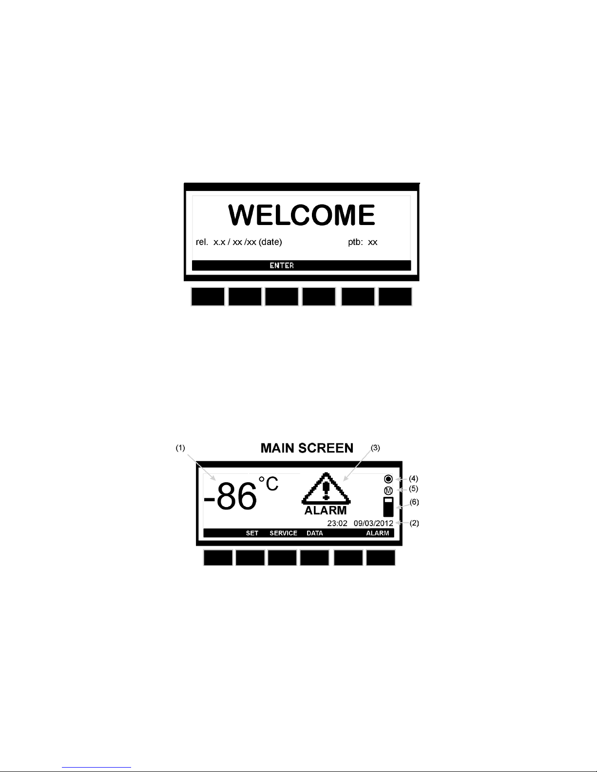
Start up:
When the appliance is connected to the power supply, the keyboard will automatically start up.
The start up view on the keyboard will show the dierent software installed on the controller of
the appliance.
Press enter to return from the start up view.
Operation – main view:
(1) The temperature in the appliance (measured by the TR3 probe)
(2) Time and date
(3) ALARM icon. Flashing by alarm. On when there has been an alarm, but the alarm is no
longer active.
(4) Logging icon. Of if no logging. On when logging
(5) Memory icon. On when the memory is 90% full. Flashing when the memory is full, and the
controller is deleting the oldest logging data.
(6) Memory bar. Shows the status of the memory.
4
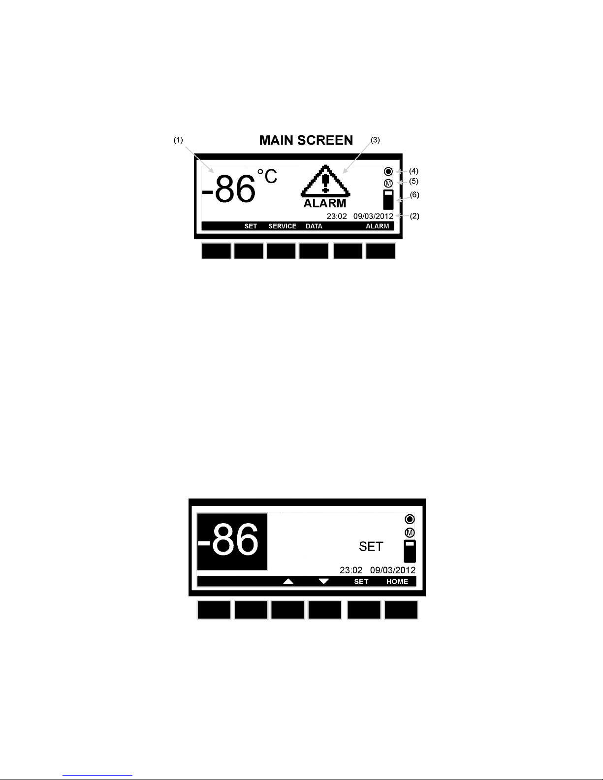
Keys – main view:
SET: Enter the Set Point menu of the temperature
SERVICE: Enter the Service menu
DATA: Enter the Data Logging menu
ALARM: Enter the Alarm menu
How to see and modify the temperature Set Point:
1. Push and immediately release the SET key: the display will show the Set Point value.
2. To modify the value push the SET key, the Set Point start ashing.
3. Use the UP and DOWN keys to modify the value.
4. To memorize the new Set Point value push the SET key again or wait 30sec.
5
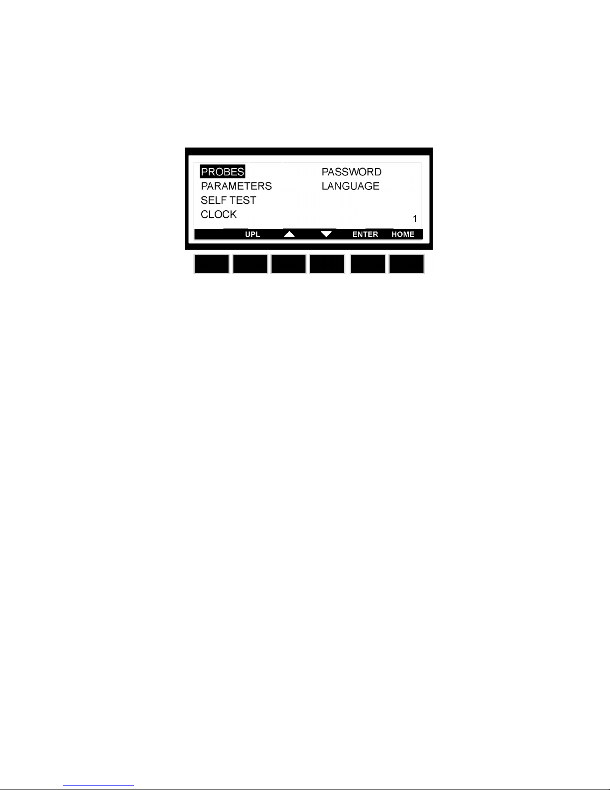
Service menu:
From the main view push the SERVICE key and the SERVICE menu is entered.
See below picture:
PROBES: Enter the probes, to see the measured temperatures. 1-4 probes is availa
ble depending on model.
PARAMETERS: Enter the setting of the parameters. Please note that changes made to the
parameters should only be made of a technician. The code to enter the Pr2
parameters is standard set to 12.
See list of parameters in page 26-29
SELF TEST: Enter the Self Test program of the controller.
CLOCK: Enter clock menu, where it is possible to change date and time.
PASSWORD: Enter the password menu, where it is possible to change the password.
LANGUAGE: Enter the language menu, where it is possible to change language.
How to change parameter:
See the parameter list at page 26-29
1. Enter the SERVICE menu
2. Select PARAMETERS sub-menu
3. Push the ENTER key
4. Select Pr1 or Pr2 sub-menu. (Pr2 require a code to enter. The code is standard set to 12).
By Pr2:
A: Push the SET key
B: Set the password/code by means of the UP and DOWN keys
C: Push the SET key
D: Push the ENTER key
5. The parameter is divided into groups. Select the group using the UP and DOWN keys
6. Select the group by pushing the ENTER key
7. Select the parameter using the UP and DOWN keys.
8. When located on the value of the parameter push the SET key
9. Set the parameter by means of the UP and DOWN keys
10. Push the SET key, to conrm and pass to the next parameter
6
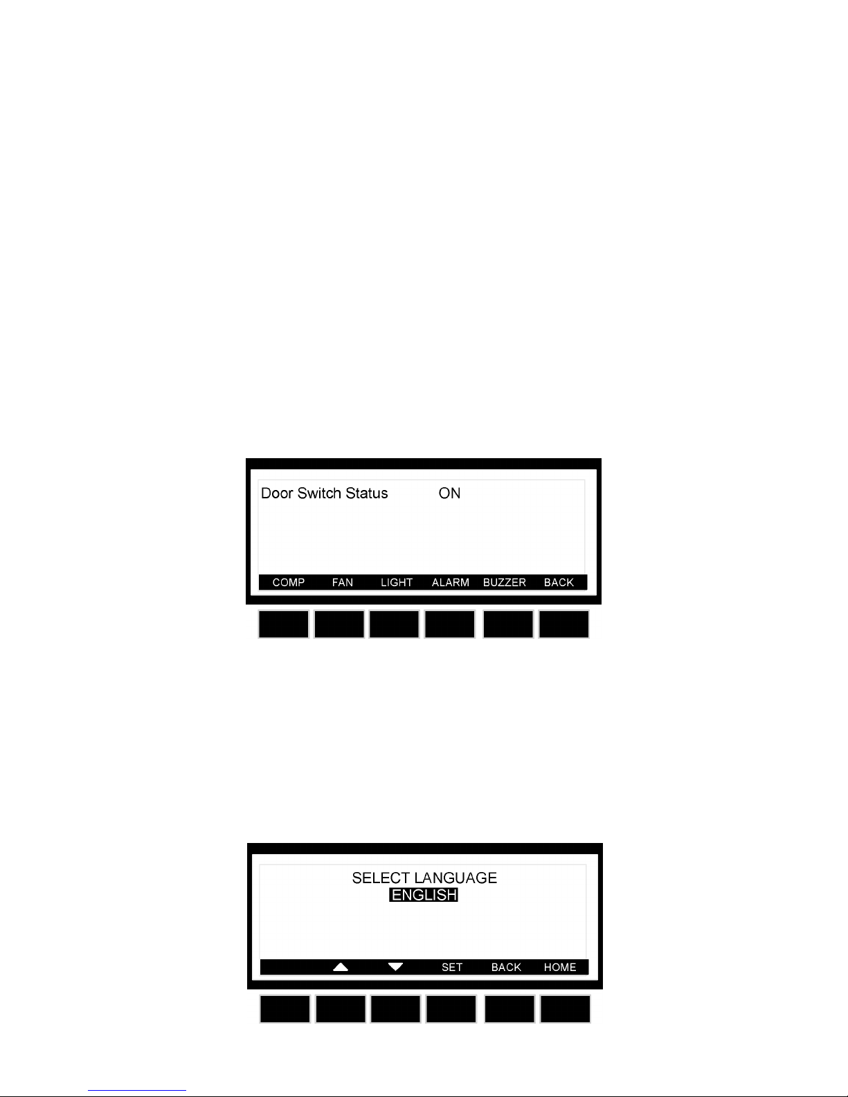
How to use the Self Test:
1. Enter the SERVICE menu
2. Select SELF TEST sub-menu
3. Push the ENTER key,
4. If PASSWORD is required, insert the password,
5. OTHERWISE the SELF TEST menu is entered directly.
6. Push the START key
7. Then push the keys to activate the correspondent loads:
a. Compressor
b. Light
c. Fan
d. Alarm
e. Buzzer
8. The display shows the status of the digital input (ON or OFF)
9. Wait 30s or push the BACK key to come back to the previous screen.
How to change language:
1. Enter the SERVICE menu
2. Select LANGUAGE sub-menu
3. Push the ENTER key and the LANGUAGE menu is entered.
4. Push the SET key and then use the UP and DOWN keys to select the language and then
the SET key to conrm it.
7
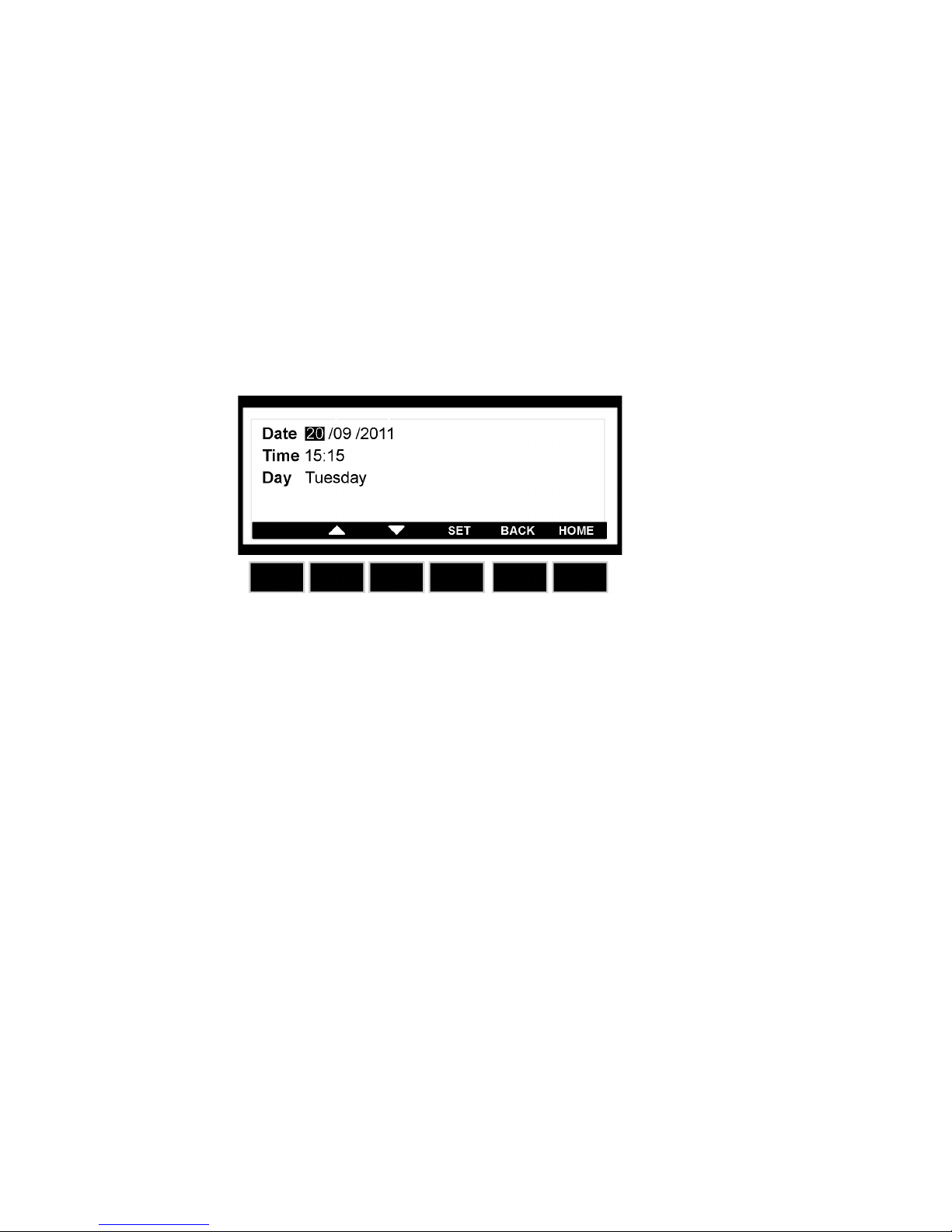
How to set time and date:
1. Enter the SERVICE menu
2. Select CLOCK sub-menu
3. Push the ENTER key.
4. Set the day by means of the UP and DOWN keys.
5. Push the SET key, to conrm and pass to the setting of time.
6. Use the same procedure as for the date.
7. Then conrm the selection by means of the SET key.
8
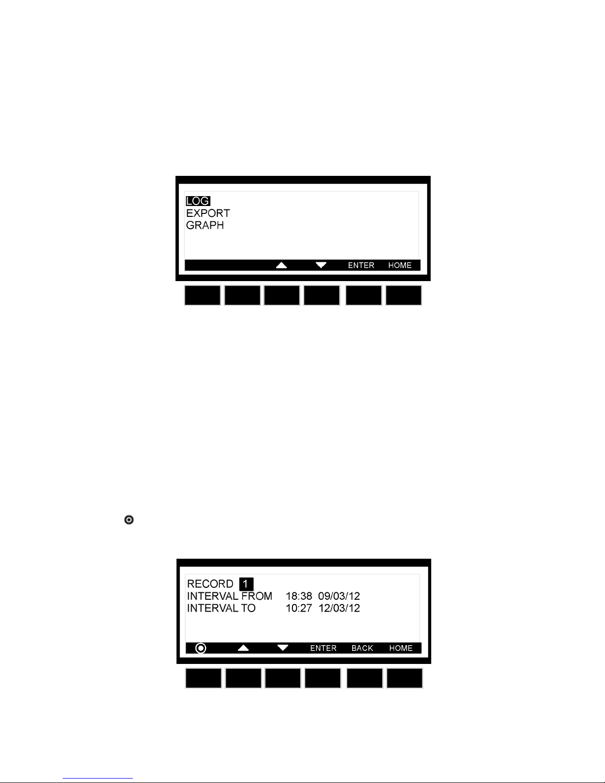
Data menu:
From the main view push the DATA key and the D ATA menu is entered.
See below picture:
LOG: Enter the data logged by the controller.
EXPORT: Export the data to an USB pen drive delivered with the appliance.
GRAPH: Enter the graph showing the temperature logged the last 24h (with a logging inter-
val of 15min.)
How to enter the log:
1. Enter the DATA menu
2. Select LOG sub-menu
3. Push the ENTER key and the LOG menu is entered.
4. By UP and DOWN keys chose the data interval to display
5. Push the ENTER key to display the selected data.
NOTE: THE KEY: IS USED TO STOP AND START LOGGING
9
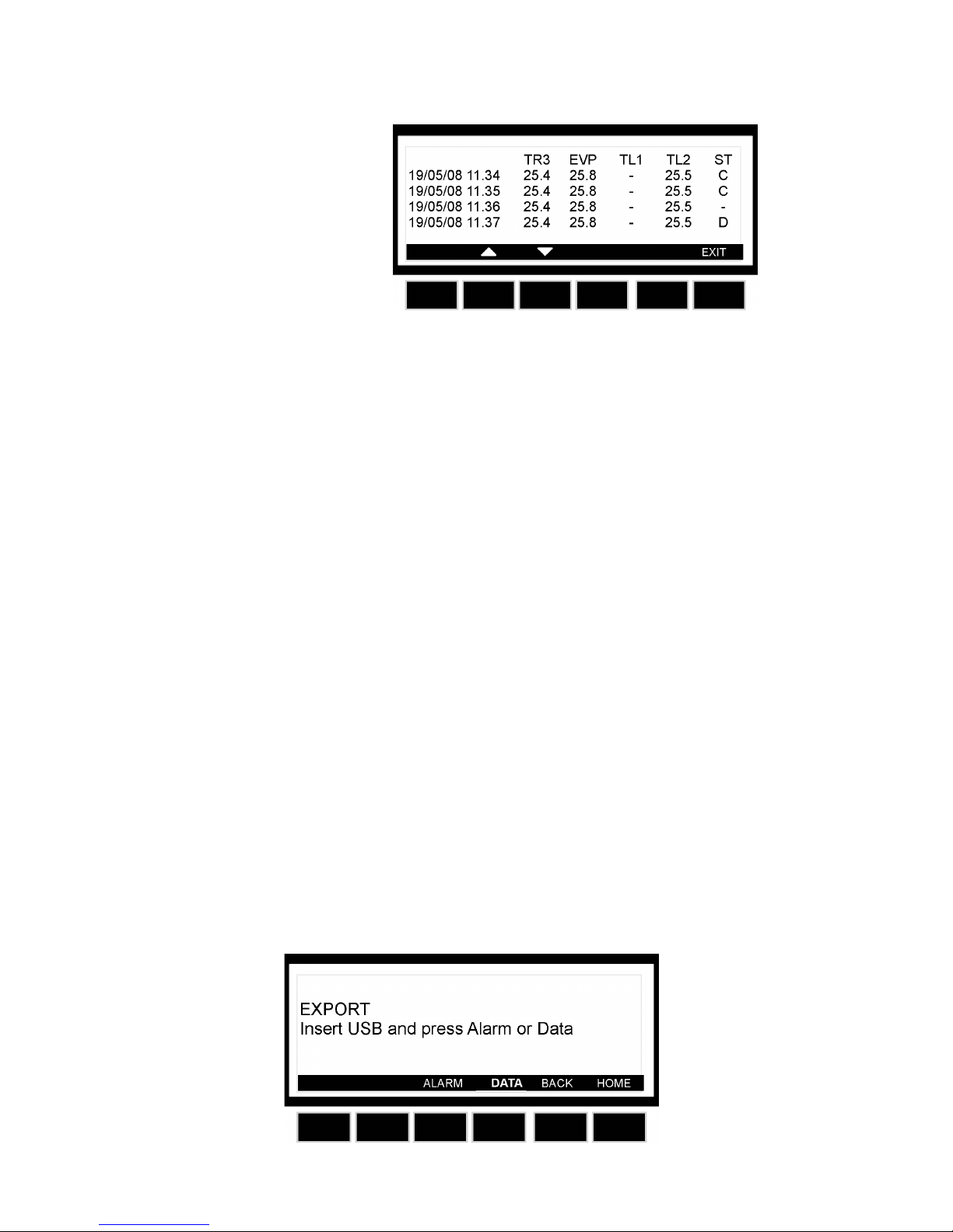
Logged data will have this layout:
Where TR3, EVP, TL1, TL2 = Value of probes.
With probe failure or absence:” - “ symbol is displayed. Please note that 1-4 probes are available depending on model.
ST: status of the controller/load
● - = operating, without any load activated;
● D = defrost running (if automatic defrost is available)
● C = compressor working
How to export data:
1. Enter the EXPORT menu
2. Insert the USB pen drive supplied by Vestfrost.
3. Select ALARM or DATA, the controller starts sending data to the pen drive, when
the export is nished the message: EXPORT - Copy completed is displayed.
The exported data will be exported as a CSV-le (Comma Separated Values). This le can be
used in ex. Excel for making graphs.
IMPORTANT: during the download don’t remove the USB pen drive: this action could
damage the data les and USB pen drive itself.
WARNING: leave the USB pen inserted only for the time necessary to export data then
remove.
WARNING: if a not compatible USB pen drive is used it can cause a reset of the con-
troller
10
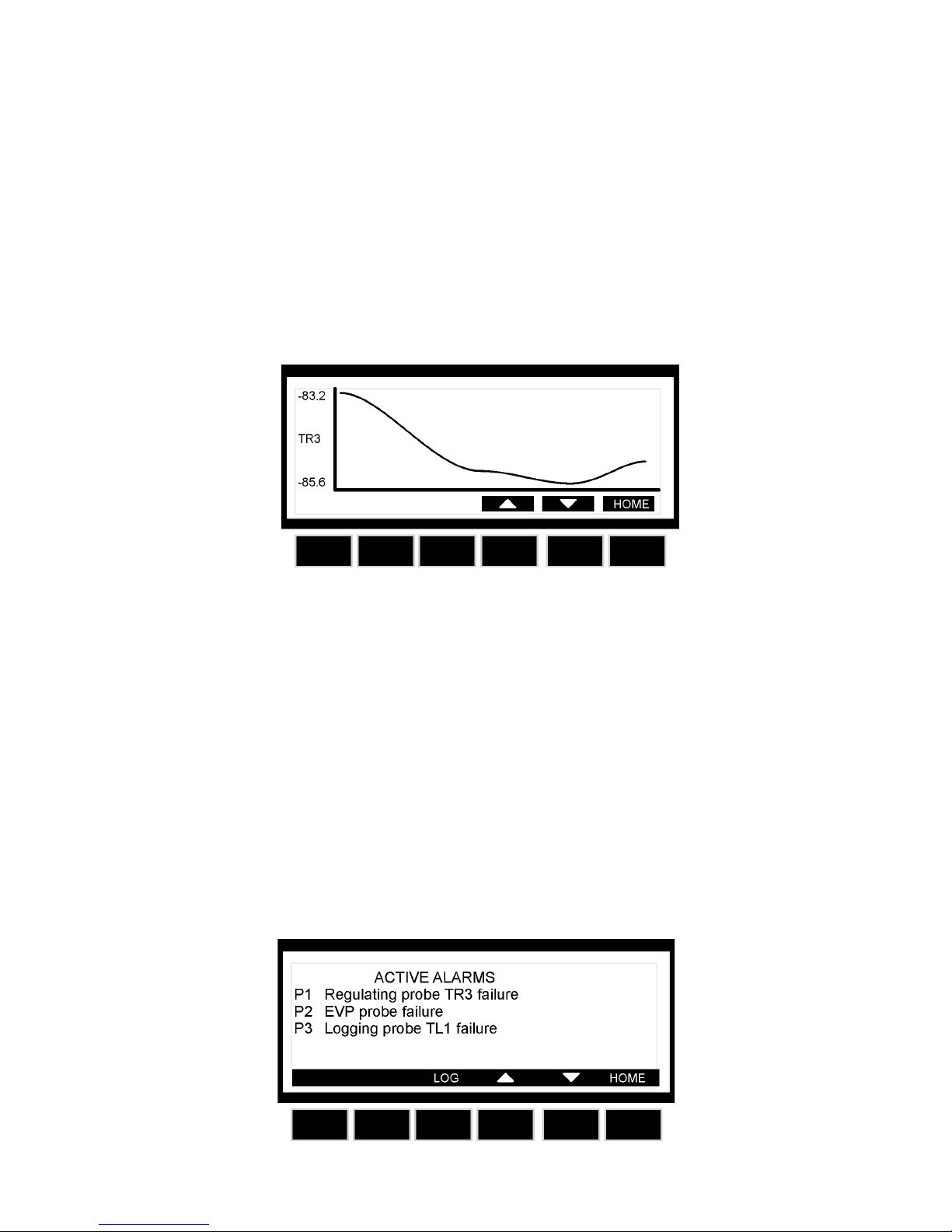
How to enter the Graph:
1. Enter the DATA menu
2. Select GRAPH sub-menu
3. Push the ENTER key and the GRAPH menu is entered.
4. By UP and DOWN keys chose the probe that has to be displayed.
5. Push the HOME key to get back to the main view.
NOTE: A graph is erased when the controller is switched o.
Alarm menu:
If the alarm icon is ashing on the main display, an alarm is occurring.
If the alarm icon is displayed but not ashing on the main display, an alarm is occurred and
recovered.
Once the alarm signal is detected the buzzer can be silenced by pressing any key.
Active alarms:
1. Push the ALARM key to enter the alarm menu.
2. The alarm menu displays the active alarm with the following layout:
a. First column = alarm code
b. Second column = alarm description
11
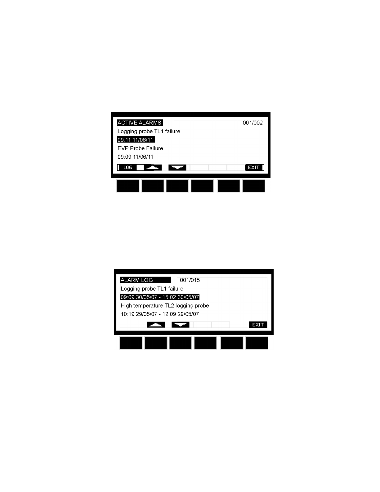
3. Push the LOG button to enter the ACTIVE ALARM LOG.
This menu contains all the information concerning the active alarms. In the rst line, it is
displayed how many alarms are happening.
4. It’s possible to move through the alarms by the UP and DOWN keys.
5. Push the LOG button to enter the ALARM LOG. This menu contains all the memorized
alarms. For each alarm the starting time and date and the nish time and date are recorded.
 Loading...