

Page 1
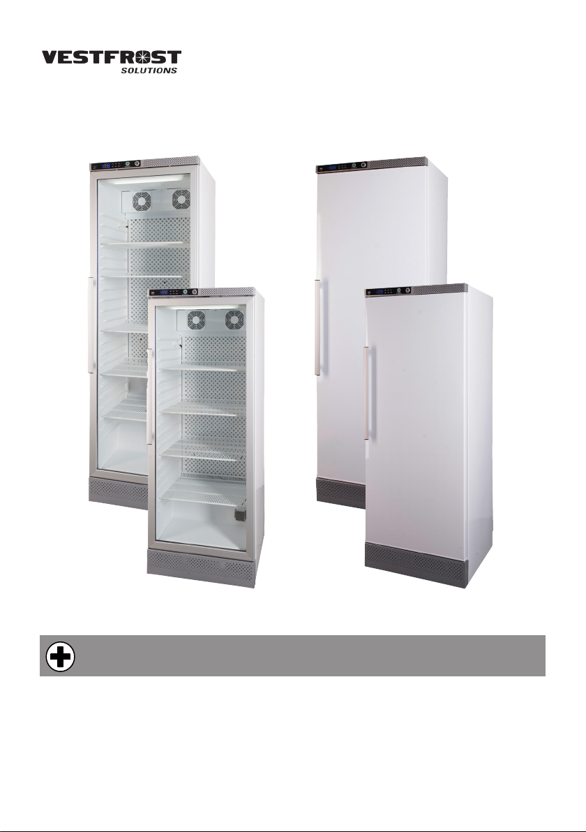
AKG/S 337 / 397
GB Instructions for use
DE Bedienungsanleitung
FR Mode d’emploi
Page 2

GB
Warning
As the appliance contains a ammable refrigerant, it is essential to
ensure that the refrigerant pipes
are not damaged.
The quantity and type of the
refrigerant used in your appliance is indicated on the rating
plate.
Standard EN378 species that
the room in which you install your
appliance must have a volume of
1m³ per 8 g of hydrocarbon refrigerant used in the appliances.
This is to avoid the formation of
ammable gas/air mixtures in
the room where the appliance is
located in the event of a leak in
the refrigerant circuit.
WARNING:
Keep ventilation openings in the
appliance’s cabinet or in the builtin structure clear of obstruction.
WARNING:
Do not use other mechanical
devices or other means to accelerate the defrosting process
than those recommended by the
manufacturer.
WARNING:
Do not damage the refrigerant
system.
WARNING:
Do not use electrical appliances inside the refrigerated stor-
age compartment, unless they
are of a type recommended by
the manufacturer.
WARNING:
Do not expose the appliance to
rain, and secure not splashing
water when cleaning the oor.
WARNING:
This appliance is not intended
for use by children or inrm
persons unless they have been
adequately supervised by a
responsible person to ensure
that they can use the appliance
safely. Children should be supervised to ensure that they do not
play with the appliance.
WARNING:
Do not store explosives, such
as aerosol cans with ammable
propellants in the unit.
WARNING:
Danger risk of re or explosion if
ammable refrigerant are used.
To be repaired only by trained
personnel.
2
Page 3

WARNING:
When positioning the appliance,
ensure the power cord is not
trapped or damaged.
WARNING:
Do not locate multiple portable
socket-outlets or portable power
supplies at the rear of the appliance.
WARNING:
Sharp edges on cabinet, compressor compartment, evaporator, ventilation cover and on
internal equipment can occur.
Please be aware to avoid injury.
WARNING:
The condenser on the back of
the appliance will in some cases
have a hot surface. Please be
aware to avoid injury.
WARNING:
The appliance must be connected to power minimum 12
hours before using it for storage
of medicine.
GB
● Always keep the keys in a separate place
and out of reach of children.
● Do not step on the lower panel to reach
medicine in the top of the appliance.
● Before servicing or cleaning the appli-
ance, unplug the appliance from the
mains or disconnect the electrical power
supply.
● If the supply cord is damaged, it must be
replaced by the manufacturer, its service
agent, or similarly qualied persons in
order to avoid a hazard.
● Relevant for Australia: Supply cord
tted with a plug complies with AS/NZS
3112.
● Frost formation on the interior evaporator
wall and upper parts is a natural phenomenon. Therefore, the appliance should
be defrosted during normal cleaning or
maintenance.
● Please note that changes to the appli-
ance construction will cancel all warranty
and product liability.
● This device is intended to be
used exclusively for medical
products.
● If medicine is spilled in the appliance
or the defrost water canal is has to be
cleaned immediately to avoid the medicine to evaporate to the surroundings.
● If the instructions is lost please contact
your supplier of the appliance to have a
new instruction for use.
● If service needed to this device, please
be aware of only using service personnel with education in handling medical
devices.
3
Page 4

GB
Contents
Warning ......................................................2
About ........................................................5
Get to know your refrigerator ......................6
Before use ..................................................7
Electrical connection ...................................7
Installation and start-up ..............................8
Placement and installation ..........................9
Levelling the appliance ............................. 11
Probe bottle .............................................12
Interior tting .............................................13
Mounting of drawer dividing system ........14
Ordinary use .............................................15
Porthole ....................................................15
Voltage free contact .................................16
Safety Thermostat ....................................17
Reversing the door ...................................21
Defrosting, cleaning and maintenance .....24
Fault nding ..............................................25
Warranty, spare parts and service ............26
Disposal ....................................................27
4
Page 5
About
Dear Customer. Congratulations with
your new AKG/S 337/397. This pharmacy
refrigerator is meant for reliable storage of
medication and other products needed to
be stored at a stabile temperature between
2-8 degrees C. The parameters are as following.
Temperature range 2 °C – 8 °C
Fabric Set Point 4
Ambient Temperature 15 – 30 °C
(35 ° C for solid
doors)
Relative humidity 70 %
(75 % for solid
doors)
Number of probes 3 – 5 depending
on equipment of
the device
GB
As standard, the device is equipped with
3 sensors. One to control the compressor,
one to control the defrost function and one
in the top for information about temperature
at loading limit.
Some model has a reference probe bottle
installed with a fourth probe and a fth
probe for a safety thermostat.
The climate class can be seen at the rating
plate.
5
Page 6
GB
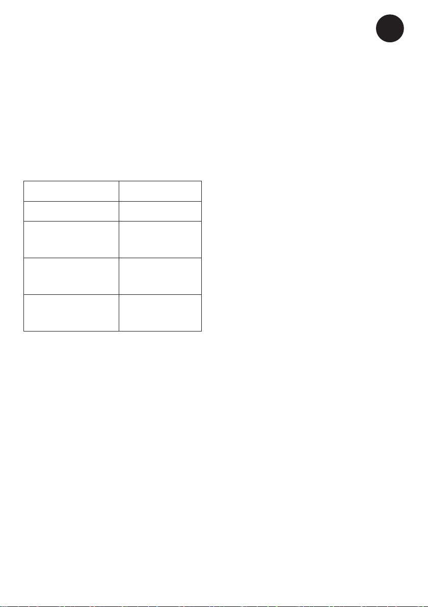
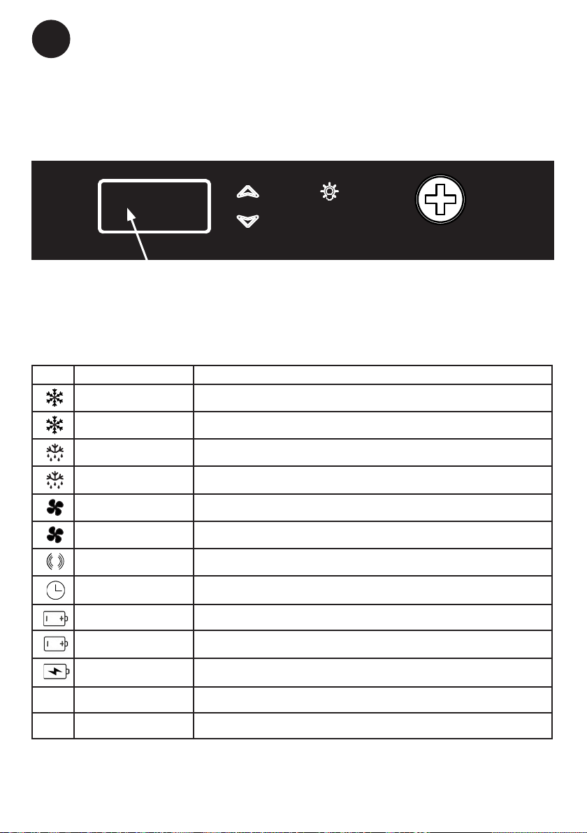
Get to know your refrigerator
SET
DATAREC
Display/Keyboard
Lock
LED Light
Fans (on the rear wall)
Rating plate
Stacking mark
Adjustable shelf
PHARMA
Adjustable drawer
(optional)
Door handle
Probe bottle
Bottom shelf
Wheel or feet
g. 1
6
Page 7
GB
Before use
Before turning on the appliance, please
read the following instructions carefully as
they contain important information regarding safety, installation, operation and
maintenance. Please keep the instructions
for future reference.
On receipt, please check the appliance to
ensure it has not been damaged during
transportations. Damage from transportation should be reported to the distributor. Do
not use the appliance before all commercial
issues have been claried.
The foil on the shelves must be removed
before cleaning and using the unit. Clean
the inside of the cabinet using warm water
with a mild detergent. Rinse with clean
water and dry thoroughly (see cleaning
instructions). Use a soft cloth.
If the appliance has been laid down during
transportation, or if it has been stored in
cold surroundings (colder than +5°C), it has
to stabilize in an upright position for at least
an hour at normal conditions before being
switched on.
Note: If it is necessary to lay down the
appliance, the door must face upwards
and the appliance must be enclosed in the
original packaging.
Electrical connection
Wiring and connections in power supply
systems must be in accordance with all
applicable (local and national) electrical
codes. Consult these codes lengths and
sizes prior to cabinet installation.
This appliance complies with relevant EU
directives including Low Voltage Directive
2014/35/EU and Electromagnetic Compatibility Directive 2014/30/EU.
The socket should be freely accessible.
Connect the appliance only to 220/240 V
/ 50Hz alternating current via a correctly
installed earthed socket.
The socket must be fused with a 10 A or
13 A fuse.
If the appliance is to be operated in a
non-European country, check on the rating
plate whether the indicated voltage and
current type correspond to the values of
your main supply.
Data regarding voltage and absorbed
power / current are given on the rating
plate.
The power cord may be replaced by a
technician only.
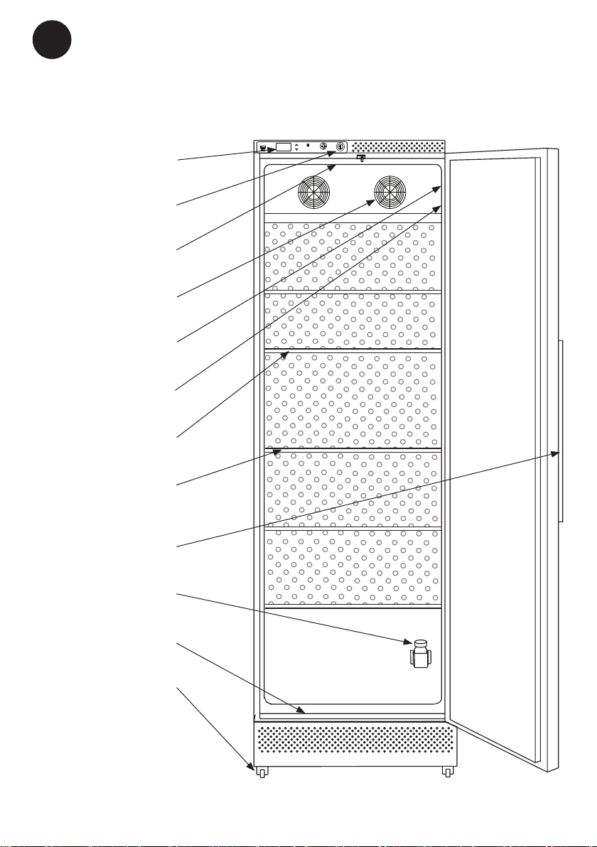
The rating plate provides various technical information as well as type and serial
number.
Product number
g. 2
7
Page 8

GB
Installation and start-up
Battery backup
This appliance is equipped with a battery
back up system. Please activate the battery
backup before nal placement A fuse is
placed in the bag with helping materials.
Take this fuse and insert is as illustrated on
the picture.
Fuse
g. 3
NOTE! The battery backup system does
not supply the cooling system
with power. When starting up the
appliance for the rst time it is
necessary to switch on the battery
backup system.
Battery backup function
The battery backup system supplies the
controller and keyboard with power at
power failure. This makes it possible to
supervise the temperatures in the unit during the power failure. The battery backup
system makes it possible to supervise the
temperatures for 48 hours.
After a power failure and at the rst start
up the battery needs to be recharged. To
regain the full capacity the battery will be
reloading for 10 days.
NOTE! The battery for back up should be
changed every third year to secure
48 hours of back up. Please put
this change in the maintenance
schedule for every third year.
8
Page 9

Placement and installation
GB
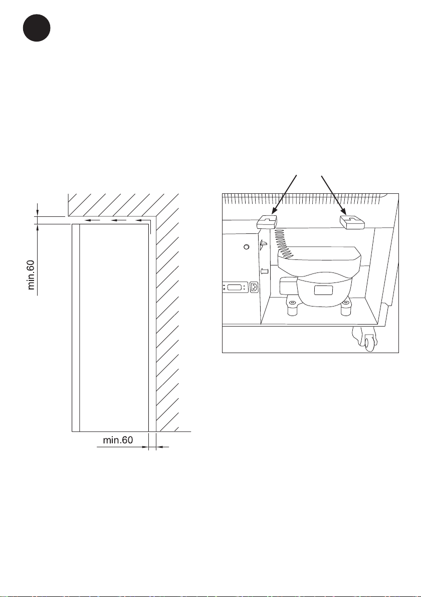
The appliance viewed from
above
If the appliance is placed beside a wall,
there must be sucient room for its door to
be opened wide enough to allow the shelf to
be pulled out (g. 4)
g. 4
Side by side
In side-by-side arrangements there must be
at least 60 mm between each unit on each
side of the cabinets, to ensure the doors
can be opened freely (See g. 5)
Setting up
It is important that the appliance is absolutely level. It can be levelled by screwing
the adjustable feet of the appliance up or
down.
Use a spirit level to check that the appliance
is absolutely level sideways.
If the appliance is placed on a soft sur-
face, e.g. oorboards or a carpet you must
recheck whether the appliance is still level
after a period of time as the underlying
surface may yield under the weight of the
appliance.
g. 5
9
Page 10
GB
Ventilation
It is important that the appliance is well
ventilated and that air can circulate freely
above, below and around it.
The gurs (g. 4-7) illustrate how the necessary air circulation around the appliance is
ensured.
Ventilation guard
The guards on the rear of the appliance
ensure sucient air circulation. The guards
must be tilted down when the cabinet is
installed.
Guards tilted down
g. 7
g. 6
10
Page 11
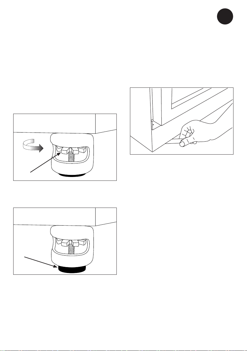
Levelling the appliance
GB
Depending on the equipment of the appliance, the device is either installer with 4
wheels that can be levelled, or with two feet
installed in front of the cabinet.
Wheels
Install unit and rotate nut clockwise to move
foot to oor. See g 8-10
g. 8
Feet
1. Level the appliance sideways by screwing the adjustable feet up or down using
the accompanying spanner. se g 10
g. 10
2. Check that the appliance is absolutely
level.
If the appliance is to be placed on a soft
surface, e.g. oorboards or a carpet, it is
best to recheck whether the appliance is
still level after a period of time as the underlying surface may give under the weight of
the appliance.
g. 9
11
Page 12
GB
PHARMA
DATAREC
SET
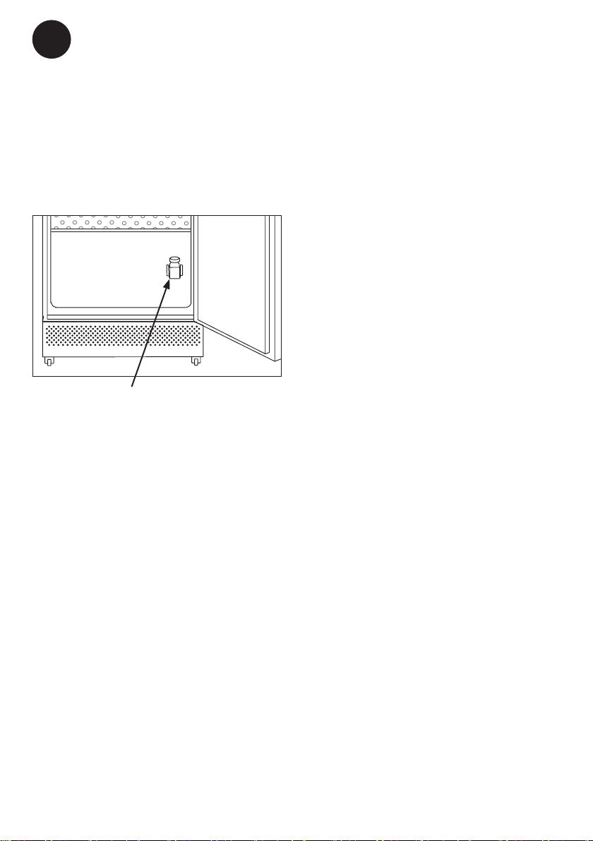
Probe bottle
Some models have a probe bottle installed.
Before starting up the appliance, ll the
probe bottle with a mixture of 50% water
and 50% ethanol.
Probe bottle
g. 11
12
Page 13
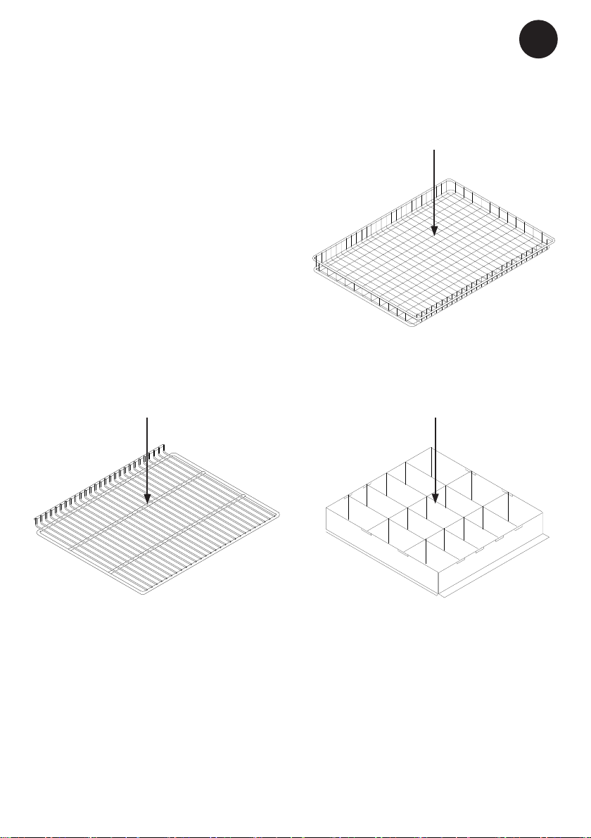
Interior tting
GB
As a standard, the device is equipped with
wire shelfs. The possible equipments is
shown at gure 12-14.
Max. 36 kg
Max. 36 kg
g. 13
Max. 10 kg
g. 12
OBS: Max. 7 drawers in a cabinet.
g. 14
13
Page 14
GB
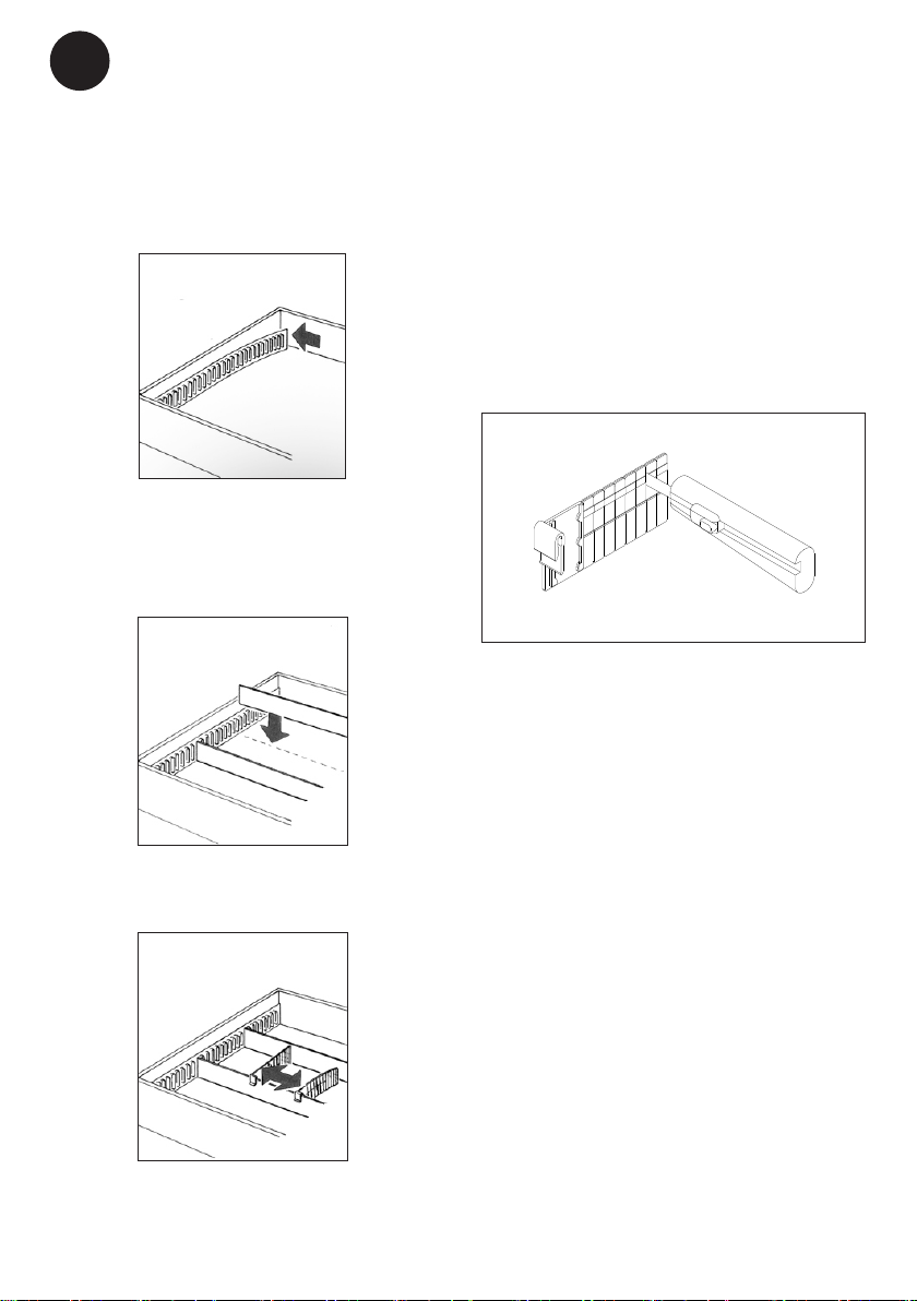
Mounting of drawer dividing system
Drawers are optional.
1. The Rail Holder with double adhesive
tape is mounted inside the rear and front
of the drawer.
Adjustment of dividing parts
Integrated breakpoints allows storage of
individual products. Adjust the dividing part
as follows.
(See g 15) Cut into the appropriate seam
and break of the excess part.
g. 15
2. Put in the rails.
3. Snap on the dividers and slide it.
14
Page 15
GB
Ordinary use
Inside the cabinet. Avoid keeping the door
open for long periods unnecessarily.
The appliance is not designed to be used
for cooling warm products. Placing such
items in the cabinet may cause the temperature of products already in the cabinet to
rise. Important: Note that the door opening
frequency will inuence the temperature.
Medicine may not be placed higher than
the red and white stacking mark in the
top of the appliance, because it will
prevent air to circulate and keep the appliance cold. Further more medicine at
the bottom shelf may not touch the sides
of the interior. Both things will prevent
an even temperature in the appliance.
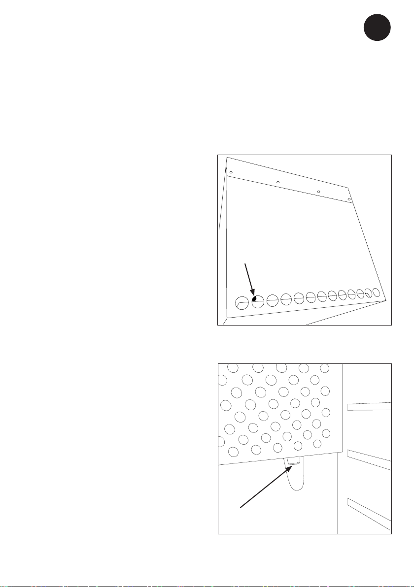
Porthole
The device is equipped with a porthole. Just
put in the probe in the top as illustrated and
it will appear inside the refrigerator below
the cover plate for the evaporator as show
on the next gure.
Porthole
g. 16
15
Porthole
g. 17
Page 16
GB
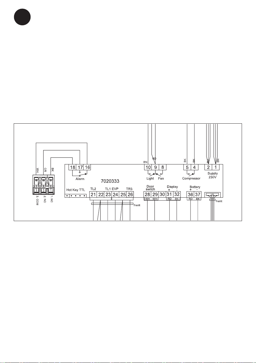
Voltage free contact
Your device is equipped with an EXTERNAL ALARM connection. The connection is
executed as DRY Contact.
The 3-pole connection has an NC (pin
1-3) and a NO connection (pin 1-2) and is
used to connect a customer-specic alarm
system.
XW737K
16
g. 18
Page 17
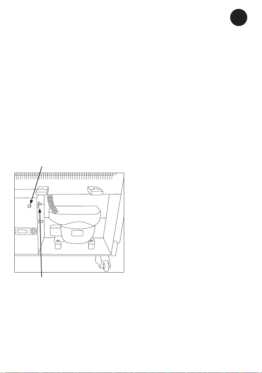
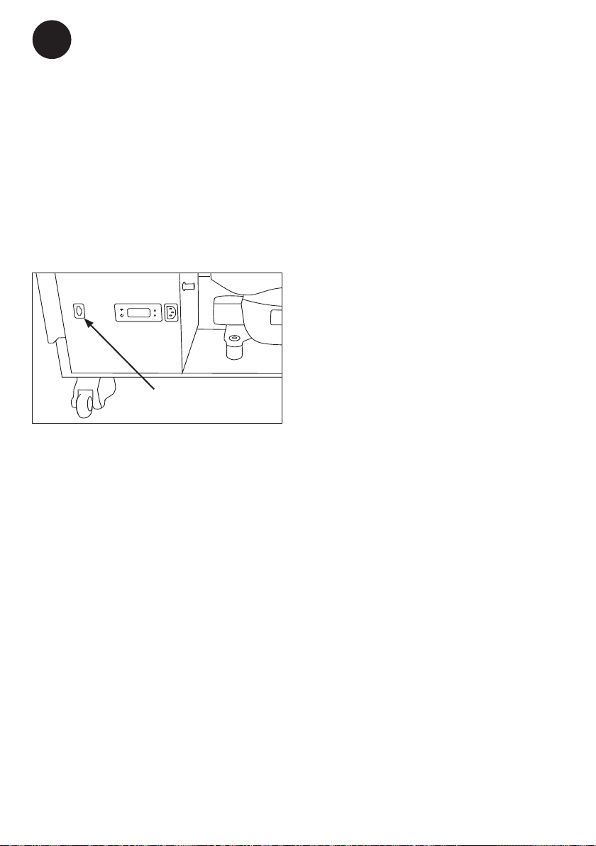
Safety Thermostat
The device contains a safety thermostat
which ensures control of the compressor if
the refrigerator for a reason should become
too cold. It is recommended to test the
safety thermostat at least once a year.
In the engine room, there is a contact
for test of the safety thermostat (see the
picture). When the compressor is running,
push this button. In 10 seconds, the compressor will stop and the green light in the
indicator lamp will be turned o.
Indicator for test of safety thermostat
GB
Contact for test of
safety thermostat
g. 19
17
Page 18
GB
!
DATAREC
SET
PHARMA
Controller. Operation and function
User interface
Display
LEDS
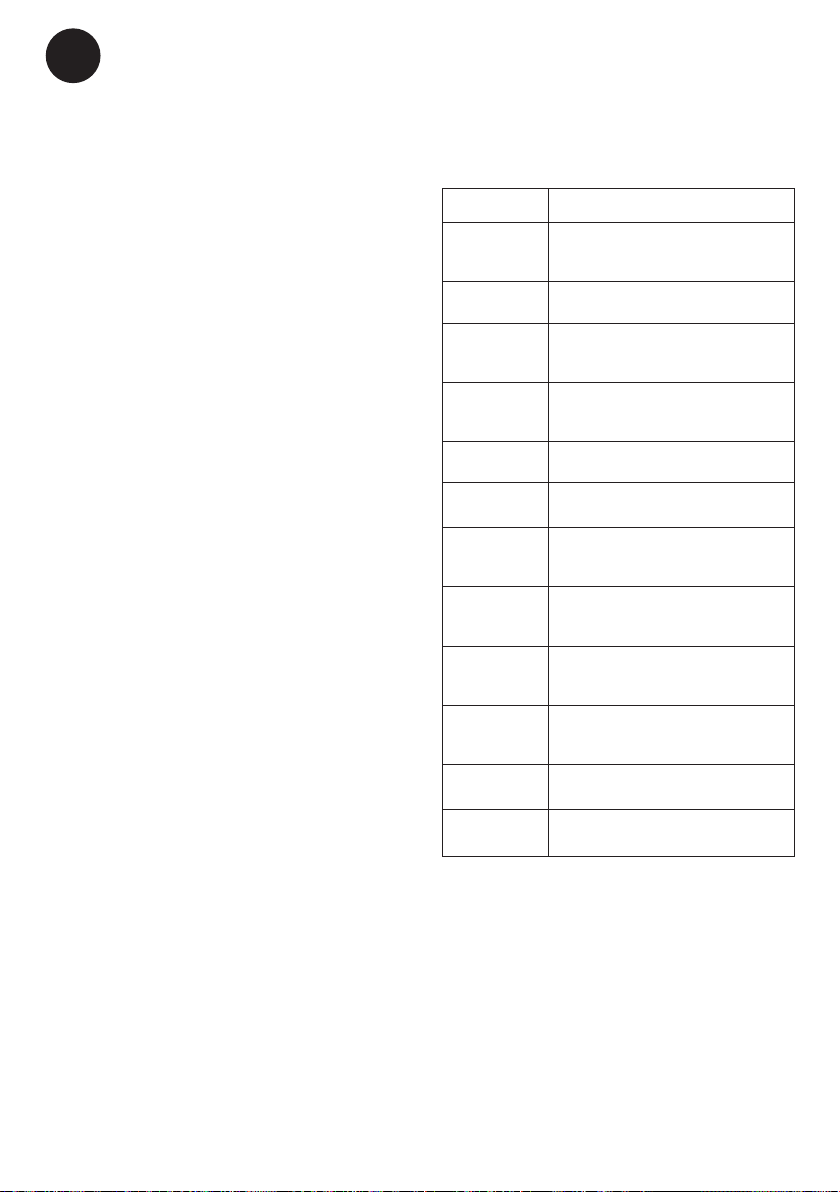
Each LED function is described in the following table.
LED MODE Function
ON Compressor enabled
Flashing Anti-short cycle delay enabled
ON Defrost enabled
Flashing Drip time in progress
ON Fans enabled
Flashing Fans delay after defrost in progress
ON An alarm is occurring
ON Recording activated
ON Battery is fully charged
Flashing Battery is beeing charged
Flashing Charging problem or battery failure
g. 20
°C/°F ON Measurement unit
°C/°F Flashing Programming phase
18
Page 19

Bottons
To display target set point; in programming mode it selects a parameter or conrm an opera-
SET
tion.
To enter fast access menu In programming mode it browses the parameter codes or increases
the displayed value. (DOWN); n programming mode
In programming mode it browses the parameter codes or decreases the displayed value. Push
it for 3s to start a manual defrost
Export data from button
DATA
To switch o the light in the door (only models with light in the door
Log activation and deactivation from button (Password protected)
REC
GB
How to see and modify the
setpoint
How to: See the Set point
1. Push and immediately release the SET
key: the display will show the Set point
value.
2. Push and immediately release the SET
key or wait for 60 sec to display the temperature in the unit.
How to: Change the Set point
1. Push the SET key more than 2 sec to
change the Set point value.
2. The value of the set point will be displayed and the “°C” LED will start blinking.
3. To change the Set value push the UP or
DOWN arrows within 60 sec.
4. To save the new set point value, push the
SET key again and wait for 3 sec.
NOTE: To exit without making any change
to the set point, push the SET key or
wait 60 sec.
Clock settings and RTC alarm
reset
1. Push the UP key once, to acces the
menu.
2. The display shows H∩, then push SET.
3. The parameters for setting time and date
occurs. To set the parameter push SET,
push the UP or DOWN button to change
the parameter. Conrm by pushing SET.
The time and date parameters:
Hur: hour
∩in: minutes
Udy: weekday
dAy: date
∩on: month
yEA: year
To exit: Press SET + UP keys for about 10
sec. or wait 60 sec.
19
Page 20
GB
How to export data and alarms
to USB
1. Insert the USB key
2. Push the DATA key for more than 3 sec.
3. Controller starts uploading data to USB
4. At the end the following message will be
displayed:
a.“End” if everything is ok
b.“Err” if exporting has not taken place.
Alarms
The controller memorizes the last 100
alarms happened, together with their start
and nish time. It’s possible to export the
alarms as described in the previous chapter.
Active alarm
Controller will show active alarm alternated
with the temperature inside the unit.
Alarm signals
The alarm message is displayed until the
alarm condition is recovered.
All the alarm messages are showed alternating with the temperature in the unit.
Except for the “PF1” which is ashing.
Alarms at start up
When the unit is started up the rst time
the alarm will sound/show until the unit has
reached the upper temperature alarm limit.
This can take several hours.
It is possible to mute the alarm for 30 min-
utes. See below explanation.
Message Cause
“PF1” Regulating probe TR3
failure
“PF2” EVP Probe Failure
“PF3” Logging probe TL1
failure
“PF4” Logging probe TL2
failure
“HA1” TR3 High Alarm
“LA1” TR3 Low Alarm
”HA3” High temperature
alarm probe TL1
”LA3” Low temperature
alarm probe TL1
”HA4” High temperature
alarm probe TL2
”LA4” Low temperature
alarm probe TL2
“dA” Door Open Alarm
“CA” Serious Alarm
Muting the alarm
When an alarm occurs any button on the
display can be pushed to mute the alarm for
30 minutes. The alarm will still be visible at
the display and the red LED will continue to
ash.
20
Page 21
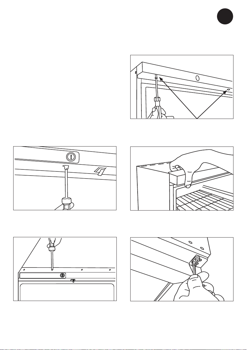
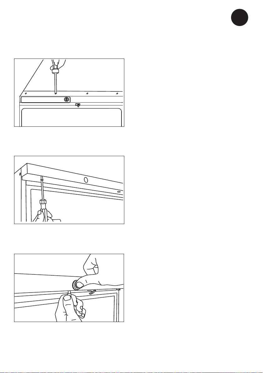
Reversing the door
Remember to unplug the unit.
Note:
the unit may not be placed on its back.
OBS:
Left-side top hinge is required for reversing
the door. Request a spare parts list
GB
3. Remove the 2 screws below the panel.
1. Remove the lock pin using a at-headed
screwdriver.
2. Remove the top panel. Remove the 4
screws at the top op the panel.
4. Tilt the top panel forwards to remove it
Place the panel upside down on top of
the unit).
5. Remove upper hinge (use hex key to the
2 screws) and the torsion spring.
21
Page 22
GB
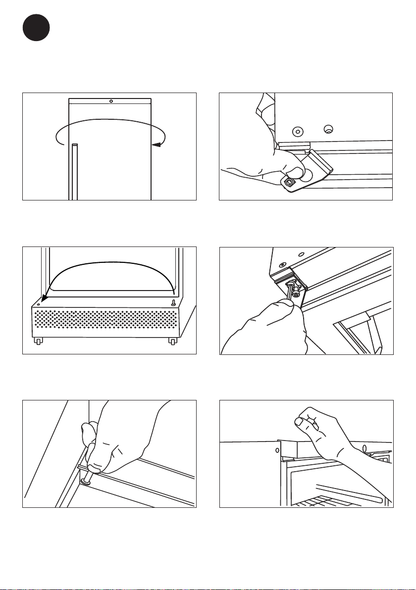
6. Move the door handle to the opposite
side.
7. Move the hinge pin to the opposite side
of the bottom hinge.
9. Fit the left-side top hinge (required
spare part)
10. Secure the top hinge in position.
9. Insert the hinge pin and the torsion
spring into the the top of the door on the
opposite side.
11. Bring the top panel into place.
22
Page 23
12. Remount the top panel with 4 screws at
the top op the panel...
GB
15. After reversing the door, it is important
to check that the sealing strip provides
a tight seal all the way round. If it does
not, carefully heat the strip all the way
round using a hair dryer. Then ease the
strip outwards slightly so that it forms a
tight seal against the cabinet. Be careful not to heat the strip so much that it
melts!
13. .. and the 2 screws below the panel.
14. Ret the lock housing and lock pin.
23
Page 24

GB
Defrosting, cleaning and maintenance
Automatic defrosting.
The refrigerator is defrosted automatically.
Defrost water runs through a pipe and is
collected in a tray above the compressor
where the heat generated by the compressor causes it to evaporate. Defrost water
can be collected from behind, where there
is a container to collect it. The container
should be emptied regularly.The defrost
water tray should be cleaned when needed
or at least once a year.
Cleaning and maintenance
Before cleaning, disconnect the power sup-
ply and remove all loose ttings.
The appliance is best cleaned using warm
water (max. 65°C) with a little mild, perfume-free detergent. Never use cleaning
agents that scour. Use a soft cloth. Rinse
with clean water and dry thoroughly. It is
important to prevent water from entering the
control panel.
Add a few drops of disinfectant to the
defrost water drain a couple of times a year,
and clean the drain using a pipe cleaner or
similar. Never use sharp or pointed implements.
When disinfecting the appliance always
consult professional persons to ensure that
the disinfectant used is approved in your
country, and to ensure right method is used.
For use in this appliance, we recommend
the following base of disinfectant: alcohols
and aldehydes. Chlorine and peracids can
also be used, but please be aware that
chlorine and peracids based products can
inect on the surface of materials, there for
a careful washing o with clear water and
wiping o, after disinfecting, is very impor-
tant.
The sealing strip around the door must be
cleaned regularly, at least twice a year. to
prevent discolouration and prolong service life. Use clean water. After cleaning
the sealing strip, check that it continues to
provide a tight seal.
It is recommended that the wire and tubular
condensers on the rear of the appliance are
cleaned.
Dust collecting on the condenser on the
rear of the cabinet, the compressor and in
the compressor compartment is best removed using a vacuum cleaner. This must
be done regularly, at least four times a year
OBS: If the appliance is not to be used for
any length of time, switch it o, disconnect
the power supply, empty it, clean the inside
and leave the door open to allow air circulation and prevent smells.
WARNING: Secure not splashing water
when cleaning the oor.
24
Page 25

Fault nding
Fault Possible cause Remedy
Screen of keybord is
not lit.
Power failure; the fuse is blown;
the appliance is not plugged in
correctly, the power is cut.
Check that power is connected.
Reset the fuse
GB
Temperature in refrigerator too high
Temperature in refrigerator too low.
Vibration or bothersome noise
Compressor runs
continuously.
Display or alarm log
shows ”RTC” error
The ventilation grille is blocked.
The door is not closed properly.
The quantity of items placed in
the freezer at a time is greater
than the capacity of the appliance.
The temperature setting is too
high
The temperature setting is too
low
The appliance is not level. Level the appliance (For model
The temperature setting is too
low.
Too high room temperature.
The date and time is not set. Please set the date and time.
Ensure unhindered air circulation
Close the door and wait 15 min.
Wait 15min
Lower the temperature setting.
Raise the temperature setting
with adjustable feet: use a spirit
level)
Raise the temperature setting.
Ensure adequate ventilation
25
Page 26

GB
Warranty, spare parts and service
Warranty disclaimer
Faults and damage caused directly or
indirectly by incorrect operation, misuse,
insucient maintenance, incorrect building,
installation or mains connection. Fire, accident, lightening, voltage variation or other
electrical interference, including defective
fuses or faults in mains installations.
Repairs performed by others than approved
service centres and any other faults and
damage that the manufacturer can substantiate are caused by reasons other than
manufacturing or material faults are not
covered by the warranty.
Please note that changes to the construction of the appliance or changes to the
component equipment of the appliance will
invalidate warranty and product liability, and
the appliance cannot be used lawfully. The
approval stated on rating plate will also be
invalidated.
Transport damage discovered by the buyer
is primarily a matter to be settled between
the buyer and the distributor, i.e. the distributor must ensure that such complaints
are resolved to the buyer’s satisfaction.
Before calling for technical assistance,
please check whether you are able to
rectify the fault yourself. If your request for
assistance is unwarranted, e.g. if the appliance has failed as a result of a blown fuse
or incorrect operation, you will be charged
the costs incurred by your call for technical
assistance.
Spare parts
When ordering spare parts, please state the
type, serial and product numbers of your
appliance. This information is given on the
rating plate. The rating plate contains various technical information, including producttype and serial numbers.
Product number
g. 2
26
Page 27

Disposal
GB
Information for Users on Collection
and Disposal of Old Equipment and
used Batteries
These symbols on the products,
packaging, and/or accompanying
documents mean that used electrical and electronic products and
batteries should not be mixed with
general household waste. For proper
treatment, recovery and recycling
of old products and used batteries,
please take them to applicable collection points, in accordance with your
national legislation and the Directives
2002/96/EC and 2006/66/EC.
By disposing of these products and
batteries correctly, you will help to
save valuable resources and prevent
any potential negative eects on
human health and the environment
which could otherwise arise from
inappropriate waste handling.
For more information about collection and recycling of old products and
batteries, please contact your local
municipality, your waste disposal
service or the point of sale where you
purchased the items.
Penalties may be applicable for incorrect disposal of this waste, in accordance with national legislation.
For business users in the European Union.
If you wish to discard electrical and
electronic equipment, please contact
your dealer or supplier for further
information.
Information on Disposal in other
Countries outside the European
Union
These symbols are only valid in the
European Union. If you wish to discard this product, please contact your
local authorities or dealer and ask for
the correct method of disposal.
Note for the battery symbol:
This symbol might be used in combination with a chemical symbol. In this
case it complies with the requirement
set by the Directive for the chemical
involved.
27
Page 28

DE
Warnung
Da ein brennbares Gas als Kältemittel in diesem Gerät dient, ist
es wichtig sicherzustellen, dass
kein Teil des Kühlkreislaufs oder
der Röhren beschädigt ist.
Die Menge von Kältemittel im
Gerät ist auf dem Typenschild
angegeben.
Der Standard EN378 speziziert,
dass der Raum, in dem das Gerät
installiert wird, ein Volumen von
1m³ pro 8 g Kohlenwasser sto-
Kältemittel, das im Gerät verwendet ist, haben soll. Dies ist zu beachten, um die Bildung von leicht
entzündlichen Gasgemischen in
dem Raum, wo das Gerät installiert ist, zu vermeiden, falls eine
Undichtigkeit des Kuhlkreislaufs
entsteht.
WARNUNG:
Decken Sie die Lüftungsönungen im Kabinett am Gerätes oder
am Einbaumodul nicht ab.
WARNUNG:
Verwenden Sie keine anderen
mechanischen Geräte oder Hilfsmittel um den Entfrostungsprozess zu beschleunigen, als die
Geräte, die vom Hersteller empfohlen sind.
WARNUNG:
Beschädigen Sie nicht den Kühlkreislauf.
WARNUNG:
Verwenden Sie keine elektrischen Geräte im Gerät, es sei
denn, dass die Geräte vom Hersteller empfohlen sind.
WARNUNG:
Das Gerät vor Regen schützen,
und bei der Fußbodenreinigung
Spritzwasser vermeiden.
WARNUNG:
Das Gerät ist nicht für den Gebrauch durch Kinder bestimmt,
es sei denn, dass es ausreichend von einer verantwortlichen
Person überprüft ist, dass sie
das Gerät vertretbar verwenden
können. Kleine Kinder müssen
beaufsichtigt werden, um sicherzustellen, dass sie nicht mit dem
Gerät spielen. Der Schlüssel ist
an einer separaten Stelle und
unzugänglich für Kinder aufzubewahren.
WARNUNG:
Wenn ein nicht kompatibler USB
Stick verwendet wird kann dies
zu einem Reset des Kontrollers
führen.
2
Page 29

WARNUNG:
Keine Produkte mit brennbaren
Treibgasen (z. B. Spraydosen)
und keine explosiven Stoe la-
gern. Explosionsgefahr!
WARNUNG:
Gefahr von Feuer oder Explosi-
on wenn brennbares Kältemittel ist verwendet. Darf nur von
Fachpersonal repariert werden.
WARNUNG:
An Gehäuse, Kompressorteil,
Verdampfer, Lüfterverkleidung
und an Innenteilen können
scharfe Kanten vorhanden sein.
Bitte Vorsicht walten lassen, um
Verletzungen zu vermeiden.
DE
WARNUNG:
Achten Sie beim Aufstellen des
Geräts darauf, dass das Netzkabel nicht eingeklemmt oder beschädigt ist.
WARNUNG:
Platzieren Sie keine Verteilersteckdosen, Verlängerungskabel
oder andere Netzteile an der
Rückseite des Gerätes.
● Vor Reparatur oder Reinigung des Gerätes
den Netzstecker von der Steckdose ziehen.
● Wenn die Anschlussleitung beschädigt ist,
muss sie nur vom Hersteller, dem Serviceagent des Herstellers oder einem anderen
Fachmann ausgewechselt werden, um Gefahr zu vermeiden.
● Bildung von Reif auf der inneren Verdampf-
erplatte und den obersten Teile ist normal.
In Verbindung mit Reinigung oder Wartung
muss das Gerät deshalb entfrostet werden.
● Beachten Sie bitte, dass Änderungen der
Konstruktion dieses Gerätes zur Folge haben,
dass die Garantie und Produktenhaftung
erlöschen.
WARNUNG:
Der Verüssiger hinten am Gerät
hat zeitweise eine heiße Oberä-
che. Bitte Vorsicht walten lassen,
um Verletzungen zu vermeiden.
WARNUNG:
Das Gerät muss mindestens 12
Stunden in Betrieb sein bevor
Sie es für die Lagerung von Medizin nutzen.
● Dieses Gerät soll ausschließ-
lich für medizinische Produkte
verwendet werden
● Ist im Gerät Medizin ausgetreten, muss der
Abtauwasserkanal sofort gereinigt werden,
damit die Medizin nicht in die Umgebung
verdampft.
● Bei Verlust der Bedienungsanleitung, be-
schaen Sie sich von Ihrem Händler bitte
Ersatz.
● Wartungsarbeiten sollten ausschließlich von
Personen ausgeführt werden, die im Umgang
mit medizinischen Geräten geschult sind.
3
Page 30

DE
Inhalt
Warnung .....................................................2
Bezüglich des AKG/S 337/397 ...................5
Lernen Sie Ihren Kühlschrank kennen .......6
Vor Gebrauch bitte beachten ......................7
Technische Daten .......................................7
Installation und Inbetriebnahme .................8
Installation und Inbetriebnahme .................9
Nivellieren des Geräts ..............................11
Sensorasche ..........................................12
Inneneinrichtung .......................................13
Montage des Einteilungssystemes in den 14
Schubladen ...............................................14
Normale Nutzung ......................................15
Messloch ..................................................15
Spannungsfreier Kontakt .........................16
Sicherheitsthermostat ...............................17
Steuerung. Bedienung und Funktion ........18
Umschlagbare Tür ....................................21
Abtauen, Reinigung und Wartung.............24
Fehlersuche ..............................................25
Reklamation, Ersatzteile und Service .......26
Entsorgung ...............................................27
4
Page 31

Bezüglich des AKG/S 337/397
Sehr geehrter Kunde, herzlichen Glück-
wunsch zu Ihrem neuen AKG/S 337/397.
Dieser Medikamentenkühlschrank ist für die
zuverlässige Lagerung von Arzneimitteln
und anderen Produkten konzipiert, die bei
konstanten Temperaturen zwischen 2 bis 8
Grad Celsius aufbewahrt werden müssen.
Die Parameter sind folgende.
Temperaturbereich 2 °C bis 8 °C
DE
Werksseitiger
Sollwert
Umgebungstemperatur
Relative Luftfeuchte 70 %
Anzahl der Sensoren 3 bis 5, abhängig
Standardmäßig ist das Gerät mit 3 Sensoren ausgestattet. Ein Sensor zur Steuerung
des Kompressors, einer zur Regelung der
Abtaufunktion und einer im Oberteil, der
Informationen zur Temperatur an der Beladungsgrenze anzeigt.
Einige Modelle verfügen über eine Sensor-
asche, in welcher ein vierter und fünfter
Sensor für ein Sicherheitsthermostat installiert ist.
Die Klimaklasse ist auf dem Typenschild
angegeben.
4
15 – 30 °C
(35 ° C bei Voll
blechtüren)
(75 % bei Vollble
chtüren)
von Ausstattung
des Geräts
-
-
5
Page 32

DE
Lernen Sie Ihren Kühlschrank kennen
SET
DATAREC
Display/Keyboard
Sperren
LED-Beleuchtung
Lüfter (in Rückwand)
Typenschild
Stacking mark
Verstellbarer Regalboden
PHARMA
Verstellbare Schublade
(auf Wunsch)
Türgri
Probe bottle
Unteres Regal
Rad /
Einstellbare Standfüße
Abb. 1
6
Page 33

DE
Vor Gebrauch bitte
beachten
Vor Inbetriebnahme ihres neuen Gerätes
lesen Sie bitte die Bedienungsanleitung
sorgfältig durch. Sie enthält wichtige Informationen zu Sicherheit, Aufstellung, Betrieb
und Wartung. Bewahren Sie die Anleitung
zum späteren Nachschlagen auf.
Nach Erhalt überprüfen Sie ihr Gerät auf
Transportschäden. Transportschäden sind
dem Händler vor Ort vor Inbetriebnahme zu
melden.
Alle kommerziellen Fragen müssen vor der
Inbetriebnahme geklärt werden.
Entfernen sie die Verpackung. Die Folie
auf den Einlegeböden muss vor Inbetriebnahme bzw. Reinigung entfernt werden.
Reinigen Sie das Innere des Gerätes mit
warmen Wasser und einem milden Reinigungsmittel. Mit klarem Wasser nachspülen
und sorgfältig trocknen (siehe Pegehinweise). Verwenden Sie ein weiches Tuch.
Wurde das Gerät liegend transportiert oder
in kalter Umgebung gelagert (kälter als
+5 ° C ) muss das Gerät in aufrechter
Position für mindestens 1 Stunde stabilisiert
werden bevor es eingeschaltet wird.
Hinweis: Wenn Sie das Gerät hinlegen
muss die Tür nach oben zeigen und das
Gerät muss in der Originalverpackung
verbleiben.
Technische Daten
Verkabelung und Anschlüsse in Stromversorgungssystemen müssen allen (örtlichen
und nationalen) Elektrovorschriften entsprechen. Machen Sie sich vor dem Einbau mit
den Angaben in diesen Vorschriften vertraut
Dieses Gerät entspricht den einschlägigen
EU-Richtlinien einschließlich:
Niederspannungsrichtinie 2014/35/EU
Elektromagnetische Kompatibilitätsrichtlinie
2014/30/EU
Die Steckdose muss mit einer 10-A oder
13-A Sicherung abgesichert sein.
Bei Geräten, die in nicht-europäischen Ländern betrieben werden, ist auf dem Typenschild zu überprüfen, ob die angegebene
Spannung und Stromart mit den Werten
Ihres Stromnetzes übereinstimmt.
Daten zur Spannung und Leistungsaufnahme / Strom sind auf dem Typenschild.
Ein eventuell notwendiger Austausch der
Netzanschlussleitung darf nur durch einen
Fachmann erfolgen.
Das Typenschild, das sich im Gerät be-
ndet, enthält verschiedene technische
Angaben sowie Typen- und Seriennummer.
Product number
Abb. 2
7
Page 34

DE
Installation und Inbetriebnahme
Batterie-Backup
Dieses Gerät ist mit einem Batterie-BackupSystem ausgerüstet. Bitte aktivieren Sie
das Batterie-Backup vor der endgültigen
Positionierung. Eine Sicherung bendet
sich im Beutel mit den Zusatzmaterialien.
Nehmen Sie diese Sicherung und setzen
Sie sie wie in der Abbildung dargestellt ein.
Sicherung
Abb. 3
BITTE BEACHTEN! !
Das Batterie-Backup-System ver-
sorgt die Kälteanlage NICHT mit
Energie. Beim ersten Einschalten
des Geräts ist es erforderlich, das
Batterie-Backup-System einzuschalten.
Batterie-Backupfunktion
Das Batterie-Backup-System versorgt bei
Stromausfall Steuerung und Tastatur mit
Energie. So kann die Temperatur im Gerät
während eines Stromausfalls verfolgt werden. Das Batterie-Backup-System ermöglicht die Beobachtung der Temperatur für 48
Stunden.
Nach einem Stromausfall und nach dem
ersten Einschalten muss die Batterie
geladen werden. Um die volle Kapazität zu
erreichen, lädt die Batterie 10 Tage lang.
BITTE BEACHTEN!
Die Batterie des Backupsystems
sollte alle drei Jahre erneuert werden, um 48 Stunden Backup zu
gewährleisten. Bitte nehmen Sie
diesen Batteriewechsel für jedes
dritte Jahr in Ihren Wartungsplan
auf.
8
Page 35

Installation und Inbetriebnahme
DE
Gerät von oben gesehen
Bei Aufstellung neben einer Wand muss
genug Zwischenraum bleiben, damit die Tür
ausreichend weit geönet werden kann, um
die Einlegeböden heraus zu nehmen (Abb.
4).
Abb. 4
Nebeneinander
Nebeneinander aufgestellt müssen mindestens 60 mm zwischen den Geräten an
beiden Seiten des Gehäuses frei bleiben,
damit die Türen unbehindert geönet werden können (Siehe Abb. 5)
Aufstellung
Das Gerät MUSS waagerecht stehen Durch
drehen an den einstellbaren Standfüßen
kann das Gerät ausgerichtet werden-
Mit einer Wasserwaage prüfen, dass das
Gerät seitlich in Waage ist-
Beim Aufstellen auf einem nachgiebigen
Unterboden (Dielen, Teppich) ist nach einer
gewissen Zeit erneut zu prüfen, ob das Gerät in Waage steht, da sich der Untergrund
durch das Gerätegewicht gesetzt haben
könnte
Abb. 5
9
Page 36

DE
Belüftung
Das Gerät muss gut belüftet sein und die
Luft muss frei über, unter und um das Gerät
strömen können.
Die Abb. (4-6) zeigen, wie die erforderliche
Luftzirkulation um das Gerät sichergestellt
wird.
Belüftungsgitter
Das Gitter auf der Geräterückseite sorgt
für ausreichende Luftzirkulation. Die Gitter
müssen beim Aufstellen des Schranks heruntergeklappt werden.
Gitter heruntergeklappt
Abb. 7
Abb. 6
10
Page 37

Nivellieren des Geräts
DE
Je nach Geräteausstattung sind an diesem
entweder 4 Rollen montiert, die nivelliert
werden können, oder zwei Füße auf der
Vorderseite des Schranks.
Rollen
Stellen Sie das Gerät auf und drehen Sie
die Mutter im Uhrzeigersinn, um den Fuß
zum Boden zu schrauben. Siehe Abb. 8-10
Abb. 8
Füße
1.1. Nivellieren Sie das Gerät seitlich, in-
dem Sie die einstellbaren Standfüße mit
dem beiliegenden Schlüssel nach oben
oder unten schrauben, siehe Abb. 10.
Abb.10
2. Überprüfen Sie, dass das Gerät absolut
waagerecht ist.
Beim Aufstellen auf einem nachgiebigen
Boden, z. B. Dielen oder Teppich, muss die
Nivellierung des Geräts nach einer gewis-
sen Zeit erneut geprüft werden, da sich
der Untergrund durch das Gerätegewicht
gesetzt haben könnte.
Abb. 9
11
Page 38

DE
PHARMA
DATAREC
SET
Sensorasche
In einigen Modellen ist eine Sensorasche
installiert. Bevor Sie das Gerät in Betrieb
nehmen, befüllen Sie die Sensorasche mit
einem Gemisch aus 50 % Wasser und 50 %
Ethanol.
Sensorasche
Abb. 11
12
Page 39

Inneneinrichtung
DE
Standardmäßig ist das Gerät mit Drahtfachböden ausgestattet. Die möglichen Kongurationen sind in Abbildung 12-14 dargestellt.
Max. 36 kg
Max. 36 kg
Abb. 13
Max. 10 kg
Abb.12
13
OBS: Max. 7 Schubladen in einem
Schrank.
Abb.14
Page 40

DE
Montage des Einteilungssystemes in den
Schubladen
Schubladen sind Sonderzubehör.
1. The Rail Holder with double adhesive
tape is mounted inside the rear and front
of the drawer.
Anpassung der Teiler
Integrierte Bruchstellen erlauben das Ein-
stellen auf unterschiedliche Produktgröβen.
Kürzen Sie den Teiler wie folgt.
(Siehe Abb.15) Schneiden Sie entlang der
Rille und brechen Sie das überschüssige.
Abb. 15
2. Put in the rails.
3. Snap on the dividers and slide it.
14
Page 41

DE
Normale Nutzung
Im Schrank. Lassen Sie die Tür nicht unnö-
tig oen stehen.
Das Gerät ist nicht zum Abkühlen warmer
Produkte geeignet. Das Einlegen warmer
Produkte in das Gerät kann die Temperatur
bereits darin bendlicher Produkte ansteigen lassen. WICHTIG: Bitte beachten Sie,
dass die Häugkeit des Türönens die
Temperatur beeinusst.
Medikamente dürfen nicht höher als bis
zu den roten und weißen Stapelmarken
oben im Gerät positioniert werden, da
anderenfalls die Luftzirkulation blockiert
wird und das Gerät nicht kühlt. Auch
dürfen die Medikamente auf der unteren
Ablage keine Gerätewände berühren.
Beides würde eine gleichmäßige Temperatur im Gerät verhindern.
Messloch
Das Gerät ist mit einem Messloch ausgestattet. Stecken Sie den Sensor wie abgebildet hinein, sodass dieser im Kühlschrank
unterhalb der Abdeckplatte des Verdampfers erscheint. Siehe Abbildung unten.
Messloch
Abb. 16
15
Messloch
Abb.17
Page 42

DE
Spannungsfreier Kontakt
Ihr Gerät ist mit einem Anschluss für einen
EXTERNEN ALARM ausgestattet. Dieser
Anschluss ist als Schwachstromkontakt
ausgeführt.
Der 3-polige Anschluss hat einen NC- (Pin
1-3) und NO-Anschluss (Pin 1-2) und wird
zum Anschließen eines kundenspezischen
Alarmsystems verwendet.
XW737K
16
Abb. 18
Page 43

Sicherheitsthermostat
Das Gerät umfasst ein Sicherheitsthermostat, das die Kontrolle des Kompressors
sicherstellt, falls der Kühlschrank aus irgendeinem Grund zu kalt werden sollte. Es
wird empfohlen, das Sicherheitsthermostat
mindestens einmal jährlich zu prüfen.
Im Motorfach gibt es einen Kontakt zum
Prüfen des Sicherheitsthermostats (siehe
Abbildung). Wenn der Kompressor läuft,
drücken Sie diese Taste. Der Kompressor
wird innerhalb von 10 Sekunden gestoppt
und die grüne LED in der Kontrollleuchte
erlischt.
Anzeige zum Prüfen des
Sicherheits-thermostats
DE
Kontakt zum Prüfen des
Sicherheitsthermostats
Abb. 19
17
Page 44

DE
!
DATAREC
SET
PHARMA
Steuerung. Bedienung und Funktion
User interface
Display
LED
Alle LED-Funktionen sind in der folgenden Tabelle beschrieben.
LED
ZUSTAND Funktion
EIN Kompressor eingeschaltet
Blinkt Anti-Kurzschluss-Verzögerung eingeschaltet
EIN Abtauen eingeschaltet
Blinkt Abtropfzeit läuft
EIN Lüfter eingeschaltet
Blinkt Lüfterverzögerung nach Abtauen läuft
EIN Alarm läuft ein
EIN Aufzeichnung aktiv
EIN Batterie voll geladen
Blinkt Batterie wird geladen
Blinkt Ladestörung oder Batteriefehler
Abb. 20
°C/°F
°C/°F
EIN Messeinheit
Blinkt Programmierphase
18
Page 45
Tasten
SET
DATA
REC
DE
Zur Anzeige des Zielsollwerts; im Programmierzustand wird ein Parameter gewählt oder eine
Aktion bestätigt.
Zum Schnellzugrismenü Im Programmierzustand werden Parameterkodes durchblättert oder
der angezeigte Wert erhöht- (ABWÄRTS); im Programmierzustand
Im Programmierzustand werden Parameterkodes durchblättert oder der angezeigte Wert
gesenkt. Zum Start eines manuellen Abtauvorgangs 3 Sek. drücken
Datenexport
Schaltet die Türbeleuchtung aus (nur Modelle mit Türbeleuchtung)
Log ein- und ausschalten (passwort geschützt)
Anzeige und Änderung des
Sollwerts
Wie: Sollwert anzeigen
1. SET-Taste drücken und sofort wieder
loslassen: das Display zeigt den Sollwert
an.
2. SET-Taste drücken und sofort wieder
loslassen oder 60 Sek. Warten, um die
Innentemperatur anzuzeigen.
Wie: Sollwert ändern
1. Die SET-Taste länger als 2 Sek. Drücken,
um den Sollwert zu ändern.
2. Der Sollwert wird zusammen mit “°C”
angezeigt. LED beginnt zu blinken.
3. Zum Ändern des Sollwerts die Pfeile
UP oder DOWN innerhalb von 60 Sek.
drücken
4. SET-Taste für 3 Sek. Drücken, um den
neuen Wert zu speichern
ANMERKUNG: Zum Verlassen der Funk-
tion ohne Änderung, die
SET-Taste drücken oder
60 Sek. warten
Uhrzeiteinstellung und RTCAlarm rücksetzen RESET
1. Die taste UP drücken, um ins Menü zu
gelangen.
2. Wenn H∩ in der Anzeige erscheint, SET
drücken.
3. Die Parameter für Uhrzeit- und Datums-
einstellung erscheinen. Zum Einstellen
SET drücken, dann den Parameter mit
UP oder DOWN ändern- Mit SET bestätigen.
Zeit- und Datumsparameter:
Hur: Stunde
∩in: Minuten
Udy: Wochentag
dAy: Datum
∩on: Monat
yEA: Jahr
Zum Verlassen: Tasten SET + UP für ca.
10 Sek. Drücken oder 60 Sek. warten
19
Page 46

DE
Daten- und Alarmexport via
USB
1. Den USB stick einstecken
2. Die taste DATA länger als 3 Sek. drücken
3. Die Steuerung beginnt das Hochladen
der Daten zum USB
4. Zum Abschluss erscheint eine der folgenden Anzeigen:
a.“End” wenn alles in Ordnung ist
b.“Err” wenn der Export nicht stattfand.
Alarme
The controller memorizes the last 100
alarms happened, together with their start
and nish time. It’s possible to export the
alarms as described in the previous chapter.
Active alarm
Die Steuerung speichert die letzten 100
Alarme mit ihren Start- und Endzeitpunkten.
Die Alarme können exportiert werden, wie
im vorherigen Abschnitt beschrieben.
Alarmmeldung
Die Alarmmeldung wird angezeigt, bis der
Alarmzustand behoben ist.
Alle Alarmmeldungen werden abwechselnd
mit der Geräteinnentemperatur angezeigt-
Mit Ausnahme der blinkenden “PF1”.
Alarme bei Inbetriebnahme
Bei der ersten Inbetriebnahme des Geräts
wird bis zum Erreichen der oberen Tempe-
raturalarmgrenze des Schranks akustischer/
visueller Alarm gegeben. Dies kann mehrere
Stunden dauern.
Der Alarm lässt sich für 30 Minuten stummschalten. Siehe nachfolgende Erläuterung.
Stummschalten des Alarms
Wird Alarm ausgelöst, lässt sich durch Betätigen einer beliebigen Taste des Displays
der Alarm für 30 Minuten stummschalten.
Am Display ist der Alarm weiterhin sichtbar
und die rote Leuchte blinkt fortgesetzt.
Message Cause
“PF1” Fehler Fühler TR3
“PF2” EVP Fühlerfehler
“PF3” Fehler Fühler TL1
“PF4” Fehler Fühler TL2
“HA1” Temperatur zu hoch
Fühler TR3
“LA1” Temperatur zu niedrig
Fühler TR3
”HA3” Temperatur zu hoch
Fühler TL1
”LA3” Temperatur zu niedrig
Fühler TL1
”HA4” Temperatur zu hoch
Fühler TL2
”LA4” Temperatur zu niedrig
Fühler TL2
“dA” Tür oen Alarm
“CA” Schwerer Alarm
20
Page 47

Umschlagbare Tür
Denken Sie daran, das Gerät von der
Steckdose zu trennen.
Note:
Das Gerät darf nicht auf seiner Rückseite
abgelegt werden.
OBS:
Das linke obere Scharnier ist ein Ersatzteil
und muss bestellt werden.
DE
3. Die beiden Schrauben aus der oberen
Bedientafel entfernen.
1. Entfernen Sie die Sperre mit einem
Schraubenzieher.
2. Vier Schrauben aus der oberen Bedien-
tafel entfernen.
4. Neigen Sie die Oberseite nach vorne, um
die Gehäuseleiste zu entfernen.
5. Entfernen Sie das untere Scharnier mit
einem Sechskantschlüssel.
21
Page 48

DE
6. Montieren Sie dan Türgri auf der gegenüberliegenden Seite.
7. Die Achse in das andere Loch stecken.
9. Befestigen Sie das linksseitige obere
Scharnier (erhältlich als extra).
10. Das obere Scharnier wieder festschrauben.
9. Stecken Sie den Scharnierstift und die
Torsionsfeder auf der gegenüberliegenden Seite in die obere Seite der Tür.
11. Klicken Sie die obere Gehäuseleiste
wieder ein.
22
Page 49

12. Die vier Schrauben wieder in die obere
Bedientafel eindrehen.
DE
15. Nach dem Umbau der Tür ist es wichtig
zu überprüfen, ob das Dichtband sicher
ringsherum abschliesst. Ist dies nicht
der Fall, bitte das Dichtband mit einem
Haartrocker erwärmen. Dann das
Dichtband leicht nach ziehen, so dass
es wieder einen sicheren Abschluss
zum Gehäuse ergibt. Achten Sie darauf,
nicht zu stark zu erwärmen, sodass der
Dichtruing schmilzt.
13. Die beiden Schrauben für die obere
Gehäuseleiste wieder festziehen.
14. Schlüsselstift und Schloss wieder
einbauen.
23
Page 50

DE
Abtauen, Reinigung und Wartung
Automatisches Abtauen
Der Kühlschrank wird automatisch abgetaut, das Tauwasser läuft durch ein
Rohr in die Tauwasserschale, die sich auf
dem Kompressor bendet. Das Wasser
verdampft durch die Betriebswärme des
Kompressors. Die Tauwasserschale ist
gelegentlich zu reinigen, mindestens einmal
im Jahr.
Reinigung und Pege
Vor der Reinigung Netzstecker ziehen und
alle losen Beschläge entfernen.
Das Gerät lässt sich am besten mit war-
men Wasser (max. 65°C) und ein bisschen
mildem parfümfreien Reinigungsmittel
säubern.Verwenden Sie keine scheuernden Reinigungsmittel. Verwenden Sie ein
weiches Tuch. Mit klarem Wasser nachspülen und sorgfältig trocknen.
Mehrmals im Jahr einige Tropfen Desinfektionsmittel in den Tauwasserablauf träufeln
und den Ablauf mit einem Rohrreiniger o.
ä. reinigen. Niemals scharfe oder spitze
Werkzeuge verwenden!
Bei der Desinfektion des Geräts stets
Fachpersonal zu Rate ziehen, damit ein in
Ihrem Land zugelassenes Mittel in korrekter
Weise eingesetzt wird.
Zur Desinfektion des Geräts empfehlen
wir folgende Ausgangsstoe: Alkohole und
Aldehyde. Chlor und Persäuren dürfen
ebenfalls verwendet werden, können aber
die Oberächen angreifen, sodass gründliches Nachspülen mit Leitungswasser und
nachfolgendes Trockenwischen sehr wichtig
sind.
Die Türdichtung ist regelmäßig zu reinigen,
mindestens zweimal jährlich, um Verfärbungen zu vermeiden und die Nutzungsdauer
zu verlängern.
Dies hat regelmäßig zu geschehen, mindestens viermal jährlich.
Die Dichtungsstreifen rund um die Tür
müssen regelmäßig gereinigt werden,
um Verfärbungen zu verhindern und die
Lebensdauer zu verlängern. Mindestens
zweimal im Jahr .
Verwenden Sie sauberes Wasser. Nach
dem Reinigen prüfen ob die Dichtleiste
korrekt sitzt und weiterhin eine gute Abdichtung gewähr-leistet ist.
Es wird empfohlen den Kondensator auf der
Rückseite des Gerätes zu gereinigen.
Das Lüftungsgitter, der Kondensator, der
Kompressor und das Kompressorfach muss
auch frei von Staub und Schmutz sein.
Reinigen Sie es mit einem Staubsauger
regelmäßig. Mindestens viermal jährlich.
Bitte beachten: Wenn das Gerät für länge-
re Zeit nicht eingesetzt wird, schalten Sie es
aus. Ziehen Sie den Netzstecker. Entleeren
und reinigen Sie den Innenraum und lassen
die Tür oen.
VORSICHT: Bei der Fußbodenreinigung
kein Wasser verspritzen.
24
Page 51

Fehlersuche
Fehler Mögliche Ursache Abhilfe
Anzeige leuchtet
nicht hell
Stromausfall, Sicherung defekt,
Gerät nicht richtig eingesteckt
Stromzufuhr prüfen
Sicherung einschalten
DE
Temperature im
Einheit zu hoch
Temperature im
Einheit zu niedrig
Vibration oder
störende Geräusche
Kompressor läuft
immer
Das Lüftungsgitter ist blockiert
Die Tür ist nicht richtig
geschlossen
Die Menge der eingelagerten
Waren ist größer als die Kapazität des Gerätes
Dicke Schicht von Frost und Eis
Temperatureinstellung zu hoch
Temperatureinstellung zu niedrig Erhöhen Sie die Temperaturein-
Das Gerät steht nicht eben Gerät ausrichten. (Bei Modellen
Die Temperatureinstellung ist zu
niedrig
Zu hohe Raumtemperatur
Stellen Sie ungehinderte Luftzirkulation sicher
Tür schließen und Warten Sie
15 min
Warten Sie 15 min.
Gerät abtauen
Niedrigere Temperatur einstellen
stellung
mit einstellbaren Füßen Füße
einstellen: benutzen Sie eine
Wasserwaage)
Erhöhen Sie die Temperatureinstellung
Sorgen Sie für ausreichende
Belüftung
Display oder Alarmlog zeigt: ”RTC”.
Das Datum und die Zeit sind
nicht gesetzt
25
Bitte stellen Sie das Datum und
die Zeit
Page 52

DE
Reklamation, Ersatzteile und Service
Der Lieferant haftet nicht für Fehler oder
Schäden, die direkt oder indirekt durch
Fehlbedienung, Missbrauch, mangelhafte
Wartung, fehlerhaften Einbau, fehlerhafte
Aufstellung oder fehlerhaften Anschluss
sowie Feuer, Unfall, Blitzschlag, Spannungsänderungen oder andere elektrische
Störungen – wie z.B. defekte Sicherungen
oder Fehler in der Netzinstallation – sowie
von anderen als den von dem Lieferanten
vorgeschriebenen
Reparaturbetrieben ausgeführten Reparaturen verursacht wurden, und allgemein nicht
für Fehler und Schäden, die der Lieferant
nachweislich auf andere Ursachen als
Fabrikations- und Materialfehler zurückführen kann. Diese Fehler oder Schäden fallen
nicht unter das Reklamationsrecht.
Transportschäden, die der Anwender feststellt, sind primär eine Sache zwischen ihm
und dem Händler, d.h. der Händler hat den
Anwender zufrieden zu stellen.
Bevor Sie den Kundendienst rufen, prüfen
Sie bitte, ob Sie den Fehler selbst beheben
können (siehe Fehlersuche). Ist Ihr Hilfeverlangen unberechtigt, beispielsweise weil
das Versagen des Geräts auf eine defekte
Sicherung oder Fehlbedienung zurück zu
führen ist, gehen die Kosten für den Servicebesuch zu Ihren Lasten.
Ersatzteile
Bitte bei der Ersatzteilbestellung Typ- und
Seriennummer sowie Produktnummer an-
geben. Diese Angaben nden Sie auf dem
Typenschild.
Produktnummer
Das Typenschild enthält verschiedene technische Angaben, u.a. auch Typ- und Seriennummer. Denken Sie daran! Stets nur
autorisierte Handwerker zu beauftragen,
wenn ein Teil repariert oder ausgewechselt
werden muss!
26
Page 53

Entsorgung
DE
Benutzerinformation zur Sammlung und
Entsorgung von veralteten Geräten und
benutzten Batterien.
Diese Symbole auf den Produkten,
Verpackungen und/oder Begleitdokumenten bedeuten, dass benutzte
elektrische und elektronische Produkte und Batterien nicht in den allge-
meinen Hausmüll gegeben werden
sollen. Bitte bringen Sie diese alten
Produkte und Batterien zur Behandlung, Aufarbeitung bzw. zum Recycling gemäß Ihrer Landesgesetzge-
bung und den Richtlinien 2002/96/EG
und 2006/66/EG zu Ihren zuständi-
gen Sammelpunkten.
Indem Sie diese Produkte und Batterien ordnungsgemäß entsorgen, helfen Sie dabei, wertvolle Ressourcen
zu schützen und eventuelle negative
Auswirkungen auf die menschliche
Gesundheit und die Umwelt zu vermeiden, die anderenfalls durch eine
unsachgemäße Abfallbehandlung
auftreten können.
Wenn Sie ausführlichere Informationen zur Sammlung und zum Recycling alter Produkte und Batterien
wünschen, wenden Sie sich bitte an
Ihre örtlichen Verwaltungsbehörden,
Ihren Abfallentsorgungsdienstleister
oder an die Verkaufseinrichtung, in
der Sie die Gegenstände gekauft
haben.
Gemäß Landesvorschriften können
wegen nicht ordnungsgemäßer
Entsorgung dieses Abfalls Strafgelder
verhängt werden.
Für geschäftliche Nutzer in der
Europäischen Union.
Wenn Sie elektrische oder elektronische Geräte entsorgen möchten,
wenden Sie sich wegen genauerer
Informationen bitte an Ihren Händler
oder Lieferanten.
Informationen zur Entsorgung in
Ländern außerhalb der Europäischen Union
Diese Symbole gelten nur innerhalb
der Europäischen Union. Bitte treten
Sie mit Ihrer Gemeindeverwaltung
oder Ihrem Händler in Kontakt,
wenn Sie dieses Produkt entsorgen
möchten, und fragen Sie nach einer
Entsorgungsmöglichkeit.
Hinweis zum Batteriesymbol:
Dieses Symbol kann in Kombination mit einem chemischen symbol
verwendet werden. In diesem Fall
erfüllt es die Anforderungen derjeni-
gen Richtlinie, die für die betreende
Chemikalie erlassen wurde.
27
Page 54

FR
Avertissement
Puisque l’appareil contient un
réfrigérant Inammable, il est
essentiel de s’assurer que les
conduits du uide réfrigérant ne
sont pas endommagés.
La quantité et le type de réfrigérant utilisée dans votre
appareil est indiquée sur la
plaque signalétique.
La norme EN378 précise que la
pièce dans laquelle vous installez votre appareil doit posséder
un volume de 1 m³ par 8 g de
réfrigérant avec des hydrocar-
bures utilisés dans l’appareil an
d’éviter la formation de mé-
langes gaz/air inammable dans
la pièce où l’appareil est installé
dans le cas où il y aurait une
fuite dans le circuit réfrigérant.
AVERTISSEMENT:
Gardez les orices de ventilation, situés sur la carrosserie de
l’appareil ou autour de l’appareil,
libres de toute obstruction
AVERTISSEMENT:
Ne pas utiliser d’appareils mécaniques ou autres moyens pour
accélérer la décongélation sauf
ce qui est recommandé par le
fabricant.
AVERTISSEMENT:
Ne pas endommager le système
de réfrigération.
AVERTISSEMENT:
Ne pas utiliser d´appareils électriques à l’intérieur du compartiment de stockage sauf s’ils sont
reconnandés par le fabricant.
AVERTISSEMENT:
Pour des raisons de sécurité et
d’exploitation, l’appareil ne doit
pas être exposé directement à la
pluie et ne doit pas être aspergé
lorsque le sol est nettoyé
AVERTISSEMENT:
Cet appareil n’est pas conçu
pour une utilisation par de
jeunes enfants ou des personnes handicapées sauf si
elles sont sous la surveillance
d’un adulte responsable. Les
enfants ne doivent pas jouer
avec l’appareil.
AVERTISSEMENT:
Ne pas entreposer des explosifs, tels que les aérosols avec
propulseurs inammables dans
l’appareil.
2
Page 55

AVERTISSEMENT:
Danger – risque d’incendie ou
d’explosion si réfrigérant inammable utilisé. L’appareil doit
seulement être réparé par un
personnel qualié.
AVERTISSEMENT:
les bords peuvent être coupants
au niveau de l’encadrement de
l’armoire, du compartiment du
compresseur, de l’évaporateur,
du couvercle de la ventilation et
sur l’équipement interne.
AVERTISSEMENT:
La surface du condensateur si-
tué au dos de l’armoire peut être
chaude. Merci de faire attention
an d’éviter toute blessure.
AVERTISSEMENT:
L’appareil doit être connecté au
moins 12 heures avant de l’utiliser pour le stockage de la médecine.
FR
● Conserver les clés dans un endroit hors
de portée des enfants.
● Avant de faire l’entretien ou le nettoyage
de l’appareil, débranchez-le de son
alimentation.
● Si le câble d’alimentation est endomma-
gé, il doit être remplacé par le fabricant,
des représentants ou des professionnels
agréés an d’éviter les dangers.
● Si le câble d’alimentation est endomma-
gé, il doit être remplacé par le fabricant,
des représentants ou des professionnels
agréés an d’éviter les dangers.
● La formation de givre sur les parois
intérieures de l’évaporateur et les parties
supérieures est un phénomène naturel et
normal. Retirez le givre avec un chion
sec.
● Prenez note que toute modication de
l’appareil annulera toutes les garanties et
la responsabilité du fabricant.
● Ce dispositif est destiné uni-
quement à être utilisé pour des
produits médicaux.
● Si des médicaments sont renversés à l’in-
térieur de l’armoire, le canal de dégivrage
doit être nettoyé immédiatement pour
éviter que la substance médicamenteuse
s’évapore dans l’air ambiant.
● Si vous perdez la notice d’utilisation,
merci de contacter votre fournisseur an
d’obtenir une nouvelle notice d’utilisation.
● Si vous devez entretenir l’armoire médi-
cale, merci de vous adresser à un service
compétent spécialisé dans l’entretien des
armoires médicales.
3
Page 56

FR
Sommaire
Avertissement .............................................2
Concernant AKG/S 337/397 .......................5
Faire connaissance avec son réfrigérateur 6
Avant la mise en service .............................7
Caracteristiques .........................................7
techniques ..................................................7
Installation et mise en marche ....................8
Installation et mise en marche ....................9
Mise à niveau de l’appareil ....................... 11
Bouteille pour sonde ................................12
Ajustement intérieur ..................................13
Montage du système de diviseurs
dans les tiroirs ..........................................14
Utilisation normale ....................................15
Hublot ......................................................15
Contact exempt de potentiel ....................16
Thermostat de sureté ...............................17
Contrôleur. Mise en service et fonctions ...18
Porte réversible .......................................21
Dégivrage, nettoyage et maintenance ......24
Localisation des anomalies ......................25
Garantie, pièces de rechange et service
après-vente ...............................................26
Mise au rebut ............................................27
4
Page 57

Concernant AKG/S 337/397
Cher client. Félicitations pour l’acquisition
de votre nouveau AKG/S 337/397. Ce réfrigérateur pour produits pharmaceutiques est
conçu pour le remisage de médicaments et
autres produits qui doivent demeurer à une
température stable entre 2 et 8 degrés C.
Ses paramètres sont les suivants:
Plage de température 2 °C – 8 °C
FR
Point de consigne
réglé en usine
Température ambi
ante
Humidité relative 70 %
Nombre de sondes 3 - 5 selon
L’appareil est muni de 3 sondes de façon
standard. Une pour le contrôle du compresseur, une pour la fonction de dégivrage et
une dans le haut pour l’information à propos
de la température à la limite de charge.
Certains modèles possèdent une bouteille
pour sonde montée avec une quatrième
sonde et une cinquième sonde pour un
thermostat de sureté.
La classe climatique est indiquée sur la
plaque signalétique.
4
-
15 – 30 °C
(35 °C pour por
tes solides)
(75 % f pour por
tes solides)
l’équipement de
l’appareil
-
-
5
Page 58

FR
Faire connaissance avec son réfrigérateur
SET
DATAREC
Écran/clavier
Serrure
Lumière DEL
Ventilateur (cloison arrière)
Plaque signalétique
Marque d’empilemen
Clayette réglable
PHARMA
Tiroir réglable
(en option)
Poignée de porte
Bouteille pour sonde
Tablette du bas
Pieds réglables
g. 1
6
Page 59

FR
Avant la mise en service
Avant de mettre en service votre nouvel
appareil, veuillez lire attentivement les
instructions suivantes : elles renferment
des informations importantes concernant
la sécurité, l’installation, le fonctionnement
et l’entretien. Conserver ce mode d’emploi
en lieu sûr : vous pourrez en avoir besoin
ultérieurement.
À réception, contrôler que l’appareil n’est
pas endommagé. Les dommages dûs
au transport doivent être notiés à votre
fournisseur avant toute utilisation de votre
réfrigératseur.
Enlever la xation de transport avant utilisation de l’appareil. L’accrocher à une des
clayettes, car elle pourra servir au réajustement de la porte.
Enlever l’emballage.
Nettoyez l’intérieure de l’armoire en suivant
les instructions pour le nettoyage.
Si pendant le transport, l’appareil a été
couché ou s’il a été stocké dans un environnement froid (température inférieure à +5
°C), il doit être placé en position verticale et
rester ainsi au moins une heure avant d’être
mis en service.
Attention : l’appareil doit être exclusivement
couché sur le dos, la porte vers le haut – et
uniquement dans son emballage d’origine.
Caracteristiques
techniques
Le câblage et les raccordements électriques
des systèmes d’alimenta¬tion électrique
doivent respecter les normes électriques
(locales et nationales) en vigueur. Consultez ces normes avant toute installation de
l’appareil.
Ce dispositif est conforme aux directives de
l’U.E. le concernant, y compris la Directive
2014/35/EU sur la Basse Tension et la
Directive 2014/30/EU sur la Compatibilité
Electromagnétique.
La prise de courant doit rester facilement
accessible. Brancher la che mâle de l’appareil dans une prise secteur en 220/240 V
/ 50Hz réglementairement reliée à la terre.
La prise doit être protégée par un fusible/
disjoncteur supportant de 10 A ou 13 A
Sur les appareils destinés aux pays non
européens, vériez si la tension de branchement et le type de courant spéciés sur
la plaque signalétique concordent bien avec
ceux oerts par le secteur du pays oncerné.
Les données relatives à la tension et la
puissance absorbée / courant sont indiquées sur la plaque signalétique.
Si un changement de cordon d’alimentation
électrique s’impose, cette opération est
réservéeà un spécialiste.
La plaque signalétique fournit diverses
informations techniques ainsi que les
numé¬ros de type et de série.
N’utilisez en aucun cas des rallonges de
câble.
g. 2
7
Page 60
FR
Installation et mise en marche
Batterie de secours
Cet appareil est muni d’un système de
secours sur batterie. Activez la batterie de
secours avant la mise en place nale. Il y a
un fusible dans le sac avec des matériels
de secours. Mettez ce fusible en place
comme montrée sur l’image.
Fuse
Abb. 3
REMARQUE!
Le système de batterie de secours
n’alimente pas le système de
refroidissement. Lors du premier
démarrage de l’appareil, il est
nécessaire d’activer le système de
batterie de secours.
Fonction du système de secours sur batterie
Le système de secours sur batterie assure
l’alimentation du contrôleur et du clavier en
cas de panne de l’alimentation électrique.
Ceci rend possible le suivi des températures dans l’appareil pendant une panne de
courant. Le système de secours sur batterie
permet de contrôler la température pendant
48 heures.
Après une panne de courant et au premier
démarrage, la batterie doit être rechargée.
Pour retrouver sa pleine capacité, la batterie se rechargera pendant 10 jours.
REMARQUE!
La batterie de secours devrait
être remplacée toutes les trois
années pour assurer 48 heures
de secours. Veuillez ajouter cette
activité aux trois années dans le
calendrier de maintenance.
8
Page 61

Installation et mise en marche
FR
L’appareil vu du dessus
Si l’appareil est placé près d’un mur, il doit y
avoir susamment d’espace pour permettre
à la porte de s’ouvrir assez pour pouvoir
retirer les clayettes (g. 4)
g. 4
Côte à côte
Dans des arrangements côte à côte, il doit
y avoir un espace d’au moins 60 mm entre
chaque unité, de chaque côté des armoires,
pour assurer que les portes s’ouvrent libre-
ment (voir g. 6)
Montage
Il est important que l’appareil soit parfaitement à niveau. Le niveau peut être ajusté
en vissant ou dévissant les pieds réglables
de l’appareil.
Utilisez un niveau à bulle pour vérier que
l’appareil est latéralement parfaitement à
niveau.
Si l’appareil est placé sur une surface
douce par ex. parquets ou tapis, vous
devez revérier si l’appareil est toujours
à niveau après un certain temps, car la
surface peut s’enfoncer sous le poids de
l’appareil.
g. 6
9
Page 62

FR
Ventilation
Il est important que l’appareil soit bien
ventilé et que l’air puisse circuler librement
au-dessus, au-dessous et autour.
Les gures (g. 4-6) montrent comment
assurer la libre circulation de l’air autour de
l’appareil.
Guide de ventilation
Les guides à l’arrière de l’appareil assurent
une circulation adéquate d’air. Les guides
doivent être inclinés vers le bas quand
l’armoire est installée.
Guides inclinés vers le bas
g. 7
g. 6
10
Page 63

Mise à niveau de l’appareil
FR
Selon l’équipement de l’appareil, ce dernier
sera muni de 4 roulettes qui peuvent ajuster
le niveau ou de deux pieds installés à
l’avant de l’armoire.
Roulettes
Installez l’appareil et faites tourner l’écrou
dans le sens horaire pour amener le pied
au sol. Voir g 8-10
g. 8
Pieds
1. Mettez l’appareil à niveau latéralement
en vissant ou en dévissant les pieds
réglables avec la clé incluse. Voir g 10.
g.10
2. Vériez que l’appareil est bien au niveau.
Si l’appareil est placé sur une surface
douce par ex. parquets ou tapis, vous
devez revérier si l’appareil est toujours
à niveau après un certain temps, car la
surface peut s’enfoncer sous le poids de
l’appareil.
g. 9
11
Page 64

FR
PHARMA
DATAREC
SET
Bouteille pour sonde
Certains modèles incluent une bouteille
pour sonde déjà installée. Avant le démarrage de l’appareil, emplissez la bouteille
avec un mélange de 50 % d’eau et 50 %
d’éthanol.
Bouteille pour sonde
g. 11
12
Page 65

Ajustement intérieur
FR
L’appareil est muni de clayettes en métal de
façon standard. Les équipements possibles
sont montrés à la gure 12-14
Max. 36 kg
Max. 36 kg
g. 13
Max. 10 kg
g. 12
13
OBS : Maximum de 7 tiroirs dans
une armoire.
g. 14
Page 66

FR
Montage du système de diviseurs dans les tiroirs
Réglage des diviseurs
Les points de rupture intégrés permettent le
stockage de produits individuels.
Ajustez les diviseurs comme suit
(voir g. 7). Coupez dans le joint approprié
et enlevez en la cassant la partie
excédentaire.
1. Le rail de support avec ruban adhésif
double-face est monté à l’intérieur de
l’arrière et du devant du tiroir.
g. 15
2. Mettez les rails en place.
3. Fixez les diviseurs et glissez-les.
14
Page 67

FR
Utilisation normale
À l’intérieur de l’armoire. Évitez de laisser la
porte ouverte pendant de longues périodes
si ce n’est pas nécessaire.
L’appareil n’est pas conçu pour refroidir des
produits chauds. Mettre de tels produits
dans l’armoire peut entrainer une hausse
de température des produits déjà dans
l’armoire. Important : Notez que la fré-
quence d’ouverture de la porte inuence la
température.
Il ne faut pas mettre des médicaments
plus haut que la marque d’empilement
rouge et blanc au haut de l’appareil, car
cela empêchera l’air de circuler pour
maintenir l’appareil froid. De plus, les
médicaments sur la clayette du bas ne
doivent pas toucher les côtés intérieurs.
Ces deux situations empêcheront le
maintien d’une température uniforme
dans l’appareil.
Hublot
L’appareil comporte un hublot. Insérez la
sonde dans le haut comme montré et elle
apparaîtra dans le réfrigérateur sous le
couvercle de l’évaporateur comme montré
dans la gure suivante.
Hublot
g. 16
15
Hublot
g. 17
Page 68

FR
Contact exempt de potentiel
Votre appareil inclut une connexion pour
ALARME EXTERNE. Cette connexion se
fait par contact SEC.
La connexion tripolaire possède un contact
NF (ches 1-3) et un contact NO (ches
1-2) pour raccorder un système d’alarme
spécique du client.
XW737K
16
g. 18
Page 69

Thermostat de sureté
L’appareil incorpore un thermostat de sureté qui assure le contrôle du compresseur
pour éviter que le réfrigérateur ne devienne
trop froid pour une raison ou une autre. Il
est recommandé de tester le thermostat de
sureté au moins une fois par année.
Dans le compartiment machine, il y a un
contact pour tester le thermostat de sureté
(voir la gure). Poussez ce bouton pendant
que le compresseur est en marche. Après
10 secondes, le compresseur s’arrêtera et
la lampe témoin verte s’éteindra.
Lampe témoin pour le test du
thermostat de sureté
FR
Contact pour le test du
thermostat de sureté
g. 19
17
Page 70

FR
DATAREC
SET
PHARMA
!
Contrôleur. Mise en service et fonctions
Interface utilisateur
DEL
Chaque fonction de DEL est décrite dans le tableau suivant.
DEL MODE Fonction
ALLUMÉE Compresseur autorisé
Clignotement Délai de cycle anti court-circuit autorisé
ALLUMÉE Dégivrage autorisé
Clignotement Temps d’égouttement en cours
ALLUMÉE Ventilateurs autorisés
Clignotement Délai des ventilateurs après dégivrage en cours
ALLUMÉE Il y a une alarme
ALLUMÉE Enregistrement activé
ALLUMÉE La batterie est à pleine charge
Clignotement La batterie se recharge
Clignotement Problème de recharge ou faute de batterie
°C/°F
°C/°F
ALLUMÉE Unité de mesure
Clignotement Étape du programme
g. 20
18
Page 71

Boutons
Pour acher un point de réglage cible; en mode programmation, cela choisit un paramètre ou
SET
conrme une opération.
Pour accéder au menu d’accès rapide. En mode programmation, cela parcourt les codes de
paramètre ou augmente la valeur achée. (DOWN); en mode programmation.
En mode programmation, cela parcourt les codes de paramètre ou diminue la valeur achée.
Appuyez pendant 3 sec pour démarrer un dégivrage manuel
Export des données par le bouton.
DATA
Pour fermer la lumière de porte
(uniquement pour les modèles avec une lumière de porte)
Activation et désactivation du journal par le bouton (mot de passe requis)
REC
FR
Comment voir et modier un
point de réglage
Comment : Voir le point de réglage
1. Appuyez et relâchez rapidement le bou-
ton SET: L’écran achera la valeur du
point de consigne.
2. Appuyez et relâchez rapidement le
bouton SET ou attendez pendant 60
sec pour acher la température dans
l’appareil.
Comment : Changer le point de réglage
1. Appuyez sur le bouton SET pendant plus
de 2 sec pour changer la valeur du point
de réglage.
2. La valeur du point de réglage sera af-
chée ainsi que “°C”. La DEL commencera à clignoter.
3. Pour changer la valeur du réglage,
appuyez sur les èches UP ou DOWN en
dedans de
60 sec.
4. Pour sauvegarder la nouvelle valeur du
point de réglage, appuyez sur le bouton
SET à nouveau et attendez 3 sec.
NOTE: Pour quitter sans modier le point
de réglage, appuyez sur le bouton
SET ou attendez 60 sec.
Réglages de l’horloge et réarmement de l’alarme RTC
1. Appuyez sur le bouton UP une fois pour
accéder au menu.
2. L'écran ache H∩, puis appuyez sur
SET.
3. Les paramètres de réglage de l'heure et
de la date apparaissent. Pour régler un
paramètre, appuyez sur SET et appuyez
sur les boutons UP ou DOWN pour modi-
er le paramètre. Conrmez en appuyant
sur SET.
Les paramètres pour l'heure et la date :
Hur: heures
∩in: minutes
Udy: jour semaine
dAy: date
∩on: mois
yEA: année
Pour quitter : Appuyez sur SET + UP pendant environ 10 sec ou attendez 60 sec.
19
Page 72

FR
Comment exporter des données et des alarmes vers une
clé USB
1. Insérez la clé USB
2. Appuyez sur le bouton DATA pendant
plus de 3 sec.
3. Le contrôleur commence à télécharger
les données vers la clé USB
4. À la n, le message suivant sera aché :
a.“End” si tout est correct
b.“Err” si l'exportation ne s'est pas faite.
Alarmes
Le contrôleur mémorise les dernière 100
alarmes qui sont apparues avec leur heure
de début et de n. Il est possible d’exporter
les alarmes comme cela est décrit dans le
chapitre précédent.
Alarme activée
Le contrôleur achera l’alarme active en
alternance avec la température à l’intérieur
de l’appareil.
Le message d’alarme
Le message d’alarme sera aché tant que
la condition d’alarme n’est pas corrigée.
Tous les messages d’alarme sont achés
en alternance avec la température de l’ap-
pareil. À l’exception du «PF1» qui clignote.
Alarmes au démarrage
Au premier démarrage de l’unité, une
alarme sera audible/visible jusqu’à ce
que l’unité atteigne la limite d’alarme de
température supérieure. Ceci peut prendre
quelques heures.
Il est possible de mettre l’alarme en sour-
dine pour 30 minutes. Voir l’explication plus
bas.
Mettre l’alarme en sourdine
Quand une alarme apparait, tout bouton sur
l’acheur peut être actionné pour mettre en
sourdine l’alarme pour 30 minutes. L’alarme
sera toujours visible à l’écran et la DEL
rouge continuera de clignoter.
Les signaux d’alarme
“PF1” Faute de la sonde de
régulation TR3
“PF2” Faute de la sonde EVP
“PF3” Enregistrement de faute
de la sonde TL1
“PF4” Enregistrement de faute
de la sonde TL2
“HA1” Alarme haut TR3
“LA1” Alarme bas TR3
”HA3” Alarme haute tempéra-
ture sonde TL1
”LA3” Alarme basse tempéra-
ture sonde TL1
”HA4” Alarme haute tempéra-
ture sonde TL2
”LA4” Alarme basse tempéra-
ture sonde TL2
“dA” Alarme porte ouverte
“CA” Alarme sérieuse
20
Page 73

Porte réversible
Rappelez-vous de débrancher l’appareil.
Note:
L’appareil ne doit pas être couché sur le
dos.
FR
3. Retirez deux vis dans le panneau du
haut.
1. Ôter la gâche à l’aide d’un tournevis plat.
2. Retirez quatre vis du panneau du haut.
4. Retirez le panneau.
5. Entfernen Sie das untere Scharnier mit
einem Sechskantschlüssel.
21
Page 74

FR
6. Faire passer la poignée du côté opposé.
7. Faire passer la cheville de charnière sur
le côté opposé.
9. Installer la charnière pour le côté
gauche du panneau de dessus. (dispo-
nible extra)
10. Remontez la charnière du haut. Assurez-vous que la porte est au centre de
l’armoire avant de serrer les vis.
9. Insérer la cheville de charnière et le
ressort de torsion dans le dessus de la
porte, du côté opposé.
11. Remettez le panneau du haut en place.
22
Page 75

12. Remontez quatre vis du panneau du
haut.
FR
15. Après avoir inversé la porte, il est
important de s’assurer que le joint
d’étanchéité est bien isolant sur tout le
pourtour. Si ce n’est pas le cas, chauer
le joint avec précaution sur toute sa
longueur à l’aide d’un sèche-cheveux.
Etirer ensuite doucement le joint vers
l’extérieur pour qu’il assure une bonne
étanchéité contre le cabinet. En chauffant le joint, attention de ne pas le faire
fondre!
13. Remontez deux vis et la goupille de verrouillage dans le panneau.
14. Ret the lock housing and lock pin.
23
Page 76

FR
Dégivrage, nettoyage et maintenance
Dégivrage automatique
Le dégivrage du réfrigérateur se fait automatiquement. L'eau du dégivrage s'écoule
dans un conduit et s'accumule dans un
plateau au dessus du compresseur où la
chaleur générée par le compresseur l'évaporera.
Le plateau de l’eau de dégivrage doit être
nettoyé en cas de besoin ou au moins une
fois par an.
Nettoyage et entretien
Avant le nettoyage, débranchez l’alimentation électrique et retirez les pièces amovibles.
Le nettoyage le plus ecace de l’appareil
s’eectue en utilisant de l’eau chaude (max.
65 °C) avec un petit détergent doux et sans
parfum. N’utilisez jamais des produits de
nettoyage décapants. Utiliser un chion
doux. Rincez à l’eau claire et séchez minu-
tieusement. Il est important d’empêcher que
de l’eau ne pénètre dans le panneau de
commande.
Le joint d’étanchéité autour du couvercle
doit être nettoyé régulièrement an d’éviter
la décoloration et pour prolonger la durée
d’utilisation. Au moins deux fois par an.
Utilisez de l’eau propre. Après le nettoyage
du joint d’étanchéité, vériez qu’il continue
de fournir une bonne étanchéité.
Ajoutez quelques gouttes de désinfectant
dans le drain pour l’eau de dégivrage
quelques fois par année et nettoyez le drain
en utilisant un nettoyant à tuyauterie (curepipe) ou un produit similaire. Ne jamais
utiliser des outils aûtés ou pointus.
Quand vous désinfectez l’appareil, consultez toujours des professionnels pour vous
assurer que le désinfectant utilisé est
approuvé dans votre pays et que la bonne
méthode est employée.
Pour cet appareil, nous recommandons
un désinfectant à base d’alcools et d’aldéhydes. Du chlore et des peracides peuvent
également être utilisés, mais soyez
conscients que les produits à base de ceuxci peuvent aecter la surface des matériaux
et donc un lavage minutieux avec de l’eau
claire et un essuyage après la désinfection
sont très importants.
Il est recommandé de nettoyer le cordon
et les condenseurs tubulaires à l’arrière de
l’appareil.
La grille de ventilation, le condenseur, le
compresseur et le compartiment du compresseur doivent être maintenus libres de
poussières et de saletés. Nettoyez-les avec
un aspirateur. Au moins quatre fois par an.
Enlevez le panneau inférieur sous la porte
en dévissant les deux vis.
Utilisez une clé hexagonale de 2 mm. Faire
de même à l'arrière.
OBS: Si l’appareil n’est pas utilisé pendant
un certain temps, désactivez-le, débranchez l’alimentation électrique, videz-le,
nettoyez l’intérieur et laissez le couvercle
ouvert an de permettre à l’air de circuler et
d’éviter les odeurs.
AVERTISSEMENT: Ne pas éclabousser
l’eau pendant que vous nettoyer le sol.
24
Page 77

Localisation des anomalies
En cas d’anomalie Causes possibles Marche à suivre
L'écran du clavier
n'est pas allumé.
Anomalie d’alimentation électrique; le fusible a grillé; l'appareil
n'est pas branché correctement,
l'alimentation est coupée.
Vérier que l’alimentation électrique est branchée. Remplacer
le fusible.
FR
La température
du unité est trop
élevée.
La température du
unité est trop basse.
Vibration ou bruit
désagréable.
Le compresseur
fonctionne sans
arrêt.
La grille d’aération est obstruée.
Le couvercle n’est pas fermé
correctement.
La quantité de produits stockés
en même temps dans le congélateur dépasse la capacité de
l’appareil.
Le réglage de la température est
trop élevé.
Le réglage de la température est
trop bas.
L'appareil n'est pas de niveau. Mettez l'appareil à niveau (pour
Le réglage de la température est
trop bas.
La température de pièce est trop
haute.
Assurer la libre circulation de l’air
Fermez la porte et attendez
15 min.
Attendez 15 min.
Abaissez le réglage de la température.
Augmentez le réglage de la
température.
les modèles avec des pieds
réglables : Utilisez un niveau à
bulle).
Augmentez le réglage de la
température.
Assurer une ventilation adéquate.
L’écran ou le log
d’alarme ache:
“RTC”
La date et l’heure ne sont pas
réglées.
25
Réglez la date et l’heure.
Page 78

FR
Garantie, pièces de rechange et service après-vente
Les pannes ou les dommages dûs directement ou indirectement à une utilisation in-
correcte ou fautive, un entretien insusant,
un encastrement, une mise en place ou un
raccordement incorrect, un incendie, un accident, un impact de foudre, des variations
de tension et tout autre dysfonctionnement
électrique dû par exemple à des fusibles ou
disjoncteurs défectueux, ou à des défauts
du réseau d’alimentation électrique ne sont
pas couverts par la garantie. Dans le cas
de réparations eectuées par des personnes autres que les réparateurs agréés
par le fournisseur, et en termes généraux
l’ensemble des pannes et dommages dont
le fournisseur peut prouver qu’ils sont dûs à
d’autres causes que des erreurs ou défauts
de fabrication et de matériaux et qui, par
conséquent, ne sont pas couverts par la
garantie.
Veuillez noter que lorsqu´ une intervention
dans la construction ou d’une modication
des composants de l’appareil a été faite, la
garantie et la responsabilité du fournisseur
cesse, et l’appareil ne peut pas être utilisé
légitimement. L’autorisation gurant sur la
plaque signalétique ne sera plus valable.
Les dommages dûs au transport et constatés chez le client sont à régler entre le
client et le revendeur, ce qui signie que
ce-dernier doit s’assurer de la satisfaction
du client.
Avant de faire appel au service aprèsvente, toujours contrôler les points énumérés dans la liste de recherche des pannes
(voir ce point). Dans le cas où la cause
de l’intervention demandée ressort de la
responsabilité de la personne ayant fait
appel au service après-vente, par exemple
si la panne de l’appareil est due à un fusible
grillé ou à une mauvaise utilisation, c’est
cette personne qui devra régler les frais
entraînés par cette intervention.
Pièces de rechange
Lors de la commande de pièces de
rechange, indiquer le type, numéro de
produit et de production de l´appareil. Ces
renseignements se trouvent sur la plaque
signalétique au dos de l’appareil. La plaque
signalétique renferme plusieurs informations techniques, dont les numéros de type
et de série.
Numéro de produit.
TOUJOURS faire appel à des services
agréés en cas de réparation ou de
remplacement !
26
Page 79

Mise au rebut
FR
Avis aux utilisateurs concernant la
collecte et l’élimination des piles et des
appareils électriques et électroniques
usagés.
Apposé sur le produit lui-même, sur
son emballage, ou gurant dans la
documentation qui l’accompagne, ce
pictogramme indique que les piles et
appareils électriques et électroniques
usagés doivent être séparés des
ordures ménagères.An de permettre
le traitement, la valorisation et le
recyclage adéquats des piles et des
appareils usagés, veuillez les porter
à l’un des points de collecte prévus,
conformément à la législation natio-
nale en vigueur ainsi qu’aux directives 2002/96/CE et 2006/66/CE.
En éliminant piles et appareils
usagés conformément à la réglementation en vigueur, vous contribuez à
prévenir le gaspillage de ressources
précieuses ainsi qu’à protéger la
santé humaine et l’environnement
contre les eets potentiellement
nocifs d’une manipulation inappropriée des déchets.
Pour de plus amples renseignements
sur la collecte et le recyclage des
piles et appareils usagés, veuillez
vous renseigner auprès de votre
mairie, du service municipal d’enlèvement des déchets ou du point
de vente où vous avez acheté les
articles concernés.
Le non-respect de la réglementation
relative à l’élimination des déchets
est passible d’une peine d’amende.
Pour les utilisateurs professionnels au sein de l’Union européenne
Si vous souhaitez vous défaire de
pièces d’équipement électrique ou
électronique, veuillez vous renseigner directement auprès de votre
détaillant ou de votre fournisseur.
Information relative à l’élimination
des déchets dans les pays extérieurs à l’Union européenne
Ce pictogramme n’est valide qu’à
l’intérieur de l’Union européenne.
Pour supprimer ce produit, contactez
les autorités locales ou votre reven-
deur an de connaître la procédure
d’élimination à suivre.
Note relative au pictogramme à
apposer sur les piles
Le pictogramme représentant une
poubelle sur roues barrée d’une croix
est conforme à la réglementation. Si
ce pictogramme est combiné avec un
symbole chimique, il remplit égale-
ment les exigences posées par la
Directive relative au produit chimique
concerné.
27
Page 80

A/S Vestfrost
Falkevej 12
DK-6705 Esbjerg Ø
GB Reserving the right to alter specications without prior notice
DE Recht auf Änderungen vorbehalten
FR Nous nous réservons le droit d’apporter toutes modications à nos produits
Revision date: 30-08-2018
Drawing no.: 8060.236 rev 01
 Loading...