

VESTEL AC22 Series, AC11 Series, AC7 Series, AC3 Series Installation Manualline

SAFETY PRECAUTIONS
CAUTION
RISK OF ELECTRIC SHOCK
CAUTION : VESTEL EV CHARGER MUST BE INSTALLED ONLY
BY A LICENSED AND EXPERIENCED ELECTRICIAN IN
ACCORDANCE WITH ALL APPLICABLE LOCAL AND
NATIONAL ELECTRICAL CODES AND STANDARDS.
Warnings
1) WARNING: Danger of electrical shock or injury. Turn OFF power at AC mains side or
load center before connecting the electrical supply of the EV charger.
2) On AC mains side of the Vestel EV charger, below Circuit Breaker, Ground Fault Circuit
Protector and AC mains cable combinations must be used according to the models.
3) EV charger AC mains supply connection and load planning must be analyzed and
approved by authorized personnel in accordance with all applicable local and national electrical codes and
standards. For multiple EV charger installations, the load planning must be evaluated accordingly. The
manufacturer is not responsible or liable, directly or indirectly, in any way for any damage and risks caused
by the incorrect AC mains supply and load planning.
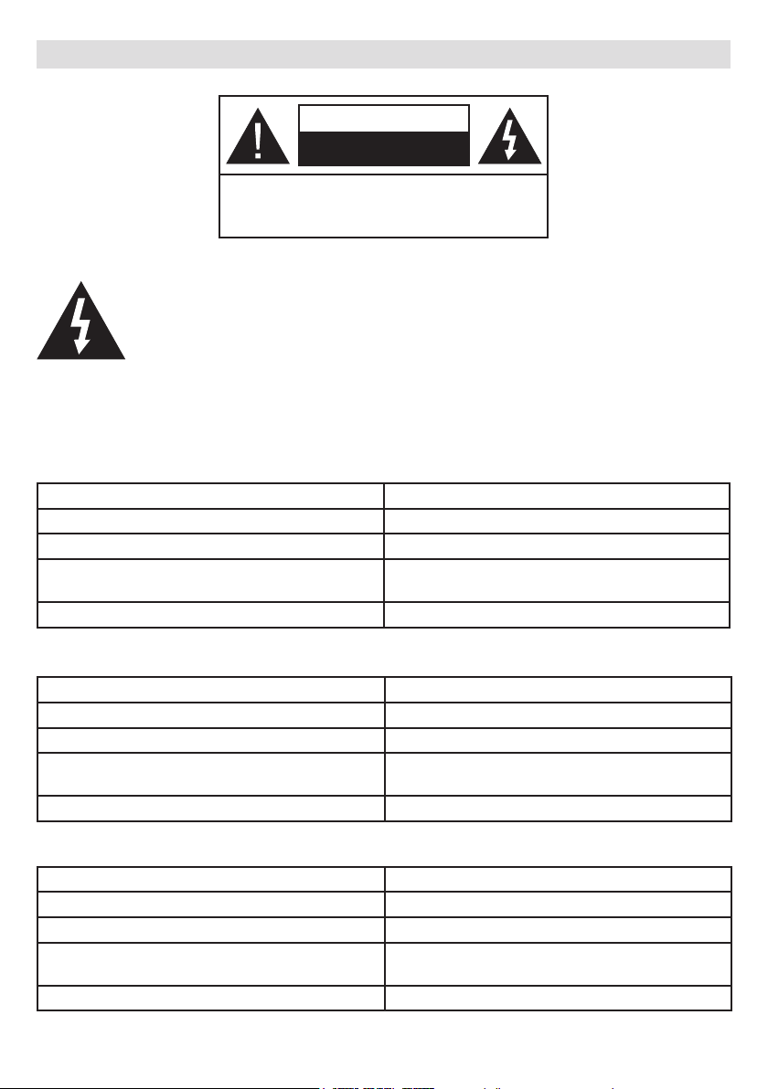
AC22 Series
Electrical Infrastructure Requirement 400VAC 50/60 Hz - 3-phase 32A
Required Circuit Breaker on AC Mains 4P-40A MCB Type-C
Required Ground Fault Protector on AC Mains 40A - 30mA RCCB Type-B
Required AC Mains Cable
5 x 6mm² (< 50m)
Outer Dimension: Ø 15-21 mm
Vehicle charge cable Type 2 socket compatible on charging station side
AC11 Series
Electrical Infrastructure Requirement 400VAC 50/60 Hz - 3-phase 16A
Required Circuit Breaker on AC Mains 4P-20A MCB Type-C
Required Ground Fault Protector on AC Mains 20A - 30mA RCCB Type-B
Required AC Mains Cable
Vehicle charge cable Type 2 socket compatible on charging station side
5 x 4mm² (< 50m)
Outer Dimension: Ø 15-21 mm
AC7 Series
Electrical Infrastructure Requirement 230VAC 50/60 Hz - 1-phase 32A
Required Circuit Breaker on AC Mains 2P-40A MCB Type-C
Required Ground Fault Protector on AC Mains 40A - 30mA RCCB Type-A
Required AC Mains Cable
Vehicle charge cable Type 2 socket compatible on charging station side
3 x 6mm² (< 50m)
Outer Dimension: Ø 12-18 mm
English - 1 -
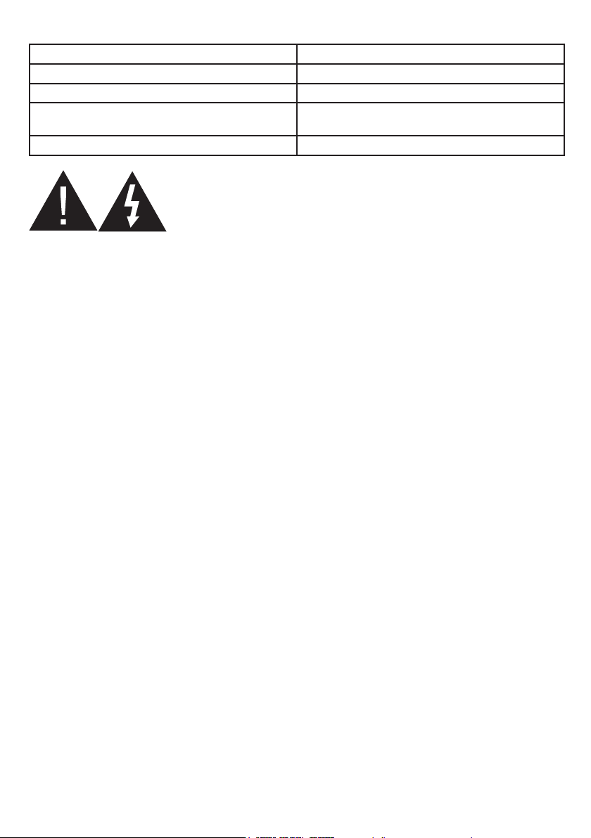
AC3 Series
Electrical Infrastructure Requirement 230VAC 50/60 Hz - 1-phase 16A
Required Circuit Breaker on AC Mains 2P-20A MCB Type-C
Required Ground Fault Protector on AC Mains 20A - 30mA RCCB Type-A
Required AC Mains Cable
Vehicle charge cable Type 2 socket compatible on charging station side
WALL MOUNTING WARNINGS
1) Read the instructions before mounting your charging station on the wall.
2) Do not install the charging station on a ceiling or inclined wall.
3) Do not install the charging station near heating devices.
4) Use the specified wall mounting screws and other accessories.
5) This unit is rated for indoor or outdoor installation.
6) If this unit is mounted outdoors, the hardware for connecting the conduits to the unit must be rated for
outdoor installation and be installed properly to maintain the proper IP rating on the unit.
3 x 4mm² (< 50m)
Outer Dimension: Ø 12-18 mm
Required Tools for Installation
•(1x) Drilling Machine
•(1x) Drill bit Ø8mm
•(1x) Hammer (for Screw Anchor)
•(1x) Torx T25 ( Security ) Screwdriver
•(1x) Torx T20 Screwdriver
•(1x) Phillips PH2/PH3 Screwdriver
•(1x) Flat(Slot type) Screwdriver
•(1x) Spirit Level (Water level)
•(1x) Wire Cutters
•(1x) Mains Tester Screwdriver
English - 2 -
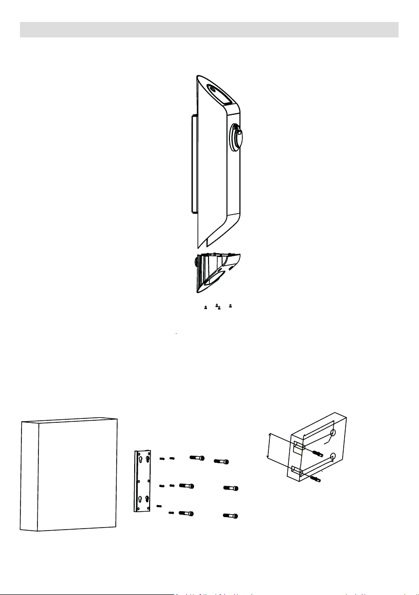
INSTALLATION STEPS
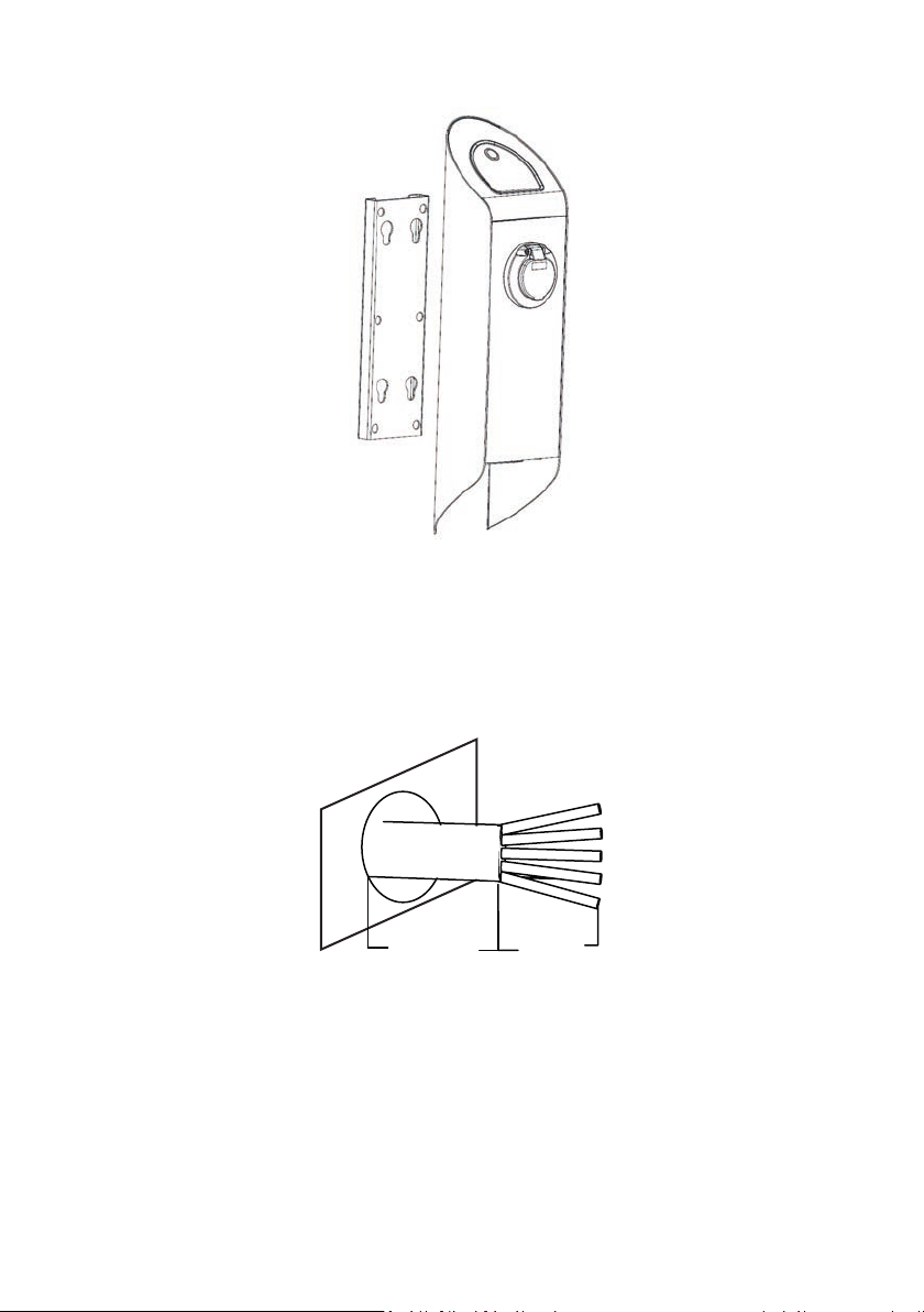
1- Remove the bottom cover and wall bracket as shown in figure below.
M5*15 SCREW-T25 Tightening Torque: 4 Nm ± 0,5 Nm
Figure 1
2- Mount the wall bracket on the wall as shown in figure below.
M6*75 SECURITY SCREW-T25 Tightening Torque: 8 Nm ± 1 Nm
Figure 2
English - 3 -
85
165
Ø7
55
33
DRAWING OF SCREW ANCHOR HOLES
3- Assemble the charger unit on wall bracket as shown in Figure below.
Figure 3
4- Prepare the AC mains cable as shown below. (for back AC inlet models)
For AC down side inlet models prepare AC inlet cable according to the cable routing in the assembly location.
150mm
Figure 4
English - 4 -
150mm
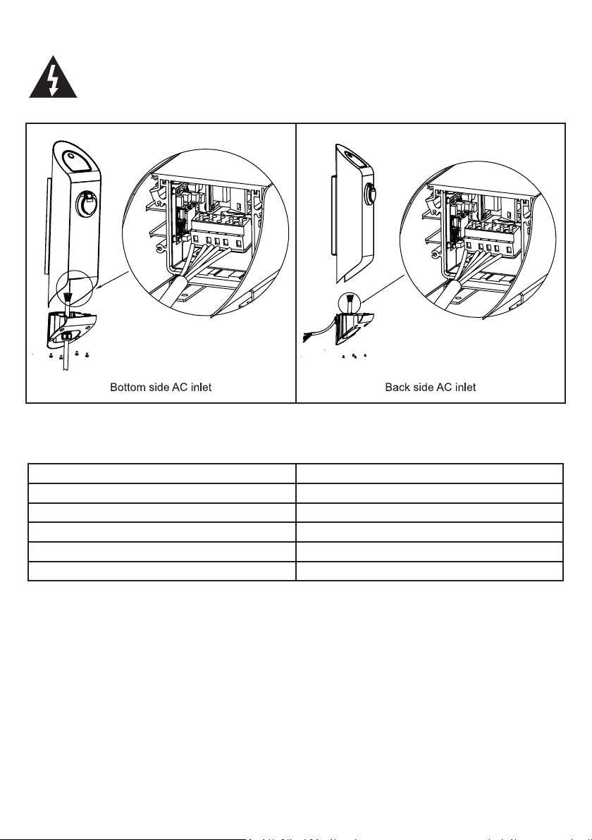
5- Connect AC Cable to Electric connector as shown in Figure below. (3-phase models)
AC mains L1, L2, L3, Neutral and Earth cables must be connected according to Table 2.
1
2
3
4
5
Figure 5
Table.2
Electric Terminal AC Cable Color
1 Earth (Green-Yellow)
2 AC L1 (Brown)
3 AC L2 (Black)
4 AC L3 (White)
5 AC Neutral (Blue)
1
2
3
4
5
English - 5 -
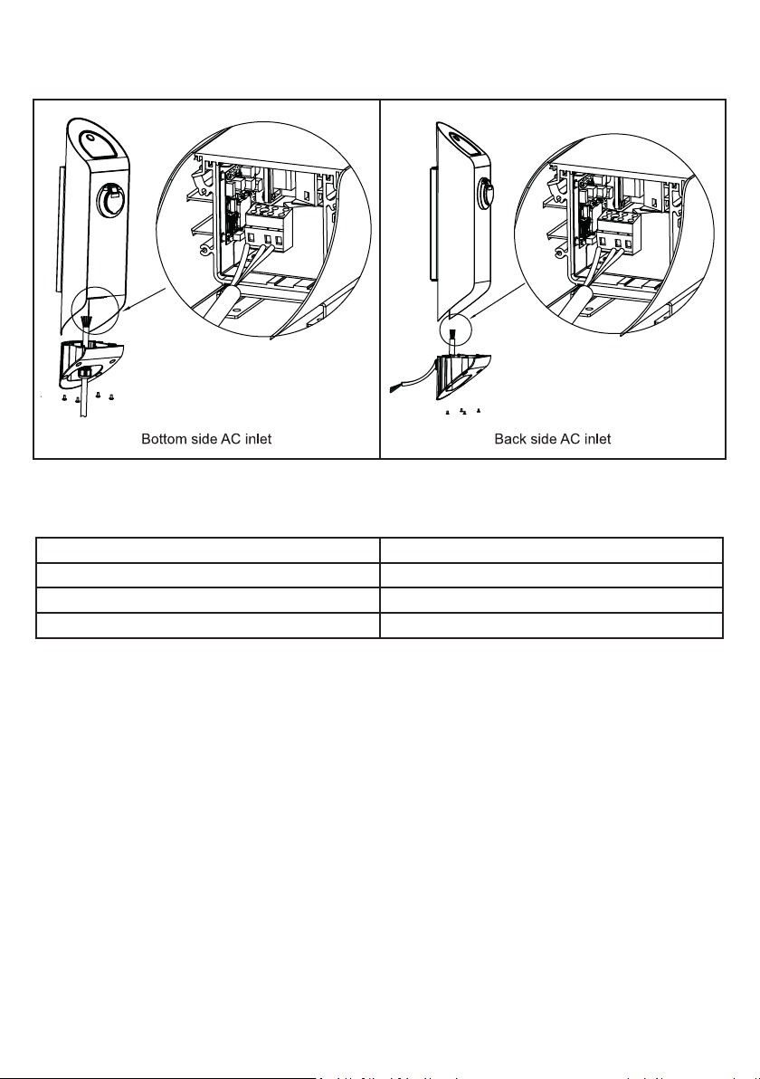
6- Connect AC Cable to Electric connector as shown in figure below.(1-phase model)
1
2
3
Figure.6
Table.3
Electric Terminal AC Cable Color
1 Earth (Green-Yellow)
2 AC Line
3 AC Neutral (Blue)
1
2
3
English - 6 -
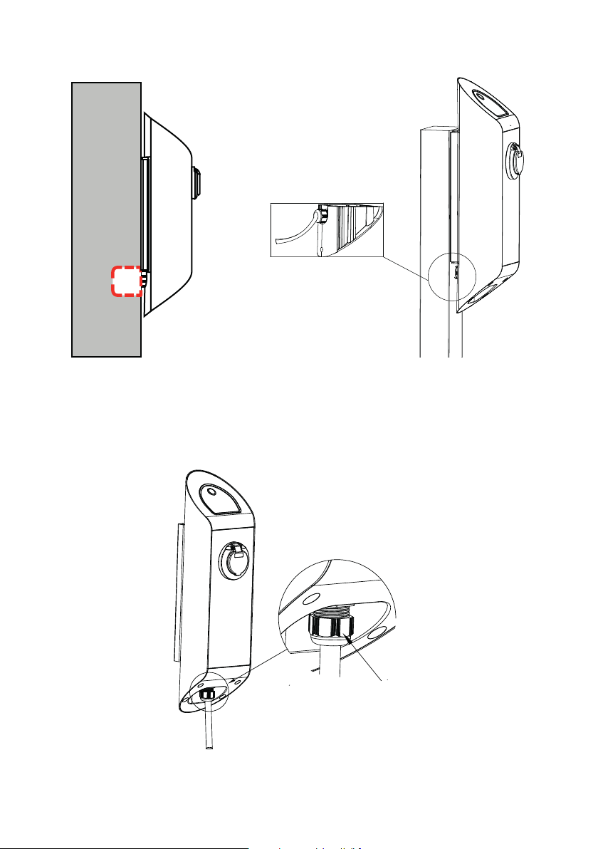
7- After mounting the bottom cover, fix the gland nut for holding the cable as shown in Figure 7.
CABLE GLAND NUT Tightening Torque: 5 Nm ± 0,5 Nm
Wall
GLAND NUT
Flush
Mounted
Socket
Figure 7
8- Also for back AC inlet models;
After mounting the bottom cover, fix the gland nut for holding the cable as shown in figure below CABLE
GLAND NUT Tightening Torque: 5 Nm ± 0,5 Nm.
Figure 8
English - 7 -
Gland Nut
 Loading...