

VES POLO100, POLO100/AT, POLO100/PC, POLO150/PC, POLO150/HM/AT Installation, Operation & Maintenance Manual
...Page 1
IMPORTANT
Before attempting to carry out any work on our units, all accompanying
documentation including warning labels on the unit must be referenced.
Should it be necessary to remove any component ensure that these are
secured into position once reinstalled. It is critical that after any
maintenance work has been conducted that all components removed
/replaced be refitted correctly by a competent engineer.
POLO100/150
Bathroom Extract Fans
VES Andover Ltd Eagle Close Chandlers Ford Ind. Est Eastleigh Hampshire SO53 4NF
Tel: 08448 15 60 60 Fax: 02380 261204 e-mail: vesltd@ves.co.uk web: www.ves.co.uk
Original Instructions : Installation, Operation & Maintenance Manual
ID Ref 846C 08/14
Original Instructions : Installation, Operation & Maintenance Manual Original Instructions : Installation, Operation & Maintenance Manual
This manual must be read in full before Installation, Operation and
Maintenance of the units supplied. Please ensure that this document is
passed to the end user. This manual forms an integral part of the product
and should be kept for the working life of the product. Additional copies of
this and supporting documents are available by contacting VES or by
visiting www.ves.co.uk and following the 'Download O & M's' link.
IMPORTANT
The following symbols used within this document refer to potential dangers
or advice for safe operation
Indicates hazards associated with electric current and high
voltages
Indicates hazards that require safety advice for personnel
and/or potential unit/property damage
Indicates important information
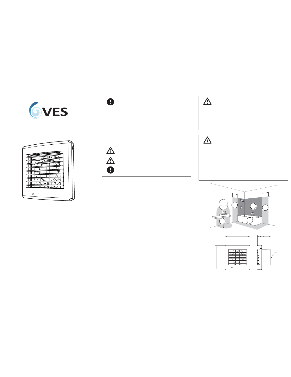
POLO fans are suitable for installation in Zone 2 and outside the zoning area
(see below)
.
IMPORTANT
EXCEPT all HM/AT & AS/HM/AT models which MUST be
mounted outside the zoning area
All POLO fans must be sited and installed in accordance with current IEE
Regulations BS7671 and the appropriate Building Regulations.
POLO fans are suitable for wall or ceiling
mounting except the PC (pull cord) model which is suitable for wall
mounting only.
The fan should be installed in conjunction with an appropriate mounting kit
and consideration must be given to ensure that access to all moving parts of
the fan are restricted when the fan is in use.
Unit Description
The POLO series is range of axial fans suitable for bathroom extract
applications; for full unit details please see the unit specification later in the
document.
Immediately upon receipt of your POLO fan, check there is no damage to
the fan, and that the four fixing screws and matching wall plugs are
included within the ancillary bag.
In the event of any damage having occurred or if any item is found to be
missing, it is essential to inform VES Andover Ltd. within 7 days of delivery
quoting sales order number and the unit type. After this period, VES would
be unable to accept any claim for damaged or missing goods.
Part Number Description
POLO100 or 150 ............................ Standard extract fan
POLO100 or 150/PC .......................Fan c/w pull chord
POLO100 or 150/AT ....................... Fan c/w adjustable timer
POLO100 or 150/HM/AT.................Fan c/w adjustable humidistat & timer
POLO100 or 150/PIR/AT..................Fan c/w PIR sensor & timer
POLO100 or 150/AS .......................Fan c/w automatic shutter
POLO100 or 150/AS/AT ..................Fan c/w auto shutter &timer
POLO100 or 150/AS/HM/AT............Fan c/w auto shutter, humidistat & timer
POLO100 or 150/AS/PIR/AT............ Fan c/w auto shutter, PIR sensor & timer
Dimensions AB C DØ(mm)
POLO100 156 154 29 55 98
POLO150 209 208 31 69 148
A
B
C
D
Ø
1
zone
0
zone
2
zone
2
zone
2
zone
600mm
600mm
600mm
2250mm
Page 2
IMPORTANT
Before a
to carry out any maintenance or repair work on our
units, the unit MU
ST BE COMPLETELY ISOLATED from its electrical supply.
Ensur
e a minimum of two minutes a er electrical disc efore
a
ow any moving parts to come to a rest.
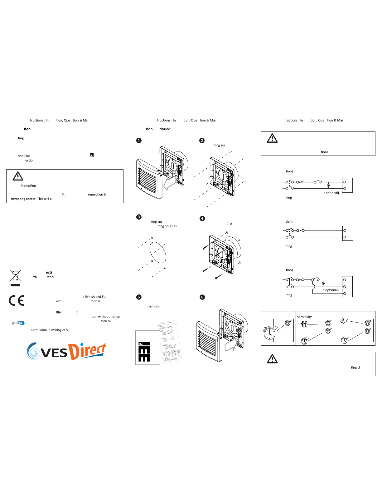
Fan
Terminals
Mark centre holes on
moun
face then
drill out
Remove cover from
POLO fan
VES Andover Ltd Eagle Close Chandlers Ford Ind. Est Eastleigh Hampshire SO53 4NF
Tel: 08448 15 60 60 Fax: 02380 261204 e-mail: vesltd@ves.co.uk web: www.ves.co.uk
Original Ins stalla ra ntenance Manual Original Ins stalla ra ntenan ce ManualOriginal Ins stalla ra ntenance Manual
WEEE Dir
ve
A
e endo
r usefullife the packagingand product should
be disposedof via asuitable recycling centre. Donot dispose of
with normalhousehold waste. Do notburn.
Standards
All POLO fans conform to all relevan
ropean
standards and dir
ves. Further informa
available
from VES Andover Ltd on request
Please ensure tha
s documen s passed on to theend user
We reserve the right to alter the specifica
©VES Andover Ltd. 2009. No part of this publica
ay be
photocopied or otherwise reproduced without the prior
ES Andover Ltd.
Wire the fan as per
wiring diagram &
ins
Prepare hole in
moun
face &
plug moun
required
Replace front cover
Installa con
Wiring Diagrams
Secure fan backing
plate to moun
surface
Standard, /AS
(Typical Installa
/PC, /PIR/AT, /AS/PIR/AT
(Typical Installa
/AT, /HM/AT, /AS/AT, /AS/HM/AT
(Typical Installa
Maintenance
1. Before cleaning, isolate the fan completely from the mains supply.
2. Carefully remove the front cover
3. T
o clean the front cover, either wipe it with a damp, lint free cloth or
wash it in warm soapy water. Thoroughly dry the front cover and refit.
4. Do not immerse the fan in water or other liquids to clean any other parts
of the fan.
5. Never use strong solvents to clean the fan.
6. Apart from cleaning, no other maintenance is required.
For replacement fans or install kits please visit www.vesdirect.co.uk
Specifica
Power Supply 230V 50Hz
Opera
Temperature 0~40°C
Insula
s Double insulated
Motor Prot
n IPX4
gniraeb llaBepyT rotoM
0562)mpr( deepS
Power (W) (POLO100/150) 15/25
Current (A) (POLO100/150) 0.1/0.15
(HM/AT & AS/HM/AT IPX2 only)
+-
AT model
2-23
mins
run-on
-
+
-
+
-
+
Movement
2-23 mins
run-on
PIR model
- +
+-
PCB
BCPBCP
- +
+-
HM model
Humidistat
+
-
+
-
2-23 mins
run-on
IMPORTANT
The fan must be fused at 3A unless it forms part of a 5A ligh
rcuit.
An isolator should be installed to isolate all poles to the fan.
IMPORTANT
All electrical work should be carried out by a qualified engineer and in
accordance with the current IEE Regula
Warranty
The fan is guaranteed against defects for 1 year from the date of purchase.
If you have any problems, contact VES at the address shown below.
Fan
Terminals
(Ligh
(Ligh
Fuse
Fuse
Fuse
Remote/
Light Switch
Remote/
Light Switch
Double Pole
Isola
Switch
Double Pole
Isola
Switch
Double Pole
Isola
Switch
L
L
L
L
T
L
L
N
N
N
N
N
N
Fan
Terminals
 Loading...