

Page 1
Operating Instructions & Parts Manual
IMPORTANT: READ AND SAVE THESE INSTRUCTIONS. Read carefully before attempting to assemble, install, operate or maintain the
product described. Protect yourself and others by observing all safety information. Failure to comply with instructions could result in
personal injury and/or property damage! Retain instructions for future reference.
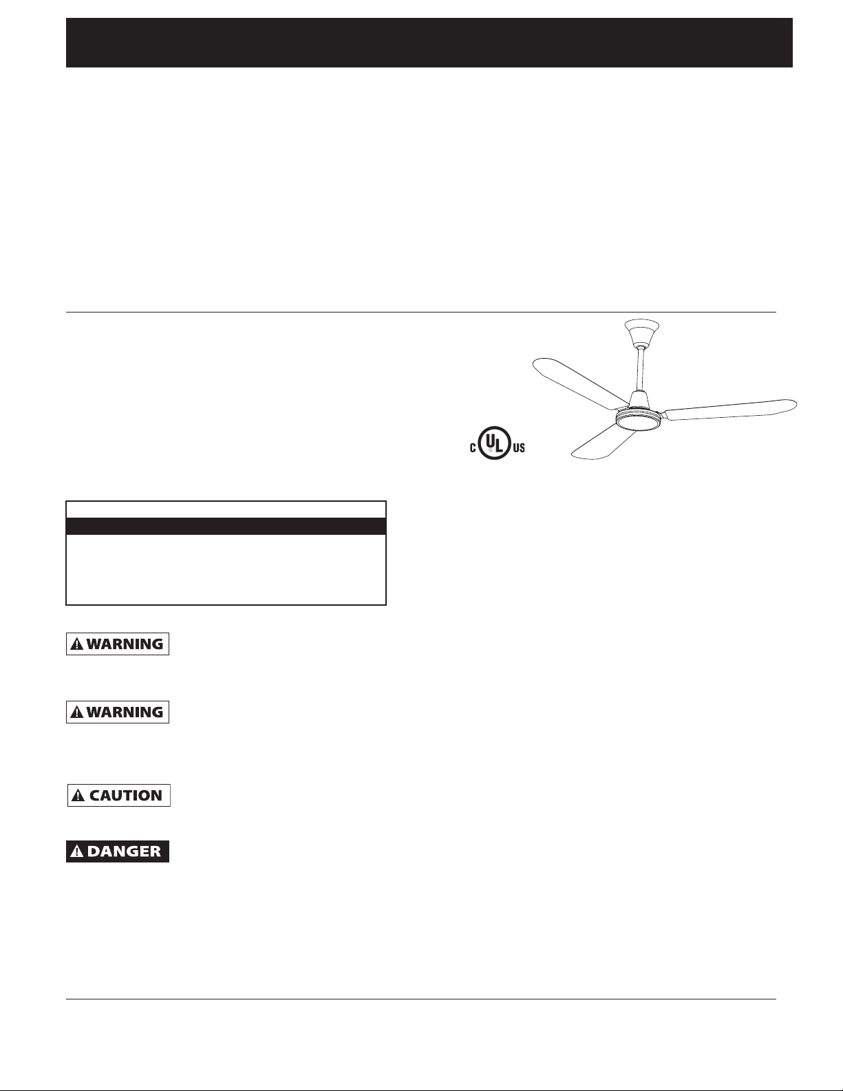
Commercial Ceiling
Fans
Description
The VES commercial ceiling fans are a high efficiency, commercial ceiling fan. It
is designed to create air velocity and a cooling effect on high speed. The lower
speeds can be used for reduced velocity or heat de-stratification. The low speed
gently de-stratifies the air giving a constant room temperature. Models are UL &
cUL Certified.
Unpacking
1. After opening carton, look for concealed damage.
2. If concealed damage is found, immediately file claim with carrier.
Specifications
Model Size Volts Hertz Amps Watts RPM
INDA364L 36˝ 120 60 0.35 40 360
INDA484L 48˝ 120 60 0.50 50 320
INDA564L 56˝ 120 60 0.55 65 280
INDA56P 56˝ 120 60 0.55 65 280
General Safety Information
Disconnect power
supply before wiring
connections are made to prevent possible
electric shock or damage to equipment.
Read and follow
instructions carefully.
Failure to comply with instructions could
result in fire, electric shock, injury to
persons and/or damage to equipment.
Follow all
maintenance
procedures enclosed.
Failure to properly
ground unit could
result in severe electrical shock or death.
1. All wiring should conform to the
National Electrical Code ANSI/NFPA
70-1999 (NEC) in the United States,
CEC and local regulations.
2. Do not mount in an area which will
allow the ceiling fan to come in
contact with moisture.
3. Make certain the entire installation
is grounded as a precaution against
possible electrical shock.
4. Do not exceed maximum
amperage rating of the ceiling fan
as overloading can result in
damage to ceiling fan and control.
5. When wiring an electrical
appliance or device follow all electrical and safety codes, as well as
the most recent NEC, CEC and local
regulations and the Occupational
Safety and Health Act (OSHA).
6. Suitable for use with a VES solid
state speed control.
E249273
Assembly
1. Remove all ceiling fan parts from
the box.
2. Tools and supplies needed – Flat and
Phillips screwdriver – 9/16” and 3/8”
open wrench or adjustable wrench,
2-3 wire nuts.
3. Install a junction box to accept the
wiring of the fan. In many cases, a
qualified electrician will be required
to install the outlet box keeping
with local electrical codes or to
meet the NEC, CEC and local
regulations.
4. For installation to open web steel
joist – use threaded J-hook as
supplied. For wood joist
construction – use J-hook with lag
threads (not supplied. For attachment in concrete, drill concrete
anchors into the concretes as per
specification applicable to NEC, CEC
and local regulations.
Form IS1100
Version 1
01/2017
VES001
01/2017
624
Page 2
Operating Instructions & Parts Manual
Commercial Ceiling Fans
2
8
1
4
17
6
7
5
Figure #1
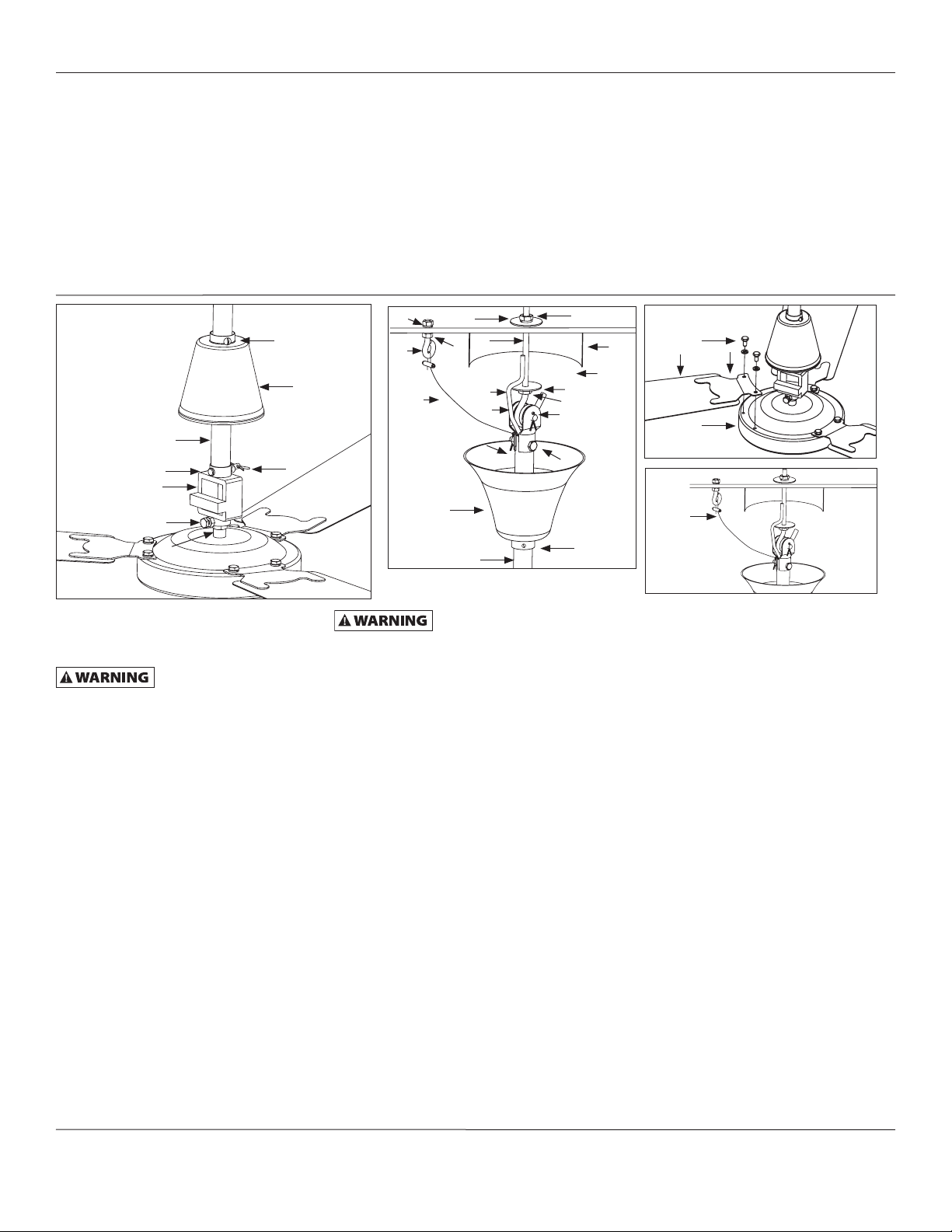
Installation
Safety Product Inspection of Fan Prior to
Installation (Figure #1 and #2)
To reduce the risk of
personal injury, do not
bend the blade brackets when installing the
brackets, balancing the blades or cleaning
the fan. Do not insert foreign objects in
between rotating fan blades.
1. Make certain set screw (4) is tight to
ascertain wobble free operation.
2. Make certain cotter pin (5) is in place
and secure.
3. Make certain lock-nut (7) is tight and
set screw (6) is in place and secure.
4. Slide lower canopy (8) down over
rubber gasket (21) to create a tight
seal.
5. Make certain lower canopy set
screws (2) are tight on downrod (1).
6. Make certain cotter pin (13) is in
place and secure.
7. Make certain bolt, cotter pin and nut
(16) are tight.
Hanging of Fan (Figure #1 and #2)
. Wind one nut (9) down to bottom of
J hook (12) towards the curve. Add a
lock washer and then flat washer (3)
on top of the nut (9).
30
31
11
Figure #2
Figure #4). Make certain safety cable is
attached properly to hook or structural
member. Failure to comply with instructions could result in personal injury and/
or property damage.
20
12
29
10
14
16
19
1
Make certain crimp on
safety loop is secure (See
22
3
9
13
15
18
2. Drill a 5/32” pilot hole for safety
hook (31) within a 12” radius of J
hook (12) support for fan. Wind one
nut down (29) to bottom of safety
hook towards the loop. Add a lock
washer (29) and slide safety hook
through pilot hole. Slide lock washer
(30)on top side of the safety hook
and add nut (30). Tighten so lock
washer on top and bottom of the
structure are secure.
3. Drill a 1/2” pilot hole for J hook. Put
J hook (12) through pilot hole in
joist. Add flat washer and then lock
washer (20) and nut (22). Do not
tighten completely until fan is put in
place on J hook. A lubricant should
not be used on the single mounting screw; and the pilot hole should
be drilled no larger than the minor
diameter of the mounting screw
threads, and at least 38 mm (1-1/2”)
28
27
23
25
26
24
Figure #3
11
Safety
Cable
Figure #4
of the threaded part of the mounting screw should be secured into
a structural joist to provide secure
mounting.
4. Loosen set screw (18) on top canopy
(19) on fan downrod (1) and lower
the canopy to make room to place
rubber grommet (14) onto
mounting hook.
5. Tighten top nut (22) on J hook to
raise fan into proper installation
position.
6. Ensure power to outlet box is off before hooking up wiring (10) (except
INDA56P see note below). Wire the
fan according to NEC, CEC and local
electrical codes (see Figure #5 or 6).
After making the wire connections
as outlined in Figure #5 or 6, the
wires should be spread apart with
the grounded conductor and the
equipment-grounding conductor on
one side of the outlet box and the
ungrounded conductor on the other
side of the outlet box. Splices should
be turned upward and pushed carefully up into the outlet box.
2
Page 3
Operating Instructions & Parts Manual
CEILING
FAN
Commercial Ceiling Fans
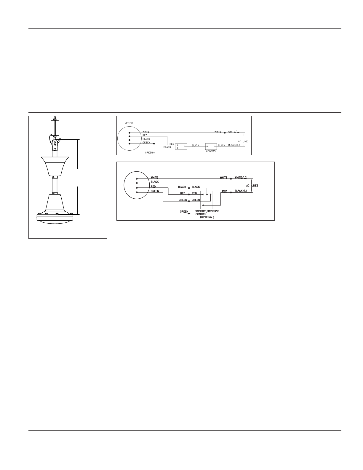
Figure #5 - Wiring diagram for Forward/
Top of Rubber
Grommet
18”
Reverse.
120V
Optional F/R Switch
Figure #6 - Wiring diagram for optional #ICFCFR5 control.
Flat surface
blades attach.
Length of downrod is
measured as shown above.
Note: Model INDA56P already has a 3
prong plug wired for 120V. Cord
must be plugged into a properly
wired 120V grounded outlet.
7. Raise top canopy (19) up the
downrod to cover hook. Leave 1/8”
gap between top canopy (19) and
hanging surface (so downrod does
not move off center which could
make fan wobble or vibrate and
transmit motor noise to ceiling
surface). Tighten set screw (18).
8. Attach blades (23) to motor (24)
with blade bolts (25). (Figure #3)
The blade (24) should be positioned
below the blade arm bracket (26)
when attaching to the motor to get
proper air flow and direction.
ICFCFR5
IMPORTANT:
The standard downrod installed properly
be mounted a minimum 10’ above the floor
level. It is critical that the “J” hook and nut
adjustment is done so that the blades will
be a minimum 12” from the ceiling. If your
ceiling is less that 12’ than the hook and
downrod must be recessed into the ceiling
so that the blades are mounted 10’ above
the floor level to meet OSHA standards.
Operation
For optimum fan performance, use the
VES model ICFCFR5 control to adjust
speed and direction of your fan (see
figure #6 for wiring). Follow the instructions included with the control for
minimum speed setting and operation.
The forward/reverse control will allow
you to adjust the speed and direction of
the fan. The forward/downdraft direction blows air down on high speed for
cooling or low speed for heat de-stratification. The reverse direction is idle
for heat de-stratification or creating air
movement without direct air flow.
3
Page 4

Operating Instructions & Parts Manual
Maintenance
Always disconnect the
power supply before
servicing the ceiling fan or
working with the unit for any reason.
Parts replacement and
troubleshooting to be
performed only by qualified personnel.
Do not place fingers or
objects in the ceiling
fan while motor is connected to the power
source.
Do not attach foreign
objects to the blades of
the ceiling fan.
Do not use gasoline,
benzene, thinner, harsh
cleaners, etc., which are dangerous and will
damage the ceiling fan.
If you see noticeable
vibration, wobbling or
wear the fan should be removed from service
and repaired or replaced by a qualified
maintenance technician or electrician.
• Below is the maintenance schedule
that must be followed and filled out
to be eligible for warranty and ensure
safe operation.
• Inspection should be every 3500
running hours or every 6 months.
• Maintenance schedule should include
repeating the product inspection
procedure and the fan hanging
procedure.
Initial Installation Date : ______________________ Name of installation supervisor : ______________________________
Maintenance Schedule
Maintenance Estimated Approved S - Scheduled Work Performed/
Date Running Hours Inspector Name: U - Unscheduled Notes/Comments
______________________________________________________________________________________
______________________________________________________________________________________
______________________________________________________________________________________
______________________________________________________________________________________
______________________________________________________________________________________
______________________________________________________________________________________
______________________________________________________________________________________
______________________________________________________________________________________
______________________________________________________________________________________
______________________________________________________________________________________
______________________________________________________________________________________
______________________________________________________________________________________
______________________________________________________________________________________
______________________________________________________________________________________
______________________________________________________________________________________
______________________________________________________________________________________
______________________________________________________________________________________
______________________________________________________________________________________
______________________________________________________________________________________
______________________________________________________________________________________
______________________________________________________________________________________
______________________________________________________________________________________
4
Page 5

Operating Instructions & Parts Manual
For Repair Parts, call 1-888-622-2999
Please provide following information:
- Model number
- Serial number (if any)
- Part description and number as shown in parts list
3
1
5
Replacement Part List
Ref. # Description
1 18” downrod w/rubber support
2 Lower canopy
3 Support hook
4 Upper canopy
5 Blade set curved (3 blades per set)
6 Capacitor
7 Motor housing with yoke
4
2
6
7
5
Page 6

Operating Instructions & Parts Manual
Troubleshooting Chart
Commercial Ceiling Fan is tested before it leaves the factory, resulting in an extremely low rate of returns. However, due to shipping and installation
procedures, occasionally a fan will need a minor adjustment to run satisfactorily.
If this should happen, we recommend that you identify the problem and try the
simple suggestions listed below.
Turn off power at main circuit breaker before checking!
Symptom Corrective Action
Fan will not start a) Check fuses and circuit breakers.
b) Check wire connections to fan.
c) Check wiring connection in lower canopy.
d) Check voltage at fan connection.
__________________________________________________________________________________________________________________
Fan too fast / slow a) Adjust the trim set screw in fan wall control if using optional wall control. If minimum
setting is too low the fan may shut off with voltage fluctuations. Increase minimum.
b) Check voltage at fan connection.
c) Blades must be attached to motor to reduce the speed.
__________________________________________________________________________________________________________________
Fan makes noise a) Check motor case to make certain all visible screws are snug.
b) Check to make certain that all blade bracket screws are tight.
c) Check for labels or wire nuts that could be rubbing.
d) All ceiling fans may have a slight motor noise known as the “60 cycle hum” when used
with solid state infinite speed controls. Especially on lower speeds. This hum will not
affect the fan performance.
e) Make certain upper canopy is at least 1/8” from ceiling
f) Allow a 30 days break-in period which normally eliminates any Residual noise other
than a), b), c), d) or e).
__________________________________________________________________________________________________________________
Fan wobbles a) Check that all blade brackets are screwed firmly to motor case.
b) Check distance from tip of blades to ceiling. If blades get bent during installation, you
must re-adjust them so that all blades travel on same plane. Gently bend up or down
until all distancea are the same.
c) Make certain upper canopy is 1/8” from ceiling.
d) Make certain that hanging hooks are secured tightly to ceiling.
e) Run fan without blade, if motor does not wobble, then motor is not defective but the
blades maybe bent.
6
Page 7

Operating Instructions & Parts Manual
LIMITED WARRANTY
VES ONE-YEAR LIMITED WARRANTY. MODELS COVERED IN THIS MANUAL, ARE WARRANTED BY VES ENVIRONMENTAL
SOLUTIONS, LLC. (VES) TO THE ORIGINAL USER AGAINST DEFECTS IN WORKMANSHIP OR MATERIALS UNDER NORMAL USE
FOR ONE YEAR AFTER DATE OF PURCHASE. ANY PART WHICH IS DETERMINED TO BE DEFECTIVE IN MATERIAL OR WORKMANSHIP AND RETURNED TO AN AUTHORIZED SERVICE LOCATION, AS VES DESIGNATES, SHIPPING COSTS PREPAID, WILL
BE, AS THE EXCLUSIVE REMEDY, REPAIRED OR REPLACED AT VES’S OPTION. FOR LIMITED WARRANTY CLAIM PROCEDURES,
SEE “PROMPT DISPOSITION” BELOW. THIS LIMITED WARRANTY GIVES PURCHASERS SPECIFIC LEGAL RIGHTS WHICH VARY
FROM JURISDICTION TO JURISDICTION.
LIMITATION OF LIABILITY. TO THE EXTENT ALLOWABLE UNDER APPLICABLE LAW, VES’S LIABILITY FOR
CONSEQUENTIAL AND INCIDENTAL DAMAGES IS EXPRESSLY DISCLAIMED. VES’S LIABILITY IN ALL EVENTS IS
LIMITED TO AND SHALL NOT EXCEED THE PURCHASE PRICE PAID.
WARRANTY DISCLAIMER. A DILIGENT EFFORT HAS BEEN MADE TO PROVIDE PRODUCT INFORMATION AND ILLUSTRATE
THE PRODUCTS IN THIS LITERATURE ACCURATELY; HOWEVER, SUCH INFORMATION AND ILLUSTRATIONS ARE FOR THE
SOLE PURPOSE OF IDENTIFICATION, AND DO NOT EXPRESS OR IMPLY A WARRANTY THAT THE PRODUCTS ARE
MERCHANTABLE, OR FIT FOR A PARTICULAR PURPOSE, OR THAT THE PRODUCTS WILL NECESSARILY CONFORM TO THE
ILLUSTRATIONS OR DESCRIPTIONS. EXCEPT AS PROVIDED BELOW, NO WARRANTY OR AFFIRMATION OF FACT, EXPRESSED
OR IMPLIED, OTHER THAN AS STATED IN THE “LIMITED WARRANTY” ABOVE IS MADE OR AUTHORIZED BY VES.
Technical Advice and Recommendations, Disclaimer. Notwithstanding any past practice or dealings or trade custom,
sales shall not include the furnishing of technical advice or assistance or system design. VES assumes no obligations or
liability on account of any unauthorized recommendations, opinions or advice as to the choice, installation or use of
products.
Product Suitability. Many jurisdictions have codes and regulations governing sales, construction, installation, and/or use of
products for certain purposes, which may vary from those in neighboring areas. While attempts are made to ascertain that
VES products comply with such codes, VES cannot guarantee compliance, and cannot be responsible for how the
product is installed or used. Before purchase and use of a product, review the product applications, and all applicable
national and local codes and regulations, and be certain that the product, installation, and use will comply with them.
Certain aspects of disclaimers are not applicable to consumer products; e.g., (a) some jurisdictions do not allow the
exclusion or limitation of incidental or consequential damages, so the above limitation or exclusion may not apply to you;
(b) also, some jurisdictions do not allow a limitation on how long an implied warranty lasts, consequently the above
limitation may not apply to you; and (c) by law, during the period of this Limited Warranty, any implied warranties of
implied merchantability or fitness for a particular purpose applicable to consumer products purchased by consumers, may
not be excluded or otherwise disclaimed.
Prompt Disposition. A good faith effort will be made for prompt correction or other adjustment with respect to any
product which proves to be defective within limited warranty. For any product believed to be defective within limited
warranty, first write or call dealer from whom the product was purchased. Dealer will give additional directions. If unable
to resolve satisfactorily, write to VES at address below, giving dealer’s name, address, date, and number of dealer’s
invoice, and describing the nature of the defect. Title and risk of loss pass to buyer on delivery to common carrier.
If product was damaged in transit to you, file claim with carrier.
Manufactured for VES Environmental Solutions, LLC. 8296 Commerce Pkwy, Ste 2, Chippewa Falls, WI 54729 USA U.S.A.
7
 Loading...