

Vertiv NetSure Series, NetSure R48-4000e, NetSure R48-3500e, NetSure R48-3200e, NetSure R48-3200 User Manual
Page 1

NetSure™
Rectifier Module
User Manual (UM1R483500e), Revision R
Specification Number: 1R484000e, 1R483500e, 1R483200e, 1R483200
Model Number: R48-4000e, R48-3500e, R48-3200e, R48-3200
Page 2

2
The information contained in this document is subject to change without
notice and may not be suitable for all applications. While every precaution
has been taken to ensure the accuracy and completeness of this
document, Vertiv Group Corporation assumes no responsibility and
disclaims all liability for damages resulting from use of this information or
for any errors or omissions. Refer to other local practices or building codes
as applicable for the correct methods, tools, and materials to be used in
performing procedures not specifically described in this document.
This document may contain confidential and/or proprietary information of
Vertiv Group Corporation, and its receipt or possession does not convey
any right to reproduce, disclose its contents, or to manufacture or sell
anything that it may describe. Reproduction, disclosure, or use without
specific authorization from Vertiv Group Corporation is strictly prohibited.
Vertiv and the Vertiv logo are trademarks or registered trademarks of
Vertiv Co. All other names and logos referred to are trade names,
trademarks or registered trademarks of their respective owners.
© 2018 Vertiv Co. All rights reserved.
Vertiv | NetSure Rectifier Module User Manual (UM1R483500e) | Rev. R
Page 3

3
TABLE OF CONTENTS
Admonishments Used in this Document ............................................................ 4
Important Safety Instructions .............................................................................. 5
General Safety ...........................................................................................................................................................5
Voltages ...........................................................................................................................................................................5
AC Input Voltages ........................................................................................................................................................ 5
DC Output and Battery Voltages .................................................................................................................. 5
Hazardous Voltage ...............................................................................................................................................5
Handling Equipment Containing Static Sensitive Components..............................5
Static Warning ........................................................................................................... 6
Introduction ............................................................................................................... 7
Overview .......................................................................................................................................................................... 7
Specifications ............................................................................................................................................................. 7
DC Output Ratings ...................................................................................................................................................... 7
AC Input Ratings ......................................................................................................................................................... 13
Environmental Ratings ..........................................................................................................................................18
Compliance Information: ..................................................................................................................................... 19
Standard Features .................................................................................................................................................... 19
Mechanical Specifications ................................................................................................................................. 22
Operation ..................................................................................................................23
AC Input Protection Device Requirements/Recommendations.......................... 23
Local Indicators .................................................................................................................................................... 23
Rectifier High Voltage Shutdown and Lockout Restart .............................................. 24
Installing Rectifiers ............................................................................................................................................ 25
Troubleshooting and Repair ............................................................................... 26
Troubleshooting .................................................................................................................................................. 26
Rectifier Current Sharing Imbalance ....................................................................................................... 26
Rectifier Fault Symptoms and Troubleshooting .......................................................................... 26
Replacement Procedures ........................................................................................................................... 28
Rectifier Replacement ........................................................................................................................................... 28
Rectifier Fan Replacement ............................................................................................................................... 29
Vertiv | NetSure Rectifier Module User Manual (UM1R483500e) | Rev. R
Page 4
4
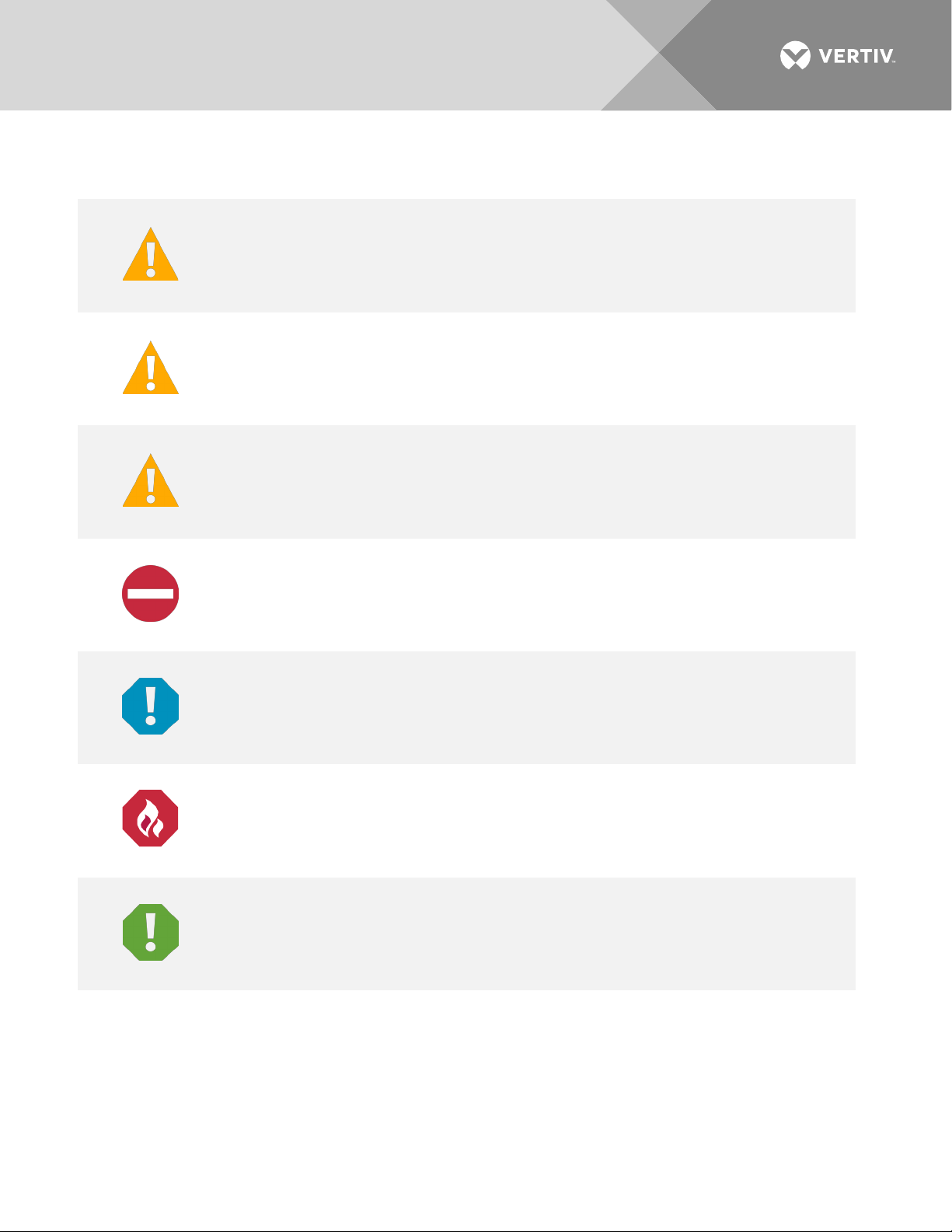
DANGER
in death or serious injury if not avoided. (ANSI, OSHA)
WARNING
result in
death or serious injury if not avoide
risk only to equipment, software, data, or service. (ANSI)
CAUTION
result in minor or moderate injury if not avoided. (ANSI, OSHA) This admonition is not
used for situations that pose a risk only to equipment, data, or service, even if such use
appears to be permitted in some of the applicable standards. (OSHA)
ALERT
equipment, software, data, or service. (ISO)
ALERT
equipment damage, software corruption, data loss, o
FIRE SAFETY
or policies, or of the locations of fire
SAFETY
policies not related to a particular source of hazard or to fire safety. (ISO, ANSI, OSHA)
ADMONISHMENTS USED IN THIS DOCUMENT
! Warns of a hazard the reader
! Warns of a potential hazard the reader
! Warns of a potential hazard the reader
! Alerts the reader to an action that
will
be exposed to that will
may
be exposed to that
d. This admonition is not used for situations that pose a
may
be exposed to that
must be avoided
in order to protect
likely
result
could
could
! Alerts the reader to an action that
! Informs the reader of fire safety information, reminders, precautions,
! Informs the reader of general safety information, reminders, precautions, or
Vertiv | NetSure Rectifier Module User Manual (UM1R483500e) | Rev. R
-fighting and fire-safety equipment. (ISO)
must be performed
r service interruption. (ISO)
in order to prevent
Page 5

5
IMPORTANT SAFETY INSTRUCTIONS
General Safety
DANGER! YOU MUST FOLLOW APPROVED SAFETY PROCEDURES.
Performing the following procedures may expose you to hazards. These procedures should be
performed by qualified technicians familiar with the hazards associated with this type of equipment.
These hazards may include shock, energy, and/or burns. To avoid these hazards:
a) The tasks should be performed in the order indicated.
b) Remove watches, rings, and other metal objects.
c) Prior to contacting any uninsulated surface or termination, use a voltmeter to verify that no voltage
or the expected voltage is present. Check for voltage with both AC and DC voltmeters prior to
making contact.
d) Wear eye protection.
e) Use certified and well maintained insulated tools. Use double insulated tools appropriately rated for
the work to be performed.
Voltages
AC Input Voltages
DANGER! This system operates from AC input voltage capable of producing fatal electrical shock.
DC Output and Battery Voltages
DANGER! This system produces DC power and may have a battery source connected to it. Although
the DC voltage is not hazardously high, the rectifiers and/or battery can deliver large amounts of current.
Exercise extreme caution not to inadvertently contact or have any tool inadvertently contact an output
terminal or battery terminal or exposed wire connected to an output terminal or battery terminal.
NEVER allow a metal object, such as a tool, to contact more than one termination or battery terminal at a
time, or to simultaneously contact a termination or battery terminal and a grounded object. Even a
momentary short circuit can cause sparking, explosion, and injury.
Hazardous Voltage
DANGER! HAZARD OF ELECTRICAL SHOCK.
More than one disconnect may be required to de-energize the system before servicing.
Handling Equipment Containing Static Sensitive Components
ALERT! Installation or removal of equipment containing static sensitive components requires careful
handling. Before handling any equipment containing static sensitive components, read and follow the
instructions contained on the Static Warning Page.
Vertiv | NetSure Rectifier Module User Manual (UM1R483500e) | Rev. R
Page 6

6
STATIC WARNING
This equipment contains static sensitive components. The warnings listed below must be observed to
prevent damage to these components. Disregarding any of these warnings may result in personal injury
or damage to the equipment.
1. Strictly adhere to the procedures provided in this document.
2. Before touching any equipment containing static sensitive components, discharge all static
electricity from yourself by wearing a wrist strap grounded through a one megohm resistor. Some
wrist straps have a built-in one megohm resistor; no external resistor is necessary. Read and follow
wrist strap manufacturer’s instructions outlining use of a specific wrist strap.
3. Do not touch traces or components on equipment containing static sensitive components. Handle
equipment containing static sensitive components only by the edges that do not have connector
pads.
4. After removing equipment containing static sensitive components, place the equipment only on
conductive or anti-static material such as conductive foam, conductive plastic, or aluminum foil. Do
not use ordinary Styrofoam™ or ordinary plastic.
5. Store and ship equipment containing static sensitive components only in static shielding containers.
6. If necessary to repair equipment containing static sensitive components, wear an appropriately
grounded wrist strap, work on a conductive surface, use a grounded soldering iron, and use
grounded test equipment.
Vertiv | NetSure Rectifier Module User Manual (UM1R483500e) | Rev. R
Page 7

7
INTRODUCTION
Overview
The rectifiers provide load power, battery float current, and battery recharge current during normal operating
conditions. The rectifiers are a constant power design. The rectifiers are rated at their maximum output power.
This means that, within the normal operating ambient temperature range and input voltage range, the
maximum available output power is a constant 4000 W, 3500 W, or 3200 W (depending on rectifier model).
Within these ranges, the rectifiers operate in one of three modes, depending upon load demands. Transition
between modes is completely automatic. If ambient temperature rises above or input voltage falls below
acceptable values, rectifiers continue to operate but at derated output power levels.
• Constant Voltage Mode: For any initial output voltage setting from 42 VDC to 58 VDC, output voltage
remains constant regardless of load. This is the normal operating condition, in which loads are being
supplied and batteries are float charged. Rectifiers operate in the Constant Voltage Mode unless load
increases to the point where the product of load current and output voltage is approximately 4000 W,
3500 W, or 3200 W (depending on rectifier model).
• Constant Power Mode: As load increases above approximately 4000 W, 3500 W, or 3200 W (depending
on rectifier model) (non-adjustable), output current continues to increase, but output voltage decreases
as required to maintain constant output power. Rectifiers operate in the Constant Power Mode unless
load continues to increase to the point where the current limit setting is reached.
• Constant Current Mode: If load increases to the current limit setting, output voltage decreases linearly
to maintain output current at the current limit setting.
Specifications
DC Output Ratings
NOTE!
controller.
• Voltage: Nominal -48.0 VDC, Positive Ground.
a) Adjustment Range: The output voltage can be set within the range of -42 VDC to -58 VDC,
• Output Power and Current:
a) Spec. No. 1R484000e, Model R48-4000e: 4000 W, maximum (69.0 A @ -58 VDC to 83.3 A
b) Spec. No. 1R483500e, Model R48-3500e: 3500 W, maximum (60.3 A @ -58 VDC to 72.9 A
A current limitation can be set by the User and the output voltage level is set through the
adjustable via the controller.
@ -48 VDC).
@ -48 VDC).
a) Spec. No. 1R483200, Model R48-3200 and Spec. No. 1R483200e, Model R48-3200e: 3200 W,
maximum (55.2 A @ -58 VDC to 66.6 A @ -48 VDC).
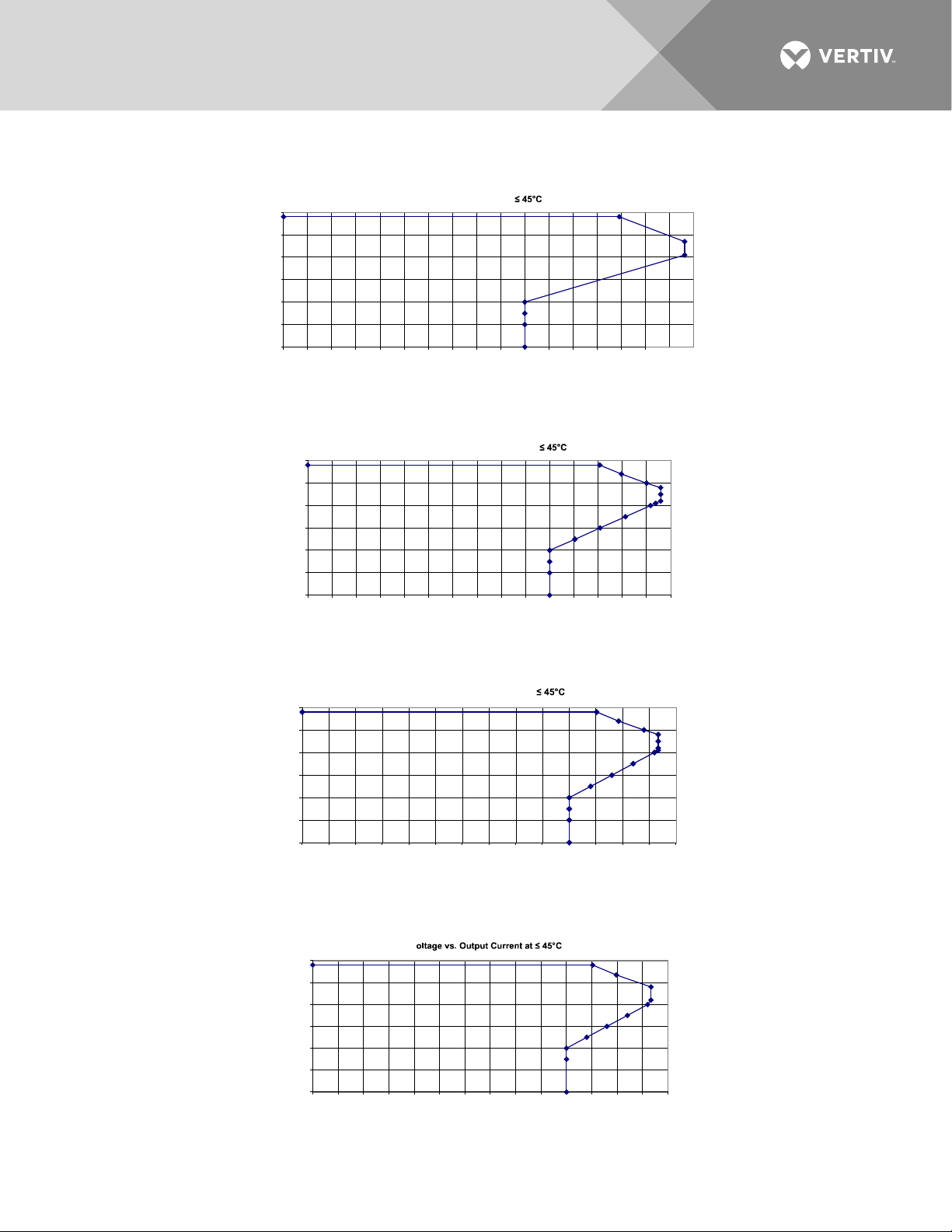
• Output Characteristics: Refer to Figure 1, Figure 2, Figure 3, and Figure 4 for graphs of rectifier output
voltage vs. output current.
Vertiv | NetSure Rectifier Module User Manual (UM1R483500e) | Rev. R
Page 8

8
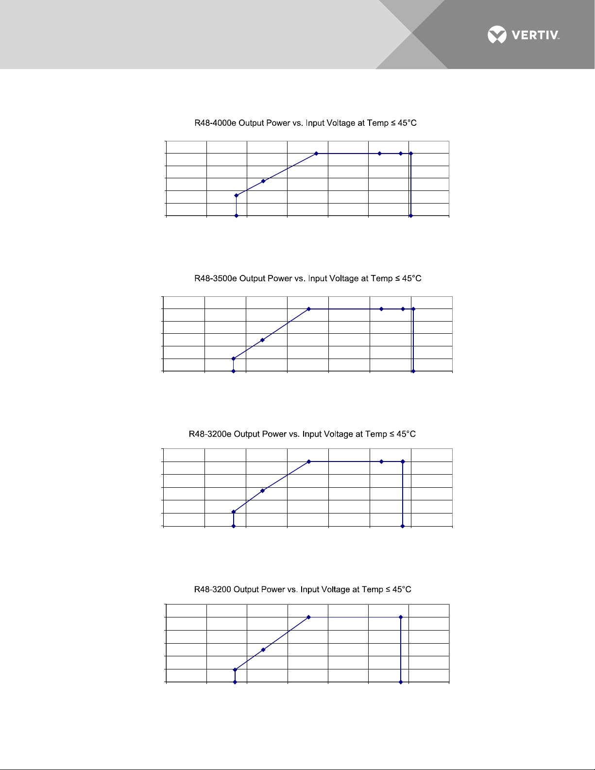
• Power Derating Based on Input Voltage: The rectifier power varies with changes in input voltage and
output voltage. It uses an advanced power limitation method. The lower input threshold is 85 VAC. The
rectifier can provide its maximum rated power (4000 W, 3500 W, or 3200 W) as long as the input
voltage is within the range of 176 VAC to 290 VAC (R48-3200, R48-3200e) or 176 VAC to 305 VAC
(R48-3500e) or 185 VAC to 305 VAC (R48-4000e). Below 176 VAC (R48-3200, R48-3200e,
R48-3500e) or 185 VAC (R48-4000e), and down to 85 VAC, the rectifier will continue to operate
normally but will be in a power derating mode.
a) R48-4000e (1R484000e): See Figure 5.
b) R48-3500e (1R483500e): See Figure 6.
c) R48-3200e (1R483200e): See Figure 7.
a) R48-3200 (1R483200): See Figure 8.
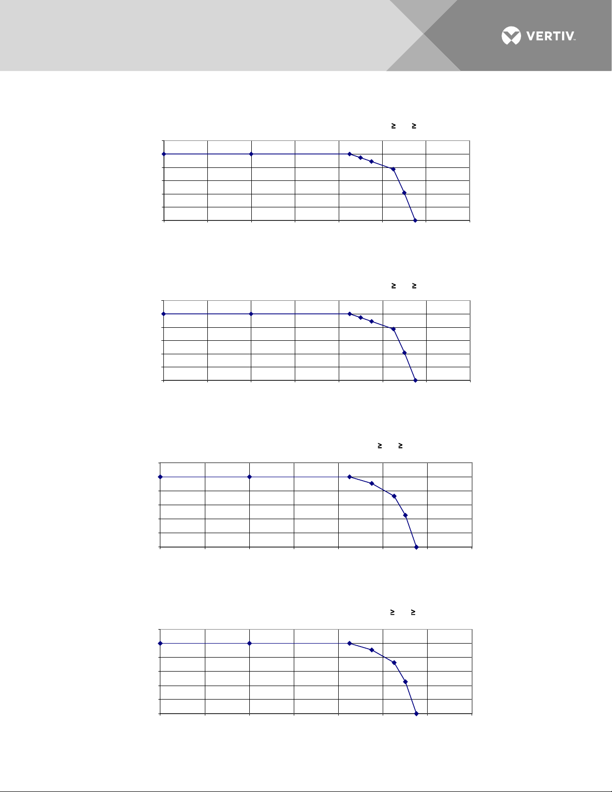
• Power Derating Based on Temperature: The rectifier delivers full power when operating at an ambient
temperature of +45 °C (+113 °F) or below. Each rectifier continuously monitors the ambient temperature
surrounding the power conversion circuit. If this temperature for any reason (such as a high ambient
temperature or failed fan) increases above approximately +45 °C (+113 °F), the rectifier will not shut
down. Rather, the rectifier limits its maximum output power to maintain the temperature of the power
conversion circuit within design parameters. Operation between +45 °C (+113 °F) and +75 °C (+158 °F)
will result in output power being decreased. Full power capability is restored when the temperature
decreases to below approximately +45 °C (+113 °F). Refer to Figure 9, Figure 10, Figure 11, and Figure
12 to view the relationship between the output power and the ambient temperature.
a) Rectifier 1R484000e provides a minimum of 3200 watts at 65 °C and from 48.0 VDC to 58.0 VDC.
b) Rectifier 1R483500e provides a minimum of 2700 watts at 65 °C and from 48.0 VDC to 58.0 VDC.
c) Rectifiers 1R483200 and 1R483200e provide a minimum of 2320 watts at 65 °C and from 48.0 VDC
to 58.0 VDC.
WARNING! The module is rated for continuous operation at full output power up to +45 °C (+113 °F).
Operation between +45 °C (+113 °F) and +75 °C (158 °F) will result in output power decrease. Operation
1
above +75 °C (+158 °F) is considered abnormal and should be used on a temporary
1
Temporary Operation at Abnormal Temperature: Temporary operation is defined as a period of
basis only.
not more than eight consecutive hours per day, and a total of not more than 15 days in a year.
(This refers to a total of 120 hours in any given year, but no more than 15 occurrences in that oneyear period.)
Vertiv | NetSure Rectifier Module User Manual (UM1R483500e) | Rev. R
Page 9
9
R48-4000e Output Voltage vs. Output Current at
0
10
20
30
40
50
60
0 5 10 15 20 25 30 35 40 45 50 55 60 65 70 75 80 85
Output C urr ent (A)
Output
Voltage (V)
R48-3500e Output Voltage vs. Output Current at
0
10
20
30
40
50
60
0 5 10 15 20 25 30 35 40 45 50 55 60 65 70 75
Output C urr ent (A)
Output Voltage (V)
R48-3200e Output Voltage vs. Output Current at
0
10
20
30
40
50
60
0 5 10 15 2
0 25 30
35 40 45 50 5
5 60 65 70
Output Curr ent (A)
Output Voltage (V)
R48-3200 Output V
0
10
20
30
40
50
60
0 5 10 15 20 25 30 35 40 45 50 55 60 6 5 70
Output C urr ent (A)
Output Voltage (V)
Figure 1:
Figure 2:
Output Voltage vs. Output Current [R48-4000e (1R484000e)]
Output Voltage vs. Output Current [R48-3500e (1R483500e)]
Figure 3:
Figure 4:
Vertiv | NetSure Rectifier Module User Manual (UM1R483500e) | Rev. R
Output Voltage vs. Output Current [R48-3200e (1R483200e)]
Output Voltage vs. Output Current [R48-3200 (1R483200)]
Page 10
10
0
20
40
60
80
100
120
0 50 100 150 200 250 300 350
Input Voltage (Vac)
% of output power
0
20
40
60
80
100
120
0 50 100 150 200 250 300 350
Input Voltage (Vac)
% of output power
0
20
40
60
80
100
120
0 50 100 150 200 250 300 350
Input Voltage (Vac)
% of output power
0
20
40
60
80
100
120
0 50 100 150 200 250 300 350
Input Voltage (Vac)
% of output power
Figure 5:
Figure 6:
Power Derating Based on Input Voltage (R48-4000e [1R484000e])
Power Derating Based on Input Voltage (R48-3500e [1R483500e])
Figure 7:
Figure 8:
Vertiv | NetSure Rectifier Module User Manual (UM1R483500e) | Rev. R
Power Derating Based on Input Voltage (R48-3200e [1R483200e])
Power Derating Based on Input Voltage (R48-3200 [1R483200])
Page 11
11
Temperature (°C)
0
20
40
60
80
100
120
-40 -20 0 20 40 60 80 100
% of output power
R48-4000e Output Power vs. Temperature at 305 Vac Vin 185 Vac
Temperature (°C)
0
20
40
60
80
10
0
120
-
40 -2
0 0 2
0 40
60 80
100
% of output power
R48-3
500
e Output Power vs. Temperature at 305 Vac Vin 1
76
V
ac
0
20
40
60
80
100
120
-40 -20 0 20 40 60 80 100
Temperature (°C)
% of output po
wer
R48-3200e Output Power
vs. T
emperature at 290 Vac Vin 17
6 Vac
R48-3200 Output Power vs. Temperature at 2
90 Vac Vin 176 Vac
0
20
40
60
80
100
120
-40 -20 0 20 40 60 80 100
Temperature (°C)
% of output power
Figure 9:
Figure 10:
Typical Thermal Power Limit Curve (R48-4000e [1R484000e])
Typical Thermal Power Limit Curve (R48-3500e [1R483500e])
Figure 11:
Figure 12:
Vertiv | NetSure Rectifier Module User Manual (UM1R483500e) | Rev. R
Typical Thermal Power Limit Curve (R48-3200e [1R483200e])
Typical Thermal Power Limit Curve (R48-3200 [1R483200])
Page 12

12
• Regulation:
a) Output Voltage Tolerance:
Output voltage tolerance:
< ± 0.2 % 25 A load +15 °C to +35 °C
< ± 0.5 % 25 A load -5 °C to +55 °C
Static regulation, including input voltage variation and temperature variation:
< ± 0.5 % 5 % to 100 % load +15 °C to +35 °C
< ± 1 % 5 % to 100 % load -5 °C to +55 °C
Uin = 176 VAC to 290 VAC for R48-3200 and R48-3200e, 176 VAC to 305 VAC for R48-3500e,
185 VAC to 305 VAC for R48-4000e, f = 45 Hz to 65 Hz
Output voltage decreases with increased output current.
Overshoot of output voltage at startup ≤ ±1 %.
b) Dynamic Response Characteristic (at rated input and output voltage):
Response time ≤ 200 us and overshoot ≤ 5 % for load changes at
50 % - 25 % - 50 % and 50 % - 75 % - 50 %.
Overshoot or undershoot ≤ 5 % and output recovers within ±1 % of regulation band in ≤ 4 ms for load
changes at 10 % - 90 % and 90 % - 10 %. (Telcordia GR-947.)
• Filtering (with or without battery):
a) Voice Band Noise: Complies with Telcordia GR-947-CORE.
1. R48-3200, R48-3200e, R48-3500e: Output noise according to Telcordia GR-947-CORE: < 32
dBrnC between 180 VAC ~ 290 VAC input and 10 % to 100 % load (output voltage > 42 V, for
any application with > 1 rectifier).
2. R48-4000e: Output noise according to Telcordia GR-947-CORE: < 38 dBrnC between 180
VAC ~ 290 VAC input and 20 % to 70 % load (output voltage > 42 V, for any application with > 1
rectifier).
3. R48-3200, R48-3200e, R48-3500e: Psophometric noise is ≤ 1 mV between 180 VAC ~ 290 VAC
input and 10 % to 100 % load (output voltage > 42 V) and 16.66 Hz to 6000 Hz. (for any
application with > 1 rectifier).
4. R48-4000e: Psophometric noise is < 2 mV between 180 VAC ~ 290 VAC input and 20 % to
70 % load (output voltage > 42 V) and 16.66 Hz to 6000 Hz. (for any application with > 1
rectifier).
b) Wide Band Noise: Complies with Telcordia GR-947-CORE.
1. Typically 130 millivolt peak-to-peak. Does not exceed 250 millivolt peak-to-peak.
2. Typically 13 millivolts rms. Does not exceed 30 millivolt rms.
• Output Discharge: The output capacitors automatically discharge when the rectifier is disconnected
from the batteries and AC is turned OFF. Time constant is less than 1 minute.
Vertiv | NetSure Rectifier Module User Manual (UM1R483500e) | Rev. R
Page 13

13
• Power Interruption: The rectifier starts when connected to a fully discharged battery or capacitor bank
(bus voltage > 15 V) without operating protective devices or requiring the shedding of load or needing
any manual intervention. The rectifier starts under all line and environmental conditions, when the
output terminals are connected to an impedance of less than 15 milliohms.
• Stability Criteria: Complies with GR947 Core R3-20. Stability criteria: > 30 deg. of phase margin when
gain is unity (0 dB) and gain down to < - 6 dB when phase is 180 deg.
AC Input Ratings
• 1R484000e Voltage: Nominal 208 VAC / 240 VAC / 277 VAC, single phase, 50 Hz / 60 Hz, with an
operating range of 185 VAC to 305 VAC. Acceptable input frequency range is 45 Hz to 65 Hz.
• 1R483500e Voltage: Nominal 208 VAC / 240 VAC / 277 VAC, single phase, 50 Hz / 60 Hz, with an
operating range of 176 VAC to 305 VAC. Acceptable input frequency range is 45 Hz to 65 Hz.
• 1R483200/1R483200e Voltage: Nominal 208 VAC /240 VAC, single phase, 50 Hz / 60 Hz, with an
operating range of 176 VAC to 290 VAC. Acceptable input frequency range is 45 Hz to 65 Hz.
• Safe Voltage: The system can tolerate 415 VAC without damage.
• Harmonic Content (THD): < 5 % THD at 50 % - 100 % load. The voltage source must have a voltage
THD of < 1.1 %.
The rectifier complies with EN61000-3-2.
• Inrush Current: Peak does not exceed 1.5 times the steady state peak value of the input current at full
load, nominal input voltage, and for any duration of AC input interrupts. Under the above conditions,
standard AC distribution circuit breakers will not trip.
Vertiv | NetSure Rectifier Module User Manual (UM1R483500e) | Rev. R
Page 14
14
10
2.194
457.92
435.10
0.950
92.18
116.1257
30
6.109
1271.20
1255.45
0.988
95.30
201.3862
50
10.138
2102.68
2094.08
0.996
95.19
343.7722
80
16.454
3395.71
3389.90
0.998
93.99
695.3344
90
18.645
3841.68
3835.70
0.998
93.42
861.3961
10
1.941
467.48
432.73
0.926
92.68
108.1087
50
8.767
2101.49
2085.36
0.992
95.58
314.5833
70
12.329
2947.99
2937.02
0.996
94.96
505.2075
90
16.021
3820.50
3811.89
0.998
94.00
780.5918
10
1.762
490.21
431.00
0.879
93.06
102.0867
30
4.643
1289.53
1247.46
0.967
95.92
173.7077
50
7.607
2108.78
2078.65
0.986
95.90
290.8691
70
10.647
2945.46
2924.85
0.993
95.37
462.1862
90
13.782
3806.88
3791.54
0.996
94.50
711.7225
100
15.388
4246.35
4232.67
0.997
94.04
860.98
277
274
15.4
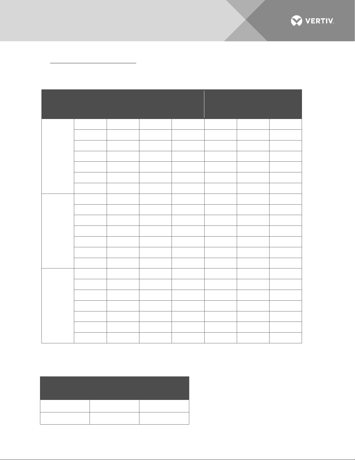
• Typical Input Data (1R484000e): 60 Hz input.
a) System output is initially adjusted to 53.5 VDC as measured at the system sense points at 50 % of
full load and nominal input. “Percent of Full Load” refers to percent of 74.7 amperes.
Nominal
Input
Voltage
208
240
Percent
of Full
Load
Input
Current
(Amperes)
Input
VA
Input
Watts
Power
Factor
Efficiency
%
Heat
Dissipation
BTU/Hr
70 14.312 2958.40 2952.19 0.998 94.47 557.1881
100 20.885 4298.34 4292.11 0.998 92.73 1064.971
30 5.324 1279.22 1251.30 0.978 95.62 187.0544
80 14.152 3379.85 3370.42 0.997 94.54 628.0714
100 17.915 4266.63 4258.59 0.998 93.46 950.5522
277
80 12.201 3372.95 3355.44 0.995 94.96 577.1815
b) Maximum Input Current: at 100% of full load with output adjusted to 58 VDC as measured at the
shelf output terminals.
Nominal Input
Voltage
Input
Voltage
208/240 204 21.0
Vertiv | NetSure Rectifier Module User Manual (UM1R483500e) | Rev. R
Input Current
(Amperes)
Page 15
15
0
0.42
87
11
0.125
--
34.5
25
4.20
872
853
0.977
95.28
132.7
50
8.20
1700
1690
0.994
96.00
221.2
100
16.66
3441
3435
0.998
94.31
651.1
110
18.32
3781
3775
0.998
93.68
800.1
0
0.49
118
11
0.920
--
34.2
50
7.11
1704
1684
0.988
96.34
201.0
75
10.65
2547
2535
0.995
95.86
343.9
110
15.75
3758
3748
0.997
94.36
703.8
0
0.54
149.6
8.6
0.572
--
29.35
25
3.09
856.4
840.6
0.982
96.29
212.11
50
6.1
1691.8
1675
0.990
96.29
212.11
75
9.15
2535.6
2524.8
0.996
95.77
364.85
110
13.58
3753.8
3748
0.988
94.51
702.18
120
13.58
3753.9
3748.9
0.994
94.52
700.84
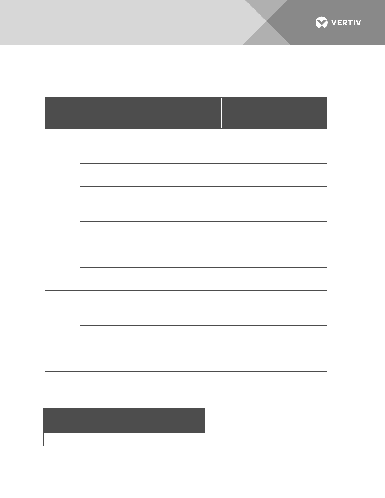
• Typical Input Data (1R483500e): 60 Hz input.
a) System output is initially adjusted to 54.48 VDC as measured at the system sense points at 50 % of
full load and nominal input. “Percent of Full Load” refers to percent of 60 amperes.
Nominal
Input
Voltage
208
240
Percent
of Full
Load
Input
Current
(Amperes)
Input
VA
Input
Watts
Power
Factor
Efficiency
%
Dissipation
BTU/Hr
75 12.34 2553 2546 0.997 95.48 378.6
120 18.36 3790 3782 0.998 93.29 854.6
25 3.66 877 850 0.969 95.59 123.2
100 14.34 3423 3414 0.997 94.90 576.4
120 15.79 3768 3757 0.997 93.91 765.4
Heat
277
100 12.26 3394.5 3388.8 0.998 94.94 584.78
b) Maximum Input Current: at 100% of full load with output adjusted to 58 VDC as measured at the
shelf output terminals.
Nominal Input
Voltage
Input
Voltage
Input Current
(Amperes)
208/240/277 176 21.60
Vertiv | NetSure Rectifier Module User Manual (UM1R483500e) | Rev. R
Page 16
16
0
0.397
82.6
9
0.111
--
30.72
25
3.7451
779.7
773.8
0.992
95.49
119.04
50
7.4189
1543.9
1540.7
0.998
95.86
217.91
100
15.0624
3118.6
3118.1
0.999
94.38
597.58
110
16.551
3418.3
3417.9
0.999
93.93
707.78
0
0.4651
111.8
8.8
0.804
--
30.03
50
6.4286
1545.1
1536.3
0.994
96.14
202.43
75
9.6608
2318.1
2313.3
0.998
95.65
343.73
110
14.2095
3399.5
3397.2
0.999
94.50
637.95
208/240
176
19.30
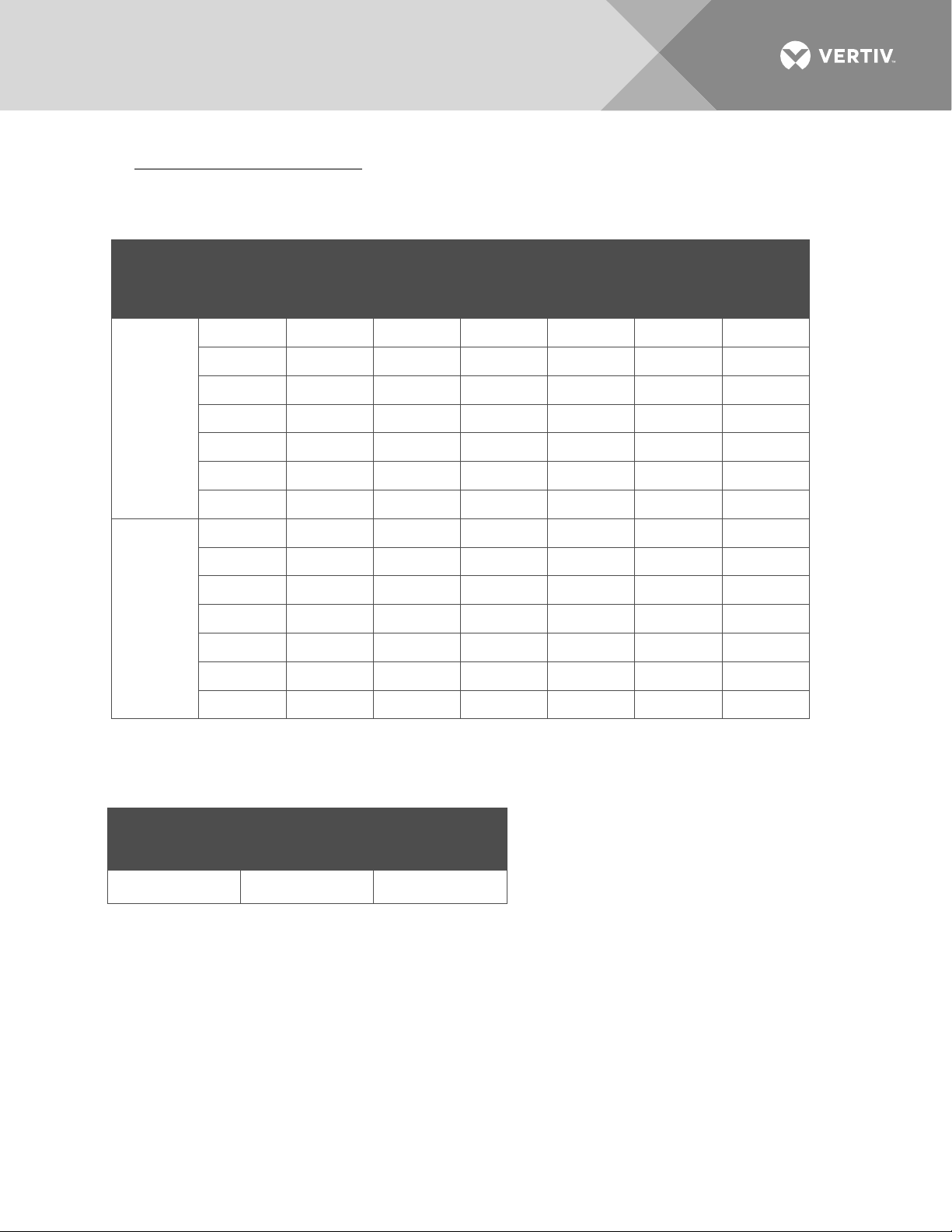
• Typical Input Data (1R483200e): 60 Hz input.
a) System output is initially adjusted to 54.48 VDC as measured at the system sense points at 50 % of
full load and nominal input. “Percent of Full Load” refers to percent of 55 amperes.
Nominal
Input
Voltage
208Vac
(60Hz)
240Vac
(60Hz)
Percent
of Full
Load
Input
Current
(Amperes)
Input
VA
Input
Watts
Power
Factor
Efficiency
%
Heat
Dissipation
BTU/Hr
75 11.2183 2325.1 2323.2 0.999 95.23 378.51
120 16.5356 3419 3418.3 0.999 93.91 710.44
25 3.2515 780.2 772.1 0.990 95.74 112.17
100 12.963 3103.8 3100.5 0.999 94.92 537.14
120 14.2234 3402.7 3399.9 0.999 94.50 638.09
b) Maximum Input Current: at 100% of full load with output adjusted to 58 VDC as measured at the
shelf output terminals.
Nominal Input
Voltage
Vertiv | NetSure Rectifier Module User Manual (UM1R483500e) | Rev. R
Input
Voltage
Input Current
(Amperes)
Page 17
17
0
0.62
127
69
0.542
--
235.25
25
4.13
856
842
0.988
88.9
319.31
50
7.92
1644
1639
0.997
91.0
479.51
100
16.02
3298
3297
0.998
90.9
1020.09
110
17.28
3561
3558
0.998
90.5
1156.27
0
0.68
163
66
0.612
--
225.31
50
6.89
1648
1633
0.994
91.9
453.62
75
10.23
2445
2441
0.998
92.1
654.78
110
14.84
3538
3534
0.998
91.3
1050.24
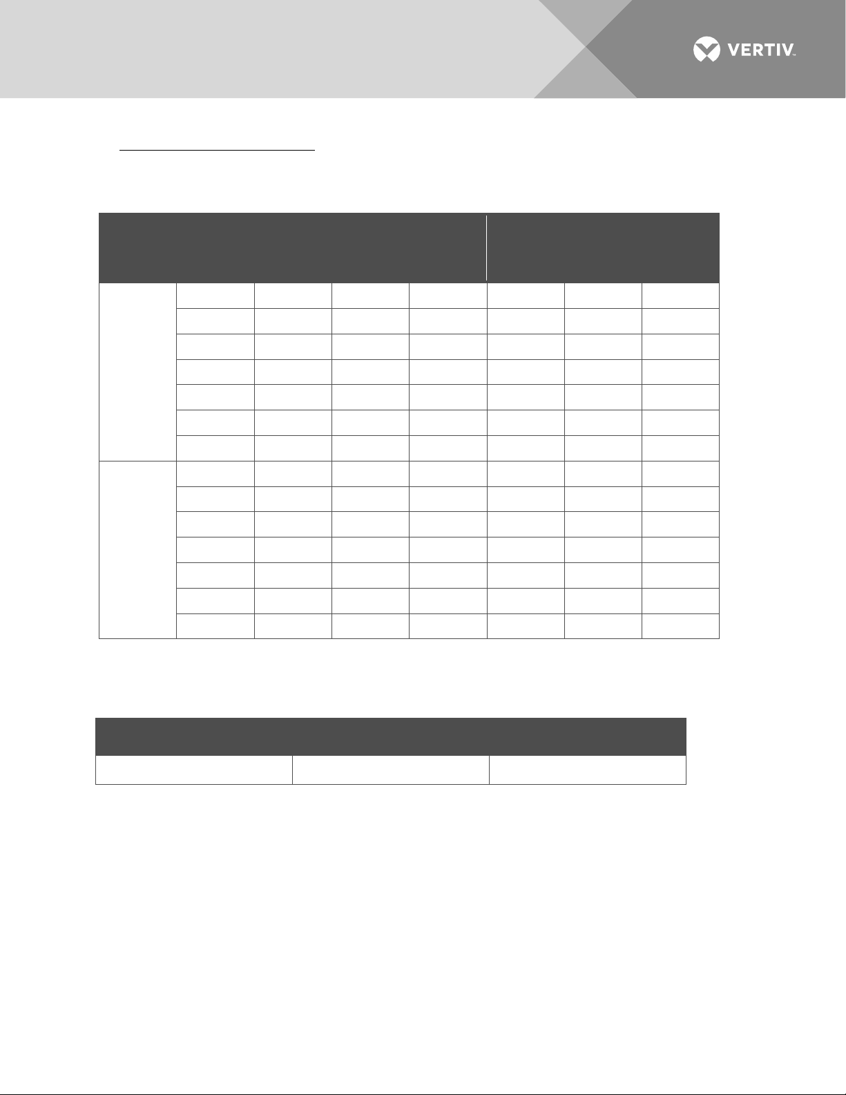
• Typical Input Data (1R483200): 60 Hz input.
a) System output is initially adjusted to 54.48 VDC as measured at the system sense points at 50 % of
full load and nominal input. “Percent of Full Load” refers to percent of 55 amperes.
Nominal
Input
Voltage
208
240
Percent
of Full
Load
Input
Current
(Amperes)
Input
VA
Input
Watts
Power
Factor
Efficiency
%
Heat
Dissipation
BTU/Hr
75 11.87 2457 2453 0.998 91.6 701.88
120 16.88 3478 3477 0.998 89.9 1208.42
25 3.65 865 846 0.977 88.7 325.42
100 13.68 3269 3265 0.998 91.8 917.81
120 14.46 3455 3454 0.998 90.5 1118.21
b) Maximum Input Current: at 100% of full load with output adjusted to 58 VDC as measured at the
shelf output terminals.
Nominal Input Voltage Input Voltage Input Current (Amperes)
208/240 176 20.42
Vertiv | NetSure Rectifier Module User Manual (UM1R483500e) | Rev. R
Page 18
18
Efficiency Curve
Load (% of rated load)
Efficiency (%)
84
86
88
90
92
94
96
98
0
10
20 30
40 50 60 70
80 90
100
Effici
ency Curve
Load (% of rated load)
Efficiency (%)
90.00%
91.00%
92.00%
93.00%
94.00%
95.00%
96.00%
97.00%
98.00%
0 10 20 30 40 50 60 70
200Vac
230Vac
220Vac
250Vac
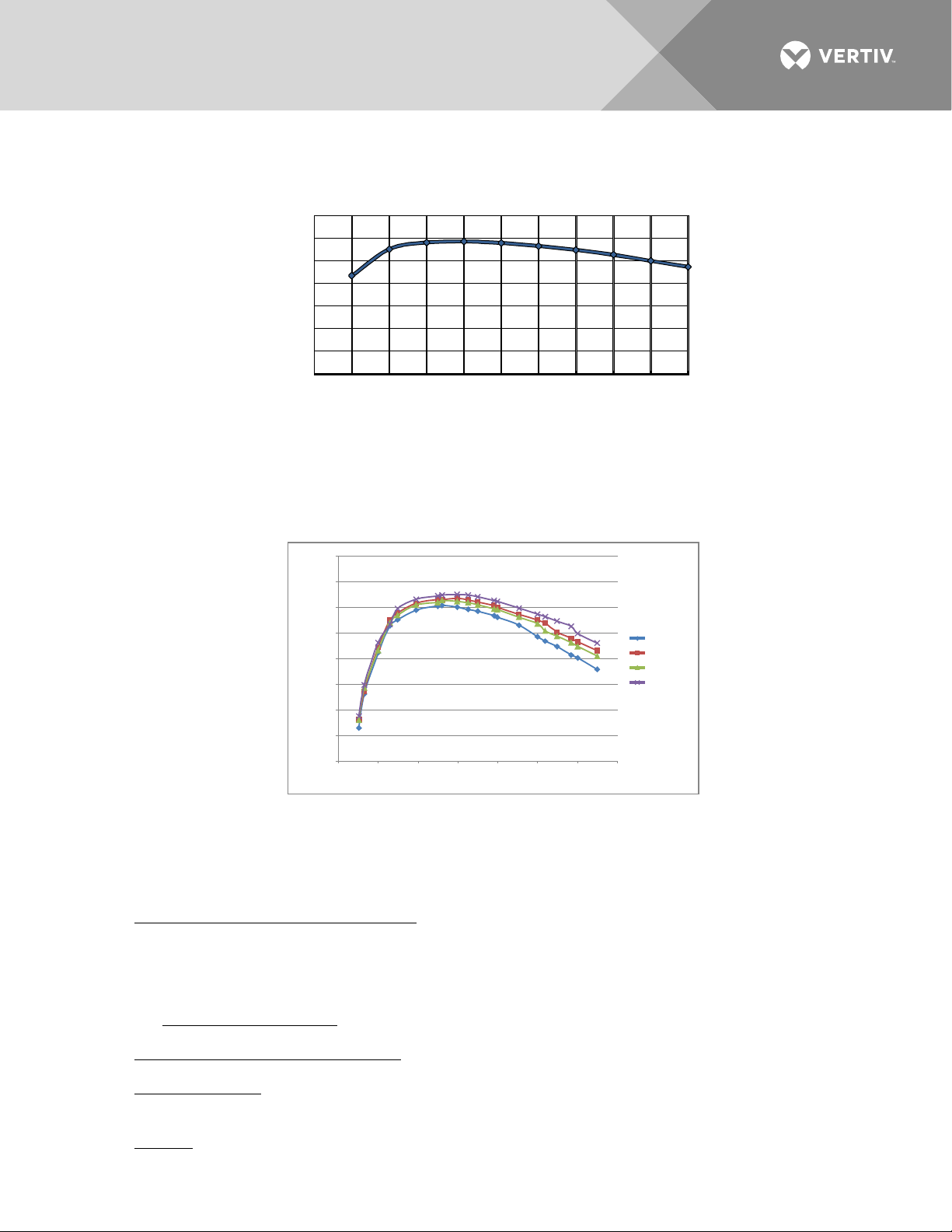
Figure 13:
Figure 14:
Efficiency Curve [R48-4000e (1R484000e)]
Efficiency Curve [R48-3500e (1R483500e)]
Environmental Ratings
• Operating Ambient Temperature Range:
Vertiv | NetSure Rectifier Module User Manual (UM1R483500e) | Rev. R
a) -40 °C (-40 °F) to +75 °C (+167 °F) with derating output.
b) -40 °C (-40 °F) to +45 °C (+113 °F) with full power performance.
c) Temperature Coefficient: 0.01 % per degrees Celsius.
• Storage Ambient Temperature Range: -40 °C (-40 °F) to 75 °C (+167 °F).
• Relative Humidity: This rectifier is capable of operating in an ambient relative humidity range of 0 % to
95 %, non-condensing.
• Altitude: 2000 m (6560 ft) at full power (power limited for heights above 2000 m).
Page 19

19
• Surge Protection: Compliance with EN61000-4-5 Installation Class 4, and capable of withstanding
surges per ANSI/IEEE C 62.41 1999 Category B3 across the input terminals.
NOTE!
This level of protection is a widely used standard for telecommunications power equipment. As
with all such equipment, it is the end user's responsibility to provide an adequately sized Surge
Suppression Device at the commercial power service entrance of the building that reduces all incoming
surges to levels below the classes/categories stated for the equipment.
• Ventilation Requirements: The rectifiers are fan cooled and utilize front to back forced ventilation. A
rectifier must be mounted so ventilating openings are not blocked and temperature of the air entering
the rectifier does not exceed the Operating Ambient Temperature Range stated above.
• Single Rectifier Audible Noise:
a) At 25 °C ≤ 53 dB(A) with fan in high speed; Measurement made at 0.6 m distance in front of rectifier
and at same horizontal line of the middle of rectifier.
b) At 25 °C ≤ 45 dB(A) with fan in low speed; Measurement made at 1 m distance in front of rectifier
and at same horizontal line of the middle of rectifier.
• EMI/RFI Suppression:
a) Rectifiers operating in an approved rectifier Mounting Shelf conform to the requirements of FCC
rules Part 15, Subpart B, Class B for Radiated and Conducted emissions limits.
b) Rectifiers operating in an approved rectifier Mounting Shelf conform to the requirements of
European Norm, EN55022, Class B for Radiated and Conducted emissions limits.
Compliance Information:
• Safety Compliance: This unit meets the requirements of UL 60950-1, Standard for Information
Technology Equipment, and is UL Recognized as a power supply for use in Telephone, Electronic Data
Processing or Information Processing Equipment. This unit meets the requirements of CAN/CSA 22.2,
No. 60950-00 and is tested and Certified by UL ("c UR")as a Component Type Power Supply.
• The rectifiers are RoHS compliant, 5/6.
Standard Features
• Type of Power Conversion Circuit: High frequency.
• Constant Voltage Mode: For any initial output voltage setting from 47 VDC to 58 VDC, output voltage
remains constant regardless of load. This is the normal operating condition, in which loads are being
supplied and batteries are float charged. Rectifiers operate in the Constant Voltage Mode unless load
increases to the point where the product of load current and output voltage is approximately 4000 W,
3500 W, or 3200 W (depending on rectifier model).
• Constant Power Mode: As load increases above approximately 4000 W, 3500 W, or 3200 W (depending
on rectifier model) (non-adjustable), output current continues to increase, but output voltage decreases
as required to maintain constant output power. Rectifiers operate in the Constant Power Mode unless
load continues to increase to the point where the current limit setting is reached.
• Constant Current Mode: If load increases to the current limit setting, output voltage decreases linearly
to maintain output current at the current limit setting.
Vertiv | NetSure Rectifier Module User Manual (UM1R483500e) | Rev. R
Page 20

20
• Input Protection:
a) Fuse: On the input, two UL recognized fuses are used, not user-replaceable.
b) Input Voltage Protection: Derating from 85 VAC to 176 VAC (R48-3200, R48-3200e, R48-3500e) or
85 VAC to 185 VAC (R48-4000e). Withstand 415 VAC input without damage.
1. The rectifier will shut down at low or high voltage input; low voltage disable point: 80 V ±3 V;
Hysteresis at least 15 VAC for restart. High voltage disable point: 295 V ±5 V for R48-3200 and
R48-3200e, 310 V ±5 V for R48-3500e and R48-4000e; Hysteresis at least 10 VAC for restart.
2. Between 85 VAC to 176 VAC (R48-3200, R48-3200e, R48-3500e) or 85 VAC to 185 VAC
(R48-4000e) the output power will be derated linearly according to input voltage per Figure 5,
Figure 6, Figure 7, and Figure 8.
3. Over Voltage Isolation: The rectifier will be disconnected from the AC input when a preset non-
adjustable value is reached.
• AC Fail Alarm: The rectifier issues an "AC Fail Alarm" when AC input voltage drops below 164 VAC. This
alarm clears when AC input voltage recovers above 169 VAC. This level can be set by the controller.
• Output Protection:
a) Overload / Reverse Current: An output fuse is provided on each rectifier. This fuse is not customer
replaceable. The rectifier can be plugged into or pulled out of a shelf while operating, without
damage or opening the fuse.
b) Current Limiting: The maximum current delivered by the rectifier can be set via the controller from
10 % to 121 % of its rating at maximum rated output voltage. Output Current Limit Error: ≤ ±1.5 A.
c) High Voltage Shutdown:
1. Adjustable Control: If rectifier output voltage exceeds an adjustable preset value and the
rectifier is delivering more than 10 % of its rated current, the rectifier shuts down. (Adjustable
from 56 VDC to 59 VDC via the controller. The restart hysteresis is 0.5 V ±0.2 V.)
The rectifier then restarts and a HVSD restart timer starts (time value configurable via the
controller, factory default is 5 minutes). If output voltage again exceeds the high voltage
shutdown value before the HVSD restart timer expires, the rectifier shuts down and locks out.
Manual restart is then required (by turning power to the rectifier off or by removing the rectifier,
waiting until the LEDs on the rectifier extinguish, then turning power to the rectifier on or reinserting the rectifier). If the rectifier does not experience a high voltage condition before the
HVSD restart timer expires, the restart circuit is reset.
If two or more rectifiers are paralleled, only the rectifier causing the high voltage condition shuts
down.
2. Backup: If rectifier output voltage exceeds 59.5 V ±0.5 V (non-adjustable) and the rectifier is
delivering more than 10 % of its rated current, the rectifier shuts down. The rectifier then
restarts and a HVSD restart timer starts (time value configurable via the controller, factory
default is 5 minutes). If output voltage again exceeds the high voltage shutdown value before
the HVSD restart timer expires, the rectifier shuts down and locks out. Manual restart is then
required (by turning power to the rectifier off or by removing the rectifier, waiting until the LEDs
on the rectifier extinguish, then turning power to the rectifier on or re-inserting the rectifier).
Vertiv | NetSure Rectifier Module User Manual (UM1R483500e) | Rev. R
Page 21

21
• Over-Temperature Protection: The rectifier provides over temperature protection by derating output
power and recovers automatically.
• Active Load Sharing: The rectifier uses advanced digital active load sharing technology that maintains
balancing to within 3 % of rated current.
• Hot Swappable: The rectifier is designed to be plug-and-play. The rectifier can be inserted or removed
from a live DC power system with no damage. When the rectifier is plugged into the system, the system
output voltage will not be affected.
• High Temperature Alarm: Each rectifier continuously monitors the ambient temperature surrounding
the power conversion circuit. If this temperature exceeds a preset non-adjustable value, local and
extended rectifier Fail alarms are activated. The alarms will automatically be removed when the ambient
temperature surrounding the power conversion circuit decreases to below a preset non-adjustable
value.
• Cooling: Each rectifier contains a fan for front-to-back force air-cooling.
a) Fan Fault Protection: The rectifier shuts down and its alarm indicator (red) flashes if the fan fails.
Fan failure is detected and reported to controller. The fans are field replaceable.
b) Fan Control: Fan speed is continuously variable. When input voltage is within normal range, the
built-in processor adjusts fan speed according to the rectifier Module’s internal temperature and
output power. For example, a higher temperature or output power increases the fan speed. This
feature can be disabled via the controller, allowing the fan to run at full speed regardless of
temperature.
• Paralleling: This rectifier may be connected in parallel with any rectifier of the same polarity and
adjusted to the same output voltage.
• Output Current Walk-In:
a) Normal Start:
1. Start up time, defined as beginning at AC switch on and ending when full output power has
been reached, consists of two time intervals, the delay period and the output voltage rampup
period.
2. During the delay period the output voltage will be zero.
3. Start up time (AC on, till full power): ≤ 5 seconds.
4. Output voltage ramp up period, t: 50 ms ≤ t ≤ 150 ms. (10 % to 90 % of full power)
5. The rectifier will not suffer any damage, when subjected to repetitive AC switch on / switch off
operations.
b) Current Walk-In (if enabled via controller):
1. 90 % load in > 8 S, 100 % load in < 124 s.
2. According to Telcordia GR-947-CORE, R3-19.
Vertiv | NetSure Rectifier Module User Manual (UM1R483500e) | Rev. R
Page 22

22
• Communication Failure: The rectifier’s protection indicator (yellow) will flash should it experience a
communication failure. The failure information will be reported to the controller and the controller will
process the failure accordingly. During a communication failure, in order to protect the battery, the
rectifier output voltage will automatically be adjusted as follows.
- The rectifier default factory output voltage is 53.5 V.
- Once power is applied to the rectifier and the rectifier is recognized by the controller, the output
voltage is updated to the setting programmed into the controller.
- If communications with an SCU+ controller is lost, rectifier output voltage goes to a default value
programmed into the controller (this is a separate programmable parameter from the output voltage
setting).
- If communications with an ACU+ or NCU controller is lost, rectifier output voltage goes to the last
communicated float output voltage setting in the controller (the last communicated float output
voltage setting is stored in the rectifier).
- The rectifier will revert to normal operation once normal communication to the controller is restored.
• Rectifier Output Current Imbalance:
a) When the average current of all rectifier modules is greater than 20 % of full rated current, and the
difference between local rectifier current and average current is greater than 16 % of full rated
current, the yellow protection indicator will illuminate.
b) When the average current of all rectifier modules is greater than 10 % of full rated current, and local
rectifier current is less than 1.5 % of full rated current, then the red fault indicator will illuminate.
• Monitoring Function: The rectifier has a built-in advanced DSP that monitors and controls the operation
of the rectifier. The DSP also communicates with the controller in real time through the CAN bus. Table
1 lists the different commands and information exchanged between the rectifier and the controller.
• External Control Circuits: Provided via the associated controller. Refer to the separate Power System
documentation for a complete description of available external control circuits.
• External Alarm Circuits: Provided via the associated controller. Refer to the separate Power System
documentation for a description of available external alarms.
Mechanical Specifications
• Dimensions:
a) Millimeters: 132.0 (Height) X 85.3 (Width) X 287.0 (Depth)
b) Inches: 5.20 (Height) X 3.36 (Width) X 11.3 (Depth)
• Weight: 3.5 kg (7.7 lbs).
• Indicators:
a) Power (Green)
b) Protection (Yellow)
c) Alarm (Red)
Vertiv | NetSure Rectifier Module User Manual (UM1R483500e) | Rev. R
Page 23

23
Table 1:
Exchange of Information between Rectifier and Controller
Commands / signals that can be
received by the Rectifier Module
from the Controller.
• Turn On/Off
• Current Walk-in On/Off
• HVSD (High Voltage Shutdown)
Reset
• Current Limit Adjustment
• Voltage Regulation
Information gathered by the
Controller from the Rectifier Module.
• Input Voltage
• Output Voltage
• Output Current
• Current Limit Setting
• Temperature
• Over Voltage Setting
• On/Off Status
• Fault Alarms, such as:
HVSD
Fan Fail
• Protection Alarms, such as:
Input Voltage Protection
Inner DC Bus Voltage Protection
High Temperature Protection
• Thermal Derating
• AC Derating
• AC Fail
• Imbalance Output Current
• Address
• Code
• Date
• Software Version
Hardware Version
•
OPERATION
AC Input Protection Device Requirements/Recommendations
Refer to the system documentation supplied with the system the rectifier is installed in.
Local Indicators
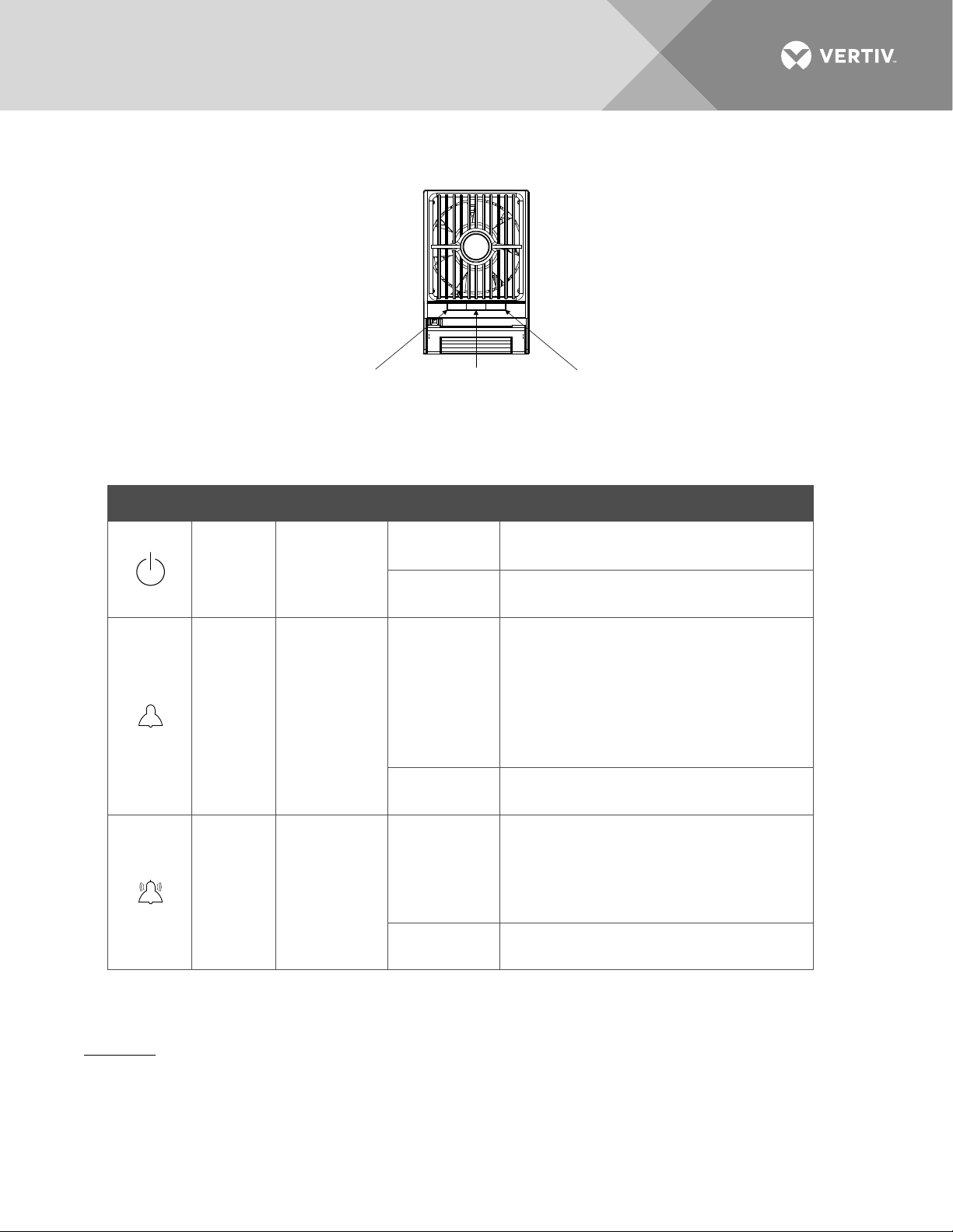
Location and Identification: Refer to Figure 15.
Description: There are three (3) indicators located on the rectifier’s front panel. The functions of these
indicators are as shown in Table 2.
Vertiv | NetSure Rectifier Module User Manual (UM1R483500e) | Rev. R
NOTE!
rectifier) or AC voltage at the input terminals.
DC voltage must be present at the rectifier output terminals (from battery or an operating
Page 24
24
The rectifier is being identified by the
Loss of communication with the controller
Fan not operating (rectifier module shuts
Power Indicator
(Green)
Protection Indicator
(Yellow)
Alarm Indicator
(Red)
Figure 15:
Table 2:
Local Indicators
Local Indicator Locations
Indicator Normal State Alarm State Alarm Cause
No input voltage.
Internal input fuse open.
controller.
Power
(Green)
Off
On
Flashing
AC input under/over voltage.
PFC output under/over voltage.
Moderate load sharing imbalance.
Protection
(Yellow)
On
Off
Rectifier not inserted into the slot
completely.
Rectifier in ECO Standby Mode when ECO
Mode is active in controller.
Flashing
(the rectifier can provide power).
Severe load sharing imbalance.
Rectifier output disabled for any reason,
Alarm
(Red)
Off
Flashing
On
including overvoltage shutdown and
internal output fuse open.
Rectifier addresses contradictory.
down).
Rectifier High Voltage Shutdown and Lockout Restart
Procedure
1. Turn the power to the rectifier off or remove the rectifier, wait 30 seconds or more (until the LEDs on
the rectifier extinguish), then turn the power to the rectifier on or re-insert the rectifier.
Vertiv | NetSure Rectifier Module User Manual (UM1R483500e) | Rev. R
Page 25
25
Installing Rectifiers
The rectifier is hot swappable. It can be installed with the system operating.
CAUTION! This rectifier module contains Double pole fusing; parts of the equipment that remain
energized might represent a hazard during servicing after operation of the fuse. If the rectifiers are
connected to a 3-phase system, the neutral line should also have a fuse.
WARNING! To prevent damage to the latching mechanism, ensure the handle is in the open position
when installing or removing a module. NEVER hold the handle in the closed position when installing a
module into a shelf.
Procedure
NOTE!
Refer to
Figure 16
as this procedure is performed.
1. Place the rectifier into an unoccupied mounting slot without sliding it in completely.
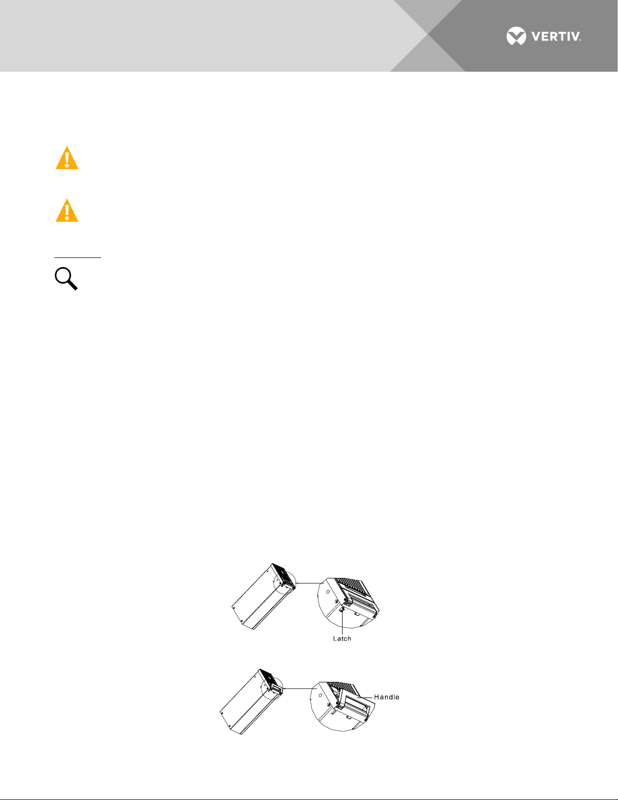
2. Click the rectifier handle in order to pop it forward out of the rectifier's front panel (this will also retract
the latch mechanism located on the underside of the rectifier). Refer to Figure 16 for latch mechanism
illustration.
3. Push the rectifier completely into the shelf.
4. Push the handle into the front panel of the rectifier. This locks the rectifier securely to the shelf.
5. Repeat the above steps for each rectifier being installed in the system.
6. After the rectifiers are physically installed in the mounting shelf(s), they are ready for operation
immediately after power is supplied to them.
7. Certain functions (i.e. rectifier current limit, rectifier addressing) may require adjustment when adding or
replacing a rectifier Module. Refer to the Power System documentation for instructions.
Figure 16:
Installing a Rectifier
Vertiv | NetSure Rectifier Module User Manual (UM1R483500e) | Rev. R
Page 26

26
TROUBLESHOOTING AND REPAIR
Troubleshooting
Rectifier Current Sharing Imbalance
When multiple rectifiers are operating in parallel and the load is greater than 10 %, if the current sharing
imbalance among them is greater than 3 %, check if the rectifier is properly seated in the shelf.
If the current sharing imbalance still persists following the verification suggested above, replace the rectifier
exhibiting the current imbalance.
Rectifier Fault Symptoms and Troubleshooting
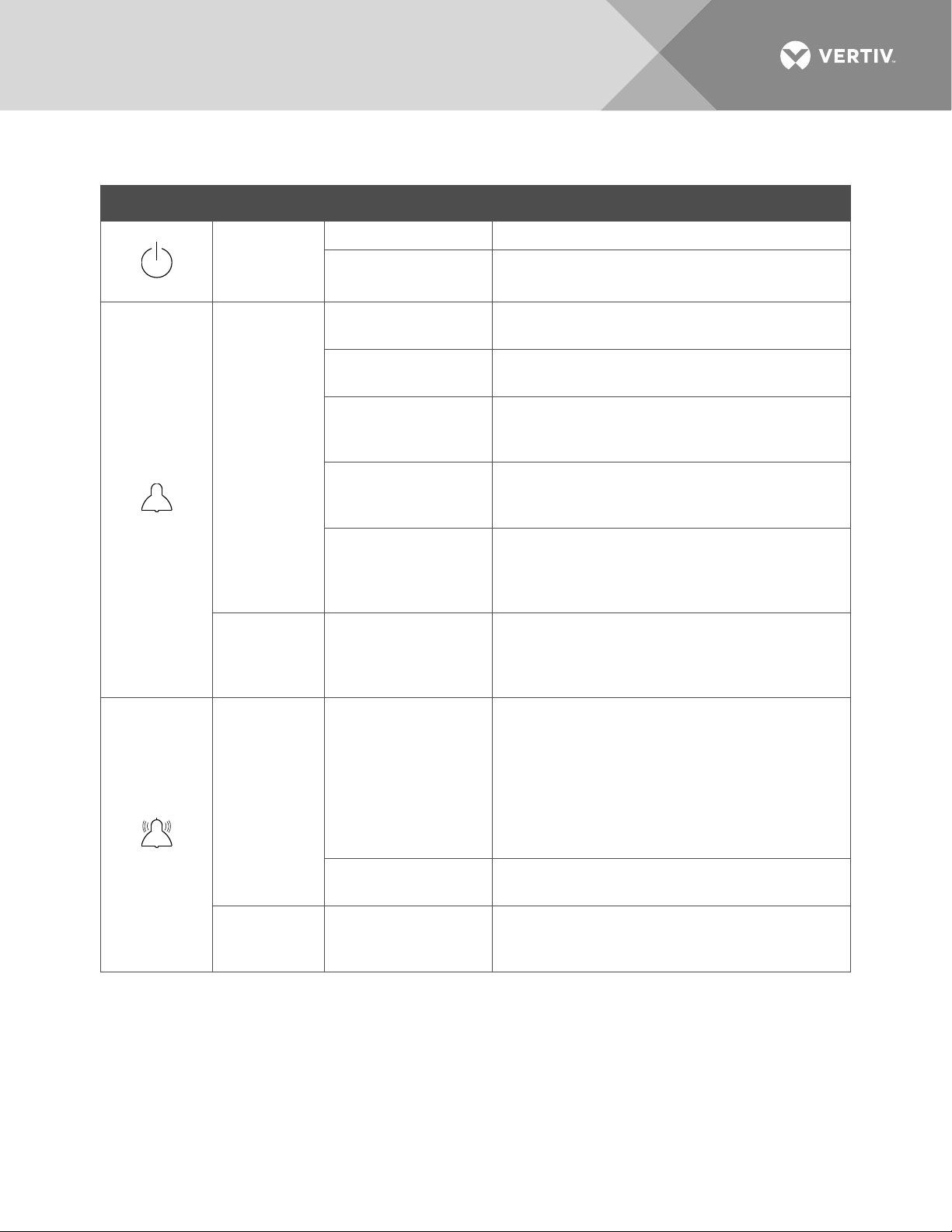
The fault indicators that can be displayed by the rectifier are as follows. Refer to Table 3 for a list of possible
causes and corrective actions.
• Power Indicator (Green) OFF
• Protection Indicator (Yellow) ON
• Protection Indicator (Yellow) Flashing
• Alarm Indicator (Red) ON
• Alarm Indicator (Red) Flashing
Vertiv | NetSure Rectifier Module User Manual (UM1R483500e) | Rev. R
Page 27
27
PFC under/over
Rectifier not inserted
Rectifier in ECO
Severe load sharing
Rectifier addresses
Alarm
Table 3:
Rectifier Troubleshooting
Symptom Possible Cause(s) Suggested Action(s)
Power
Indicator
(Green) Off
Protection
Indicator
No input voltage. Make sure there is input voltage.
Internal input fuse
open.
AC input under/over
voltage.
voltage.
Moderate load sharing
imbalance.
Replace the rectifier.
Correct the AC input voltage to within the
acceptable range.
Replace the rectifier.
Check if the rectifier is properly seated in the
shelf. If this does not correct the fault, replace
the rectifier.
(Yellow) On
completely.
Standby Mode when
ECO Mode is active in
into the slot
Remove and properly insert the rectifier.
--
controller.
Protection
Indicator
(Yellow)
Flashing
Alarm
Indicator
(Red) On
Indicator
(Red) Flashing
Loss of
communication with
controller (the rectifier
can provide power).
imbalance.
Rectifier output
disabled for any
reason, including
overvoltage shutdown
and internal output
fuse open.
contradictory.
Fan not operating
(rectifier shuts down).
Check the communication cables.
Remove and properly insert the rectifier.
Turn AC power to the rectifier off or remove the
rectifier, wait 30 seconds or more (until the LEDs
on the rectifier extinguish), then turn the AC
power to the rectifier on or re-insert the rectifier.
If rectifier fails to start, shuts down again, or load
sharing imbalance persists; replace the rectifier.
Replace the rectifier.
Replace the fan.
Vertiv | NetSure Rectifier Module User Manual (UM1R483500e) | Rev. R
Page 28

28
Replacement Procedures
Rectifier Replacement
The rectifier is hot swappable. It can be removed and installed with the system operating.
NOTE!
Each rectifier locks into a module mounting shelf by means of a latch located on the bottom of
the module. The latch and rectifier handle are interactive. Pushing the handle up into the module’s front
panel causes the latch to extend to the locking position; pulling the handle down out from the module’s
front panel causes the latch to retract. See
Figure 16
.
DANGER! Take care when removing a rectifier that was in operation, as rectifier surfaces could be very
hot.
WARNING! To prevent damage to the latching mechanism, ensure the handle is in the open position
when installing or removing a module. NEVER hold the handle in the closed position when installing a
module into a shelf.
Procedure
NOTE!
Refer to
Figure 16
as this procedure is performed.
1. Performing this procedure may activate external alarms. Do one of the following. If possible, disable
these alarms. If these alarms cannot be easily disabled, notify the appropriate personnel to disregard
any alarms associated with this system while this procedure is performed.
2. On the rectifier to be removed, click the rectifier’s handle in order to pop it forward out of the rectifier's
front panel. This will retract the latch mechanism located on the underside of the rectifier and thus
unlock the rectifier from the shelf. Refer to Figure 16 for latch mechanism illustration.
3. Slide the rectifier out by pulling forward.
4. Place the replacement rectifier into the mounting slot without sliding it in completely.
5. On the replacement rectifier, click the rectifier’s handle in order to pop it forward out of the rectifier's
front panel (this will also retract the latch mechanism located on the underside of the rectifier).
6. Push the rectifier completely into the shelf.
7. Push the handle into the front panel of the rectifier. This locks the rectifier securely to the shelf.
8. Certain functions (i.e. rectifier current limit, rectifier addressing) may require adjustment when adding or
replacing a rectifier Module. Refer to the Power System documentation for instructions.
9. After the rectifiers are physically installed in the mounting shelf(s), they are ready for operation
immediately after power is supplied to them. Verify that the rectifiers are operating normally.
10. Enable the external alarms, or notify appropriate personnel that this procedure is finished.
11. Ensure that there are no local or remote alarms active on the system.
Vertiv | NetSure Rectifier Module User Manual (UM1R483500e) | Rev. R
Page 29

29
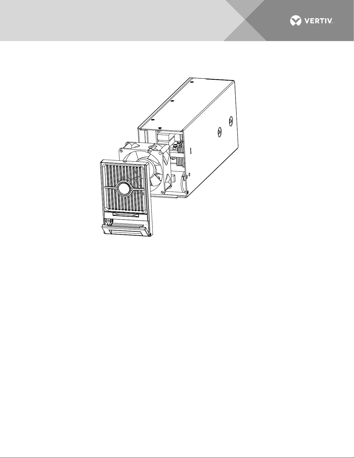
Rectifier Fan Replacement
Each rectifier uses a fan (P/N 32010086 for 1R483200 rectifier module. P/N 32010109 for 1R483200e,
1R483500e, and 1R484000e rectifier module) for cooling. If fan replacement should become necessary,
perform the following procedure.
CAUTION! In a system with NO redundant rectifier, battery must have sufficient reserve to power the
load(s) while the rectifier is removed for fan replacement.
NOTE!
When performing any step in this procedure that requires removal of existing hardware, retain all
hardware for use in subsequent steps.
Procedure
NOTE!
Refer to
Figure 17
as this procedure is performed.
1. Performing this procedure may activate external alarms. Do one of the following. If possible, disable
these alarms. If these alarms cannot be easily disabled, notify the appropriate personnel to disregard
any alarms associated with this system while this procedure is performed.
2. Remove the rectifier from the shelf. Refer to a previous procedure for step-by-step instructions.
3. Place the rectifier on a static-safe work surface. Connect an approved grounding strap to your wrist for
the remainder of this procedure.
4. On this rectifier, loosen the three (3) screws on the rectifier front cover and remove the cover.
5. For proper orientation of the new fan, observe the location of the fan wires and the air flow arrows on the
old fan.
6. Unplug the power cable of the old fan and remove the fan.
7. Plug the power cable of the new fan and place the new fan in the space vacated by the old fan. Ensure
the fan wires and air flow arrows match the orientation of the old fan.
8. Position the rectifier front cover back into place and secure with the screws previously removed.
9. Replace the rectifier into the shelf. Refer to the previous procedure for step-by-step instructions.
10. When the fans start, check to ensure that each is providing front-to-back airflow. If air direction is
wrong, immediately remove the rectifier from the shelf. Repeat previous steps to check fan orientation,
and correct as necessary. Reinstall the rectifier and again check for proper airflow.
11. Enable the external alarms, or notify appropriate personnel that this procedure is finished.
12. Ensure that there are no local or remote alarms active on the system.
Vertiv | NetSure Rectifier Module User Manual (UM1R483500e) | Rev. R
Page 30
30
Figure 17:
Rectifier Fan Replacement
Vertiv | NetSure Rectifier Module User Manual (UM1R483500e) | Rev. R
Page 31

31
This page is intentionally blank.
Vertiv | NetSure Rectifier Module User Manual (UM1R483500e) | Rev. R
Page 32

VertivCo.com | Vertiv Headquarters, 1050 Dearborn Drive, Columbus, OH, 43085, USA
UM1R483500e (RR 09/18)
 Loading...