

Page 1

Liebert® STS2
User Manual—100-1000A, 50/60Hz
™
Page 2

Page 3

TABLE OF CONTENTS
IMPORTANT SAFETY INSTRUCTIONS . . . . . . . . . . . . . . . . . . . . . . . . . . . . . . . . . . . . . . . . . . . . . . . .1
SAVE THESE INSTRUCTIONS . . . . . . . . . . . . . . . . . . . . . . . . . . . . . . . . . . . . . . . . . . . . . . . . . . . . . . . . 1
OVERVIEW OF MANUAL . . . . . . . . . . . . . . . . . . . . . . . . . . . . . . . . . . . . . . . . . . . . . . . . . . . . . . . . . . . . 2
1.0 SAFETY PRECAUTIONS. . . . . . . . . . . . . . . . . . . . . . . . . . . . . . . . . . . . . . . . . . . . . . . . . . . . . . . 3
2.0 UNPACKING AND INSPECTIONS . . . . . . . . . . . . . . . . . . . . . . . . . . . . . . . . . . . . . . . . . . . . . . 4
2.1 External Inspections . . . . . . . . . . . . . . . . . . . . . . . . . . . . . . . . . . . . . . . . . . . . . . . . . . . . . . . . . . . . . . . . . . . . . . . . . . . . . 4
2.2 Unloading and Handling. . . . . . . . . . . . . . . . . . . . . . . . . . . . . . . . . . . . . . . . . . . . . . . . . . . . . . . . . . . . . . . . . . . . . . . . . . 4
2.2.1 Handling Considerations . . . . . . . . . . . . . . . . . . . . . . . . . . . . . . . . . . . . . . . . . . . . . . . . . . . . . . . . . . . . . . . . . . . . . . . . . . 5
2.2.2 Unit Preparation . . . . . . . . . . . . . . . . . . . . . . . . . . . . . . . . . . . . . . . . . . . . . . . . . . . . . . . . . . . . . . . . . . . . . . . . . . . . . . . . . . 5
2.3 Internal Inspections . . . . . . . . . . . . . . . . . . . . . . . . . . . . . . . . . . . . . . . . . . . . . . . . . . . . . . . . . . . . . . . . . . . . . . . . . . . . . . .5
3.0 LOCATION CONSIDERATIONS . . . . . . . . . . . . . . . . . . . . . . . . . . . . . . . . . . . . . . . . . . . . . . . . 6
3.1 Recommended Minimum Service Clearances. . . . . . . . . . . . . . . . . . . . . . . . . . . . . . . . . . . . . . . . . . . . . . . . . . . . . . 6
3.2 Heat Output . . . . . . . . . . . . . . . . . . . . . . . . . . . . . . . . . . . . . . . . . . . . . . . . . . . . . . . . . . . . . . . . . . . . . . . . . . . . . . . . . . . . . 6
3.3 Operating Environment . . . . . . . . . . . . . . . . . . . . . . . . . . . . . . . . . . . . . . . . . . . . . . . . . . . . . . . . . . . . . . . . . . . . . . . . . . 6
3.4 Altitude . . . . . . . . . . . . . . . . . . . . . . . . . . . . . . . . . . . . . . . . . . . . . . . . . . . . . . . . . . . . . . . . . . . . . . . . . . . . . . . . . . . . . . . . . .7
4.0 LOCATING THE LIEBERT STS2 . . . . . . . . . . . . . . . . . . . . . . . . . . . . . . . . . . . . . . . . . . . . . . . . 8
4.1 Leveling and Anchoring the Unit to the Floor. . . . . . . . . . . . . . . . . . . . . . . . . . . . . . . . . . . . . . . . . . . . . . . . . . . . . . .8
4.2 Leveling of the Static Switch Without Anchoring . . . . . . . . . . . . . . . . . . . . . . . . . . . . . . . . . . . . . . . . . . . . . . . . . . .8
4.3 Leveling and Anchoring the Static Switch Using Floor Stand. . . . . . . . . . . . . . . . . . . . . . . . . . . . . . . . . . . . . . . .8
5.0 POWER AND CONTROL WIRING . . . . . . . . . . . . . . . . . . . . . . . . . . . . . . . . . . . . . . . . . . . . . . . 9
5.1 Input And Output Power Connections . . . . . . . . . . . . . . . . . . . . . . . . . . . . . . . . . . . . . . . . . . . . . . . . . . . . . . . . . . . . 9
5.1.1 Grounding . . . . . . . . . . . . . . . . . . . . . . . . . . . . . . . . . . . . . . . . . . . . . . . . . . . . . . . . . . . . . . . . . . . . . . . . . . . . . . . . . . . . . . . . 9
5.2 System Grounding . . . . . . . . . . . . . . . . . . . . . . . . . . . . . . . . . . . . . . . . . . . . . . . . . . . . . . . . . . . . . . . . . . . . . . . . . . . . . . .10
5.3 Control Wiring Connections . . . . . . . . . . . . . . . . . . . . . . . . . . . . . . . . . . . . . . . . . . . . . . . . . . . . . . . . . . . . . . . . . . . . . .12
5.4 Power Supply . . . . . . . . . . . . . . . . . . . . . . . . . . . . . . . . . . . . . . . . . . . . . . . . . . . . . . . . . . . . . . . . . . . . . . . . . . . . . . . . . . . .12
6.0 OPTIONS . . . . . . . . . . . . . . . . . . . . . . . . . . . . . . . . . . . . . . . . . . . . . . . . . . . . . . . . . . . . . . . . . . . .13
6.1 Programmable Relay Board. . . . . . . . . . . . . . . . . . . . . . . . . . . . . . . . . . . . . . . . . . . . . . . . . . . . . . . . . . . . . . . . . . . . . . .13
6.2 Optimized Transfer . . . . . . . . . . . . . . . . . . . . . . . . . . . . . . . . . . . . . . . . . . . . . . . . . . . . . . . . . . . . . . . . . . . . . . . . . . . . . .13
6.3 Distribution Cabinet With I-Line Panelboard—100-600A Units Only . . . . . . . . . . . . . . . . . . . . . . . . . . . . . . .13
6.4 Input Contact Isolator Board . . . . . . . . . . . . . . . . . . . . . . . . . . . . . . . . . . . . . . . . . . . . . . . . . . . . . . . . . . . . . . . . . . . . .13
6.5 Comms Board. . . . . . . . . . . . . . . . . . . . . . . . . . . . . . . . . . . . . . . . . . . . . . . . . . . . . . . . . . . . . . . . . . . . . . . . . . . . . . . . . . . .14
6.6 Liebert IntelliSlot™ SNMP/Web/Modbus 485 Card . . . . . . . . . . . . . . . . . . . . . . . . . . . . . . . . . . . . . . . . . . . . . . . . .14
6.7 LED Display . . . . . . . . . . . . . . . . . . . . . . . . . . . . . . . . . . . . . . . . . . . . . . . . . . . . . . . . . . . . . . . . . . . . . . . . . . . . . . . . . . . . .14
6.8 Remote Source Selection Wiring. . . . . . . . . . . . . . . . . . . . . . . . . . . . . . . . . . . . . . . . . . . . . . . . . . . . . . . . . . . . . . . . . .15
6.9 Key Lockout Switch . . . . . . . . . . . . . . . . . . . . . . . . . . . . . . . . . . . . . . . . . . . . . . . . . . . . . . . . . . . . . . . . . . . . . . . . . . . . . .15
6.10 Redundant Output Breaker. . . . . . . . . . . . . . . . . . . . . . . . . . . . . . . . . . . . . . . . . . . . . . . . . . . . . . . . . . . . . . . . . . . . . . . 15
6.11 Transfer Inhibit . . . . . . . . . . . . . . . . . . . . . . . . . . . . . . . . . . . . . . . . . . . . . . . . . . . . . . . . . . . . . . . . . . . . . . . . . . . . . . . . . .15
6.12 Input Junction Box Installation—Optional. . . . . . . . . . . . . . . . . . . . . . . . . . . . . . . . . . . . . . . . . . . . . . . . . . . . . . . . .16
6.13 Seismic Floor Anchors . . . . . . . . . . . . . . . . . . . . . . . . . . . . . . . . . . . . . . . . . . . . . . . . . . . . . . . . . . . . . . . . . . . . . . . . . . .16
Vertiv™ | Liebert® STS2™ 100-1000A, 50/60Hz User Manual | Rev. 12 | 11/2017 i
Page 4

6.14 Seismic Floor Stand . . . . . . . . . . . . . . . . . . . . . . . . . . . . . . . . . . . . . . . . . . . . . . . . . . . . . . . . . . . . . . . . . . . . . . . . . . . . . .16
7.0 INSTALLATION DRAWINGS . . . . . . . . . . . . . . . . . . . . . . . . . . . . . . . . . . . . . . . . . . . . . . . . . . .17
8.0 INTRODUCTION TO LIEBERT STS2 OPERATIONS . . . . . . . . . . . . . . . . . . . . . . . . . . . . . . 54
8.1 System Description . . . . . . . . . . . . . . . . . . . . . . . . . . . . . . . . . . . . . . . . . . . . . . . . . . . . . . . . . . . . . . . . . . . . . . . . . . . . . 54
8.1.1 Redundancy . . . . . . . . . . . . . . . . . . . . . . . . . . . . . . . . . . . . . . . . . . . . . . . . . . . . . . . . . . . . . . . . . . . . . . . . . . . . . . . . . . . . . 54
8.1.2 Reliability and Agency Requirements . . . . . . . . . . . . . . . . . . . . . . . . . . . . . . . . . . . . . . . . . . . . . . . . . . . . . . . . . . . . . 55
8.1.3 Factory Backup and Service Assistance . . . . . . . . . . . . . . . . . . . . . . . . . . . . . . . . . . . . . . . . . . . . . . . . . . . . . . . . . . 55
8.2 Modes of Operation . . . . . . . . . . . . . . . . . . . . . . . . . . . . . . . . . . . . . . . . . . . . . . . . . . . . . . . . . . . . . . . . . . . . . . . . . . . . . 55
8.2.1 Normal (Preferred Source) . . . . . . . . . . . . . . . . . . . . . . . . . . . . . . . . . . . . . . . . . . . . . . . . . . . . . . . . . . . . . . . . . . . . . . . 55
8.2.2 Transfer . . . . . . . . . . . . . . . . . . . . . . . . . . . . . . . . . . . . . . . . . . . . . . . . . . . . . . . . . . . . . . . . . . . . . . . . . . . . . . . . . . . . . . . . . 55
8.2.3 Transfer Inhibit . . . . . . . . . . . . . . . . . . . . . . . . . . . . . . . . . . . . . . . . . . . . . . . . . . . . . . . . . . . . . . . . . . . . . . . . . . . . . . . . . . 55
8.2.4 Bypass . . . . . . . . . . . . . . . . . . . . . . . . . . . . . . . . . . . . . . . . . . . . . . . . . . . . . . . . . . . . . . . . . . . . . . . . . . . . . . . . . . . . . . . . . . 56
8.3 Operator Controls. . . . . . . . . . . . . . . . . . . . . . . . . . . . . . . . . . . . . . . . . . . . . . . . . . . . . . . . . . . . . . . . . . . . . . . . . . . . . . . 56
9.0 THEORY OF OPERATION. . . . . . . . . . . . . . . . . . . . . . . . . . . . . . . . . . . . . . . . . . . . . . . . . . . . . 57
9.1 General Description . . . . . . . . . . . . . . . . . . . . . . . . . . . . . . . . . . . . . . . . . . . . . . . . . . . . . . . . . . . . . . . . . . . . . . . . . . . . . 57
9.1.1 Liebert STS2 Static Transfer Switch . . . . . . . . . . . . . . . . . . . . . . . . . . . . . . . . . . . . . . . . . . . . . . . . . . . . . . . . . . . . . . 57
9.1.2 Source Transfer. . . . . . . . . . . . . . . . . . . . . . . . . . . . . . . . . . . . . . . . . . . . . . . . . . . . . . . . . . . . . . . . . . . . . . . . . . . . . . . . . . 57
9.1.3 Automatic Transfer/Retransfer . . . . . . . . . . . . . . . . . . . . . . . . . . . . . . . . . . . . . . . . . . . . . . . . . . . . . . . . . . . . . . . . . . . 57
9.1.4 Emergency Transfer . . . . . . . . . . . . . . . . . . . . . . . . . . . . . . . . . . . . . . . . . . . . . . . . . . . . . . . . . . . . . . . . . . . . . . . . . . . . . 58
9.1.5 Load Current Transfer Inhibit. . . . . . . . . . . . . . . . . . . . . . . . . . . . . . . . . . . . . . . . . . . . . . . . . . . . . . . . . . . . . . . . . . . . . 58
9.1.6 SCR Failure . . . . . . . . . . . . . . . . . . . . . . . . . . . . . . . . . . . . . . . . . . . . . . . . . . . . . . . . . . . . . . . . . . . . . . . . . . . . . . . . . . . . . . 58
9.1.7 On/Off Sequence . . . . . . . . . . . . . . . . . . . . . . . . . . . . . . . . . . . . . . . . . . . . . . . . . . . . . . . . . . . . . . . . . . . . . . . . . . . . . . . . 58
9.2 Detailed Component Description . . . . . . . . . . . . . . . . . . . . . . . . . . . . . . . . . . . . . . . . . . . . . . . . . . . . . . . . . . . . . . . . 59
9.2.1 Controls. . . . . . . . . . . . . . . . . . . . . . . . . . . . . . . . . . . . . . . . . . . . . . . . . . . . . . . . . . . . . . . . . . . . . . . . . . . . . . . . . . . . . . . . . 59
9.2.2 Circuit Breakers . . . . . . . . . . . . . . . . . . . . . . . . . . . . . . . . . . . . . . . . . . . . . . . . . . . . . . . . . . . . . . . . . . . . . . . . . . . . . . . . . 59
9.2.3 SCR’s. . . . . . . . . . . . . . . . . . . . . . . . . . . . . . . . . . . . . . . . . . . . . . . . . . . . . . . . . . . . . . . . . . . . . . . . . . . . . . . . . . . . . . . . . . . . 60
9.2.4 Logic Modules . . . . . . . . . . . . . . . . . . . . . . . . . . . . . . . . . . . . . . . . . . . . . . . . . . . . . . . . . . . . . . . . . . . . . . . . . . . . . . . . . . . 60
9.2.5 Audible Alarm . . . . . . . . . . . . . . . . . . . . . . . . . . . . . . . . . . . . . . . . . . . . . . . . . . . . . . . . . . . . . . . . . . . . . . . . . . . . . . . . . . . 60
9.2.6 RS-232 Port . . . . . . . . . . . . . . . . . . . . . . . . . . . . . . . . . . . . . . . . . . . . . . . . . . . . . . . . . . . . . . . . . . . . . . . . . . . . . . . . . . . . . 60
10.0 OPERATING INSTRUCTIONS FOR THE TOUCHSCREEN INTERFACE. . . . . . . . . . . . . 61
10.1 Normal System Startup . . . . . . . . . . . . . . . . . . . . . . . . . . . . . . . . . . . . . . . . . . . . . . . . . . . . . . . . . . . . . . . . . . . . . . . . . 62
10.2 Manual Transfer / Preferred Source Selection . . . . . . . . . . . . . . . . . . . . . . . . . . . . . . . . . . . . . . . . . . . . . . . . . . . . 62
10.3 Enabling Remote Source Selection. . . . . . . . . . . . . . . . . . . . . . . . . . . . . . . . . . . . . . . . . . . . . . . . . . . . . . . . . . . . . . . 64
10.4 Maintenance Bypass . . . . . . . . . . . . . . . . . . . . . . . . . . . . . . . . . . . . . . . . . . . . . . . . . . . . . . . . . . . . . . . . . . . . . . . . . . . . 64
10.4.1 Bypass Procedures for Source 1 . . . . . . . . . . . . . . . . . . . . . . . . . . . . . . . . . . . . . . . . . . . . . . . . . . . . . . . . . . . . . . . . . . 66
10.4.2 Bypass Procedures for Source 2 . . . . . . . . . . . . . . . . . . . . . . . . . . . . . . . . . . . . . . . . . . . . . . . . . . . . . . . . . . . . . . . . . . 67
10.5 Normal System Shutdown . . . . . . . . . . . . . . . . . . . . . . . . . . . . . . . . . . . . . . . . . . . . . . . . . . . . . . . . . . . . . . . . . . . . . . . 67
10.5.1 Shutdown in Static Transfer Switch Mode. . . . . . . . . . . . . . . . . . . . . . . . . . . . . . . . . . . . . . . . . . . . . . . . . . . . . . . . . 67
10.5.2 Shutdown in Maintenance Bypass Mode . . . . . . . . . . . . . . . . . . . . . . . . . . . . . . . . . . . . . . . . . . . . . . . . . . . . . . . . . . 67
11.0 ALARM AND FAULTS . . . . . . . . . . . . . . . . . . . . . . . . . . . . . . . . . . . . . . . . . . . . . . . . . . . . . . . . 68
11.1 Event Mask . . . . . . . . . . . . . . . . . . . . . . . . . . . . . . . . . . . . . . . . . . . . . . . . . . . . . . . . . . . . . . . . . . . . . . . . . . . . . . . . . . . . . 68
11.2 Event and History Logs . . . . . . . . . . . . . . . . . . . . . . . . . . . . . . . . . . . . . . . . . . . . . . . . . . . . . . . . . . . . . . . . . . . . . . . . . 68
11.2.1 Event Log . . . . . . . . . . . . . . . . . . . . . . . . . . . . . . . . . . . . . . . . . . . . . . . . . . . . . . . . . . . . . . . . . . . . . . . . . . . . . . . . . . . . . . . 69
11.2.2 History Log. . . . . . . . . . . . . . . . . . . . . . . . . . . . . . . . . . . . . . . . . . . . . . . . . . . . . . . . . . . . . . . . . . . . . . . . . . . . . . . . . . . . . . 69
11.3 Alarm Notes . . . . . . . . . . . . . . . . . . . . . . . . . . . . . . . . . . . . . . . . . . . . . . . . . . . . . . . . . . . . . . . . . . . . . . . . . . . . . . . . . . . . 70
Vertiv™ | Liebert® STS2™ 100-1000A, 50/60Hz User Manual | Rev. 12 | 11/2017 ii
Page 5

11.4 List of Messages . . . . . . . . . . . . . . . . . . . . . . . . . . . . . . . . . . . . . . . . . . . . . . . . . . . . . . . . . . . . . . . . . . . . . . . . . . . . . . . . 70
12.0 COMMUNICATION INTERFACES. . . . . . . . . . . . . . . . . . . . . . . . . . . . . . . . . . . . . . . . . . . . . . 73
12.1 Using the RS-232 Port. . . . . . . . . . . . . . . . . . . . . . . . . . . . . . . . . . . . . . . . . . . . . . . . . . . . . . . . . . . . . . . . . . . . . . . . . . . 73
12.1.1 Connecting and Using a Terminal. . . . . . . . . . . . . . . . . . . . . . . . . . . . . . . . . . . . . . . . . . . . . . . . . . . . . . . . . . . . . . . . . 74
12.1.2 Configuring the Liebert STS2 via the Terminal . . . . . . . . . . . . . . . . . . . . . . . . . . . . . . . . . . . . . . . . . . . . . . . . . . . . 75
12.1.3 Setting Bitpacked Options with the Terminal. . . . . . . . . . . . . . . . . . . . . . . . . . . . . . . . . . . . . . . . . . . . . . . . . . . . . . 78
12.1.4 Setting Event Masks with the Terminal . . . . . . . . . . . . . . . . . . . . . . . . . . . . . . . . . . . . . . . . . . . . . . . . . . . . . . . . . . . 80
13.0 LIEBERT STS2 TOUCHSCREEN DISPLAY . . . . . . . . . . . . . . . . . . . . . . . . . . . . . . . . . . . . . . 82
13.1 Display Overview . . . . . . . . . . . . . . . . . . . . . . . . . . . . . . . . . . . . . . . . . . . . . . . . . . . . . . . . . . . . . . . . . . . . . . . . . . . . . . . 82
13.2 Menu Overview . . . . . . . . . . . . . . . . . . . . . . . . . . . . . . . . . . . . . . . . . . . . . . . . . . . . . . . . . . . . . . . . . . . . . . . . . . . . . . . . . 83
13.2.1 Security . . . . . . . . . . . . . . . . . . . . . . . . . . . . . . . . . . . . . . . . . . . . . . . . . . . . . . . . . . . . . . . . . . . . . . . . . . . . . . . . . . . . . . . . . 84
13.3 Mimic Display. . . . . . . . . . . . . . . . . . . . . . . . . . . . . . . . . . . . . . . . . . . . . . . . . . . . . . . . . . . . . . . . . . . . . . . . . . . . . . . . . . . 85
13.4 Event Controls . . . . . . . . . . . . . . . . . . . . . . . . . . . . . . . . . . . . . . . . . . . . . . . . . . . . . . . . . . . . . . . . . . . . . . . . . . . . . . . . . . 85
13.5 Event Display . . . . . . . . . . . . . . . . . . . . . . . . . . . . . . . . . . . . . . . . . . . . . . . . . . . . . . . . . . . . . . . . . . . . . . . . . . . . . . . . . . . 85
13.6 Menu Bar . . . . . . . . . . . . . . . . . . . . . . . . . . . . . . . . . . . . . . . . . . . . . . . . . . . . . . . . . . . . . . . . . . . . . . . . . . . . . . . . . . . . . . . 85
13.7 Configuration Menu . . . . . . . . . . . . . . . . . . . . . . . . . . . . . . . . . . . . . . . . . . . . . . . . . . . . . . . . . . . . . . . . . . . . . . . . . . . . . 85
13.7.1 System Ratings . . . . . . . . . . . . . . . . . . . . . . . . . . . . . . . . . . . . . . . . . . . . . . . . . . . . . . . . . . . . . . . . . . . . . . . . . . . . . . . . . . 85
13.7.2 Event Masks. . . . . . . . . . . . . . . . . . . . . . . . . . . . . . . . . . . . . . . . . . . . . . . . . . . . . . . . . . . . . . . . . . . . . . . . . . . . . . . . . . . . . 85
13.7.3 User Settings . . . . . . . . . . . . . . . . . . . . . . . . . . . . . . . . . . . . . . . . . . . . . . . . . . . . . . . . . . . . . . . . . . . . . . . . . . . . . . . . . . . . 86
13.7.4 System Settings . . . . . . . . . . . . . . . . . . . . . . . . . . . . . . . . . . . . . . . . . . . . . . . . . . . . . . . . . . . . . . . . . . . . . . . . . . . . . . . . . 90
13.8 Comm Options . . . . . . . . . . . . . . . . . . . . . . . . . . . . . . . . . . . . . . . . . . . . . . . . . . . . . . . . . . . . . . . . . . . . . . . . . . . . . . . . . . 90
13.8.1 Configuring the Input Contact Isolator Settings . . . . . . . . . . . . . . . . . . . . . . . . . . . . . . . . . . . . . . . . . . . . . . . . . . . .91
13.8.2 Configuring the Programmable Relay Board Settings . . . . . . . . . . . . . . . . . . . . . . . . . . . . . . . . . . . . . . . . . . . . . . 92
13.8.3 Configuring the Liebert IntelliSlot
13.8.4 Liebert SiteScan
13.8.5 Saving Your Communications Configurations . . . . . . . . . . . . . . . . . . . . . . . . . . . . . . . . . . . . . . . . . . . . . . . . . . . . . 94
®
Configuration . . . . . . . . . . . . . . . . . . . . . . . . . . . . . . . . . . . . . . . . . . . . . . . . . . . . . . . . . . . . . . . . . . 94
13.9 System Options . . . . . . . . . . . . . . . . . . . . . . . . . . . . . . . . . . . . . . . . . . . . . . . . . . . . . . . . . . . . . . . . . . . . . . . . . . . . . . . . . 94
13.10 System ID . . . . . . . . . . . . . . . . . . . . . . . . . . . . . . . . . . . . . . . . . . . . . . . . . . . . . . . . . . . . . . . . . . . . . . . . . . . . . . . . . . . . . . 95
13.11 Logs. . . . . . . . . . . . . . . . . . . . . . . . . . . . . . . . . . . . . . . . . . . . . . . . . . . . . . . . . . . . . . . . . . . . . . . . . . . . . . . . . . . . . . . . . . . . 96
13.11.1 Event Log . . . . . . . . . . . . . . . . . . . . . . . . . . . . . . . . . . . . . . . . . . . . . . . . . . . . . . . . . . . . . . . . . . . . . . . . . . . . . . . . . . . . . . . 96
13.11.2 History Log. . . . . . . . . . . . . . . . . . . . . . . . . . . . . . . . . . . . . . . . . . . . . . . . . . . . . . . . . . . . . . . . . . . . . . . . . . . . . . . . . . . . . . 96
13.12 Source Transfers. . . . . . . . . . . . . . . . . . . . . . . . . . . . . . . . . . . . . . . . . . . . . . . . . . . . . . . . . . . . . . . . . . . . . . . . . . . . . . . . 97
13.13 Startup Procedure . . . . . . . . . . . . . . . . . . . . . . . . . . . . . . . . . . . . . . . . . . . . . . . . . . . . . . . . . . . . . . . . . . . . . . . . . . . . . . 97
13.14 Bypass Procedure. . . . . . . . . . . . . . . . . . . . . . . . . . . . . . . . . . . . . . . . . . . . . . . . . . . . . . . . . . . . . . . . . . . . . . . . . . . . . . . 97
13.15 Help. . . . . . . . . . . . . . . . . . . . . . . . . . . . . . . . . . . . . . . . . . . . . . . . . . . . . . . . . . . . . . . . . . . . . . . . . . . . . . . . . . . . . . . . . . . . 97
13.16 Logo . . . . . . . . . . . . . . . . . . . . . . . . . . . . . . . . . . . . . . . . . . . . . . . . . . . . . . . . . . . . . . . . . . . . . . . . . . . . . . . . . . . . . . . . . . . 97
13.17 Cleaning the LCD Touchscreen . . . . . . . . . . . . . . . . . . . . . . . . . . . . . . . . . . . . . . . . . . . . . . . . . . . . . . . . . . . . . . . . . . 97
™
SNMP/Web/Modbus 485 Card . . . . . . . . . . . . . . . . . . . . . . . . . . . . . . . . . 93
14.0 OPERATING THE LIEBERT STS2 LED DISPLAY . . . . . . . . . . . . . . . . . . . . . . . . . . . . . . . . 98
14.1 LED’s and Buttons and Key Lockout Switch . . . . . . . . . . . . . . . . . . . . . . . . . . . . . . . . . . . . . . . . . . . . . . . . . . . . . . 98
14.1.1 Front Panel Controls . . . . . . . . . . . . . . . . . . . . . . . . . . . . . . . . . . . . . . . . . . . . . . . . . . . . . . . . . . . . . . . . . . . . . . . . . . . . . 98
14.1.2 LED and Push Button Description . . . . . . . . . . . . . . . . . . . . . . . . . . . . . . . . . . . . . . . . . . . . . . . . . . . . . . . . . . . . . . . 100
14.1.3 Event Controls. . . . . . . . . . . . . . . . . . . . . . . . . . . . . . . . . . . . . . . . . . . . . . . . . . . . . . . . . . . . . . . . . . . . . . . . . . . . . . . . . . 100
14.1.4 Key Lockout Switch . . . . . . . . . . . . . . . . . . . . . . . . . . . . . . . . . . . . . . . . . . . . . . . . . . . . . . . . . . . . . . . . . . . . . . . . . . . . . .101
Vertiv™ | Liebert® STS2™ 100-1000A, 50/60Hz User Manual | Rev. 12 | 11/2017 iii
Page 6

14.2 Operations. . . . . . . . . . . . . . . . . . . . . . . . . . . . . . . . . . . . . . . . . . . . . . . . . . . . . . . . . . . . . . . . . . . . . . . . . . . . . . . . . . . . . . 101
14.2.1 Normal System Startup . . . . . . . . . . . . . . . . . . . . . . . . . . . . . . . . . . . . . . . . . . . . . . . . . . . . . . . . . . . . . . . . . . . . . . . . . .101
14.2.2 Manual Transfer / Preferred Source Selection . . . . . . . . . . . . . . . . . . . . . . . . . . . . . . . . . . . . . . . . . . . . . . . . . . . . 102
14.2.3 Maintenance Bypass . . . . . . . . . . . . . . . . . . . . . . . . . . . . . . . . . . . . . . . . . . . . . . . . . . . . . . . . . . . . . . . . . . . . . . . . . . . . 103
14.2.4 Normal System Shutdown . . . . . . . . . . . . . . . . . . . . . . . . . . . . . . . . . . . . . . . . . . . . . . . . . . . . . . . . . . . . . . . . . . . . . . . 105
15.0 SPECIFICATIONS. . . . . . . . . . . . . . . . . . . . . . . . . . . . . . . . . . . . . . . . . . . . . . . . . . . . . . . . . . . 106
15.1 System Configuration . . . . . . . . . . . . . . . . . . . . . . . . . . . . . . . . . . . . . . . . . . . . . . . . . . . . . . . . . . . . . . . . . . . . . . . . . . 106
15.1.1 Frequency . . . . . . . . . . . . . . . . . . . . . . . . . . . . . . . . . . . . . . . . . . . . . . . . . . . . . . . . . . . . . . . . . . . . . . . . . . . . . . . . . . . . . . 106
15.1.2 Input/Output Voltage . . . . . . . . . . . . . . . . . . . . . . . . . . . . . . . . . . . . . . . . . . . . . . . . . . . . . . . . . . . . . . . . . . . . . . . . . . . 106
15.1.3 System Current Ratings. . . . . . . . . . . . . . . . . . . . . . . . . . . . . . . . . . . . . . . . . . . . . . . . . . . . . . . . . . . . . . . . . . . . . . . . . 106
15.1.4 Grounding . . . . . . . . . . . . . . . . . . . . . . . . . . . . . . . . . . . . . . . . . . . . . . . . . . . . . . . . . . . . . . . . . . . . . . . . . . . . . . . . . . . . . . 107
15.1.5 Electrical Requirements . . . . . . . . . . . . . . . . . . . . . . . . . . . . . . . . . . . . . . . . . . . . . . . . . . . . . . . . . . . . . . . . . . . . . . . . . 107
15.1.6 Input Surge Suppression . . . . . . . . . . . . . . . . . . . . . . . . . . . . . . . . . . . . . . . . . . . . . . . . . . . . . . . . . . . . . . . . . . . . . . . . 107
15.1.7 Response Time . . . . . . . . . . . . . . . . . . . . . . . . . . . . . . . . . . . . . . . . . . . . . . . . . . . . . . . . . . . . . . . . . . . . . . . . . . . . . . . . . 107
15.1.8 Environmental Requirements . . . . . . . . . . . . . . . . . . . . . . . . . . . . . . . . . . . . . . . . . . . . . . . . . . . . . . . . . . . . . . . . . . . . 107
15.2 System Components . . . . . . . . . . . . . . . . . . . . . . . . . . . . . . . . . . . . . . . . . . . . . . . . . . . . . . . . . . . . . . . . . . . . . . . . . . . 108
15.2.1 Frame and Enclosure. . . . . . . . . . . . . . . . . . . . . . . . . . . . . . . . . . . . . . . . . . . . . . . . . . . . . . . . . . . . . . . . . . . . . . . . . . . . 108
15.2.2 Casters, Leveling and Seismic Anchoring . . . . . . . . . . . . . . . . . . . . . . . . . . . . . . . . . . . . . . . . . . . . . . . . . . . . . . . . 108
15.2.3 Cooling . . . . . . . . . . . . . . . . . . . . . . . . . . . . . . . . . . . . . . . . . . . . . . . . . . . . . . . . . . . . . . . . . . . . . . . . . . . . . . . . . . . . . . . . . 108
15.2.4 Access . . . . . . . . . . . . . . . . . . . . . . . . . . . . . . . . . . . . . . . . . . . . . . . . . . . . . . . . . . . . . . . . . . . . . . . . . . . . . . . . . . . . . . . . . 109
15.2.5 Circuit Breakers . . . . . . . . . . . . . . . . . . . . . . . . . . . . . . . . . . . . . . . . . . . . . . . . . . . . . . . . . . . . . . . . . . . . . . . . . . . . . . . . 109
15.2.6 Cable Entrance . . . . . . . . . . . . . . . . . . . . . . . . . . . . . . . . . . . . . . . . . . . . . . . . . . . . . . . . . . . . . . . . . . . . . . . . . . . . . . . . . 109
15.2.7 Doors . . . . . . . . . . . . . . . . . . . . . . . . . . . . . . . . . . . . . . . . . . . . . . . . . . . . . . . . . . . . . . . . . . . . . . . . . . . . . . . . . . . . . . . . . . 109
15.2.8 Color Graphical Display or LED Display . . . . . . . . . . . . . . . . . . . . . . . . . . . . . . . . . . . . . . . . . . . . . . . . . . . . . . . . . . 109
15.2.9 RS-232 Port . . . . . . . . . . . . . . . . . . . . . . . . . . . . . . . . . . . . . . . . . . . . . . . . . . . . . . . . . . . . . . . . . . . . . . . . . . . . . . . . . . . . .110
15.2.10 Terminal Port Connections . . . . . . . . . . . . . . . . . . . . . . . . . . . . . . . . . . . . . . . . . . . . . . . . . . . . . . . . . . . . . . . . . . . . . . .110
15.2.11 RS-232 Interface Parameters . . . . . . . . . . . . . . . . . . . . . . . . . . . . . . . . . . . . . . . . . . . . . . . . . . . . . . . . . . . . . . . . . . . . .110
15.2.12 Maintenance Bypass . . . . . . . . . . . . . . . . . . . . . . . . . . . . . . . . . . . . . . . . . . . . . . . . . . . . . . . . . . . . . . . . . . . . . . . . . . . . . 111
15.2.13 Fuseless Design . . . . . . . . . . . . . . . . . . . . . . . . . . . . . . . . . . . . . . . . . . . . . . . . . . . . . . . . . . . . . . . . . . . . . . . . . . . . . . . . . 111
15.2.14 Options . . . . . . . . . . . . . . . . . . . . . . . . . . . . . . . . . . . . . . . . . . . . . . . . . . . . . . . . . . . . . . . . . . . . . . . . . . . . . . . . . . . . . . . . . 111
16.0 EVENT MESSAGE HELP TEXT. . . . . . . . . . . . . . . . . . . . . . . . . . . . . . . . . . . . . . . . . . . . . . . . 112
17.0 MAINTENANCE . . . . . . . . . . . . . . . . . . . . . . . . . . . . . . . . . . . . . . . . . . . . . . . . . . . . . . . . . . . . 130
17.1 Proper Tightening of Nuts and Bolts . . . . . . . . . . . . . . . . . . . . . . . . . . . . . . . . . . . . . . . . . . . . . . . . . . . . . . . . . . . . 130
17.2 Testing the Liebert STS2 . . . . . . . . . . . . . . . . . . . . . . . . . . . . . . . . . . . . . . . . . . . . . . . . . . . . . . . . . . . . . . . . . . . . . . . 130
17.3 Changing the Air Filter . . . . . . . . . . . . . . . . . . . . . . . . . . . . . . . . . . . . . . . . . . . . . . . . . . . . . . . . . . . . . . . . . . . . . . . . . 130
APPENDIX A - SUPPORT INFORMATION . . . . . . . . . . . . . . . . . . . . . . . . . . . . . . . . . . . . . . . . . . A131
APPENDIX B - PROGRAMMABLE RELAY BOARD SETTINGS RECORD. . . . . . . . . . . . . . . . A132
APPENDIX C - INPUT CONTACT ISOLATOR SETTINGS RECORD . . . . . . . . . . . . . . . . . . . . A134
Vertiv™ | Liebert® STS2™ 100-1000A, 50/60Hz User Manual | Rev. 12 | 11/2017 iv
Page 7

FIGURES
Figure 1 Maximum ambient temperature for full load operation at higher altitudes . . . . . . . . . . . . . . . . . . . . . . .7
Figure 2 Typical static transfer switch one-line diagram . . . . . . . . . . . . . . . . . . . . . . . . . . . . . . . . . . . . . . . . . . . . . . . .10
Figure 3 Typical one-line diagram of two PDUs and a Liebert STS2 . . . . . . . . . . . . . . . . . . . . . . . . . . . . . . . . . . . . . 11
Figure 4 Outline drawing: 100 – 250 amp Liebert STS2 . . . . . . . . . . . . . . . . . . . . . . . . . . . . . . . . . . . . . . . . . . . . . . . . . 17
Figure 5 Outline drawing: 400 – 600 amp Liebert STS2 . . . . . . . . . . . . . . . . . . . . . . . . . . . . . . . . . . . . . . . . . . . . . . . .18
Figure 6 Outline drawing: 800 – 1000 amp Liebert STS2 . . . . . . . . . . . . . . . . . . . . . . . . . . . . . . . . . . . . . . . . . . . . . . .19
Figure 7 Outline drawing: 100 – 250amp Liebert STS2 with a key lockout switch option. . . . . . . . . . . . . . . . . 20
Figure 8 Outline drawing: 400 – 600 amp Liebert STS2 with a key lockout switch option . . . . . . . . . . . . . . . .21
Figure 9 Outline drawing: 800 – 1000 amp Liebert STS2 with the key lockout switch option . . . . . . . . . . . . 22
Figure 10 Seismic anchor drawing: 100 – 250 amp Liebert STS2 . . . . . . . . . . . . . . . . . . . . . . . . . . . . . . . . . . . . . . . . 23
Figure 11 Seismic anchor drawing: 400 – 600 amp Liebert STS2. . . . . . . . . . . . . . . . . . . . . . . . . . . . . . . . . . . . . . . . 24
Figure 12 Seismic anchor drawing: 800 – 1000 amp Liebert STS2. . . . . . . . . . . . . . . . . . . . . . . . . . . . . . . . . . . . . . . 25
Figure 13 Electrical field connections drawing: 100 – 250 amp Liebert STS2 with single output
breaker . . . . . . . . . . . . . . . . . . . . . . . . . . . . . . . . . . . . . . . . . . . . . . . . . . . . . . . . . . . . . . . . . . . . . . . . . . . . . . . . . . . . . 26
Figure 14 Electrical field connections drawing: 100 – 250 amp Liebert STS2 with dual output
breakers . . . . . . . . . . . . . . . . . . . . . . . . . . . . . . . . . . . . . . . . . . . . . . . . . . . . . . . . . . . . . . . . . . . . . . . . . . . . . . . . . . . . 27
Figure 15 Electrical field connections drawing: 400 – 600 amp Liebert STS2 with single output
breaker . . . . . . . . . . . . . . . . . . . . . . . . . . . . . . . . . . . . . . . . . . . . . . . . . . . . . . . . . . . . . . . . . . . . . . . . . . . . . . . . . . . . . 28
Figure 16 Electrical field connections drawing: 400 – 600 amp Liebert STS2 with dual output
breakers . . . . . . . . . . . . . . . . . . . . . . . . . . . . . . . . . . . . . . . . . . . . . . . . . . . . . . . . . . . . . . . . . . . . . . . . . . . . . . . . . . . . 29
Figure 17 Electrical field connections drawing: 800 – 1000 amp Liebert STS2 with single output
breaker . . . . . . . . . . . . . . . . . . . . . . . . . . . . . . . . . . . . . . . . . . . . . . . . . . . . . . . . . . . . . . . . . . . . . . . . . . . . . . . . . . . . . 30
Figure 18 Electrical field connections: 800 – 1000 amp Liebert STS2 with dual output breakers. . . . . . . . . . . 31
Figure 19 Control connection location diagram: 100 – 600 amp Liebert STS2. . . . . . . . . . . . . . . . . . . . . . . . . . . . 32
Figure 20 Control connection location diagram: 800 – 1000 amp Liebert STS2 . . . . . . . . . . . . . . . . . . . . . . . . . . 33
Figure 21 Control wiring for remote source selection option . . . . . . . . . . . . . . . . . . . . . . . . . . . . . . . . . . . . . . . . . . . . 34
Figure 22 Control wiring for the programmable relay board option . . . . . . . . . . . . . . . . . . . . . . . . . . . . . . . . . . . . . . 35
Figure 23 Control wiring for the input contact isolator board option. . . . . . . . . . . . . . . . . . . . . . . . . . . . . . . . . . . . . 36
Figure 24 Control wiring for Comms board . . . . . . . . . . . . . . . . . . . . . . . . . . . . . . . . . . . . . . . . . . . . . . . . . . . . . . . . . . . . . 37
Figure 25 Control wiring for the Liebert IntelliSlot SNMP/Web/Modbus 485 card . . . . . . . . . . . . . . . . . . . . . . . . 38
Figure 26 Control wiring for the RS-232 port . . . . . . . . . . . . . . . . . . . . . . . . . . . . . . . . . . . . . . . . . . . . . . . . . . . . . . . . . . . 39
Figure 27 Outline drawing for input junction box . . . . . . . . . . . . . . . . . . . . . . . . . . . . . . . . . . . . . . . . . . . . . . . . . . . . . . . 40
Figure 28 LED display . . . . . . . . . . . . . . . . . . . . . . . . . . . . . . . . . . . . . . . . . . . . . . . . . . . . . . . . . . . . . . . . . . . . . . . . . . . . . . . . . .41
Figure 29 Installation drawing, seismic floor stand 100-250A. . . . . . . . . . . . . . . . . . . . . . . . . . . . . . . . . . . . . . . . . . . . 42
Figure 30 Installation drawing, seismic floor stand 100-250A. . . . . . . . . . . . . . . . . . . . . . . . . . . . . . . . . . . . . . . . . . . . 43
Figure 31 Installation drawing, seismic floor stand 100-250A. . . . . . . . . . . . . . . . . . . . . . . . . . . . . . . . . . . . . . . . . . . . 44
Figure 32 Installation drawing, seismic floor stand 100-250A. . . . . . . . . . . . . . . . . . . . . . . . . . . . . . . . . . . . . . . . . . . . 45
Figure 33 Installation drawing, seismic floor stand 400-600A. . . . . . . . . . . . . . . . . . . . . . . . . . . . . . . . . . . . . . . . . . . 46
Figure 34 Installation drawing, seismic floor stand 400-600A. . . . . . . . . . . . . . . . . . . . . . . . . . . . . . . . . . . . . . . . . . . 47
Figure 35 Installation drawing, seismic floor stand 400-600A . . . . . . . . . . . . . . . . . . . . . . . . . . . . . . . . . . . . . . . . . . . 48
Figure 36 Installation drawing, seismic floor stand 400-600A . . . . . . . . . . . . . . . . . . . . . . . . . . . . . . . . . . . . . . . . . . . 49
Figure 37 Installation drawing, seismic floor stand 800-1000A . . . . . . . . . . . . . . . . . . . . . . . . . . . . . . . . . . . . . . . . . . 50
Figure 38 Installation drawing, seismic floor stand 800-1000A . . . . . . . . . . . . . . . . . . . . . . . . . . . . . . . . . . . . . . . . . . .51
Figure 39 Installation drawing, seismic floor stand 800-1000A . . . . . . . . . . . . . . . . . . . . . . . . . . . . . . . . . . . . . . . . . . 52
Vertiv™ | Liebert® STS2™ 100-1000A, 50/60Hz User Manual | Rev. 12 | 11/2017 v
Page 8

Figure 40 Installation drawing, seismic floor stand 800-1000A . . . . . . . . . . . . . . . . . . . . . . . . . . . . . . . . . . . . . . . . . . 53
Figure 41 Liebert STS2 touchscreen display . . . . . . . . . . . . . . . . . . . . . . . . . . . . . . . . . . . . . . . . . . . . . . . . . . . . . . . . . . . 56
Figure 42 Source transfer screen . . . . . . . . . . . . . . . . . . . . . . . . . . . . . . . . . . . . . . . . . . . . . . . . . . . . . . . . . . . . . . . . . . . . . . 63
Figure 43 Gate board viewing slot locations . . . . . . . . . . . . . . . . . . . . . . . . . . . . . . . . . . . . . . . . . . . . . . . . . . . . . . . . . . . . 65
Figure 44 Liebert STS2 touchscreen display . . . . . . . . . . . . . . . . . . . . . . . . . . . . . . . . . . . . . . . . . . . . . . . . . . . . . . . . . . . 82
Figure 45 Menus . . . . . . . . . . . . . . . . . . . . . . . . . . . . . . . . . . . . . . . . . . . . . . . . . . . . . . . . . . . . . . . . . . . . . . . . . . . . . . . . . . . . . . 83
Figure 46 Keyboard and keypad displays. . . . . . . . . . . . . . . . . . . . . . . . . . . . . . . . . . . . . . . . . . . . . . . . . . . . . . . . . . . . . . . 83
Figure 47 Key lockout switch.. . . . . . . . . . . . . . . . . . . . . . . . . . . . . . . . . . . . . . . . . . . . . . . . . . . . . . . . . . . . . . . . . . . . . . . . . . 84
Figure 48 Event mask dialog box . . . . . . . . . . . . . . . . . . . . . . . . . . . . . . . . . . . . . . . . . . . . . . . . . . . . . . . . . . . . . . . . . . . . . . 86
Figure 49 User settings dialog box. . . . . . . . . . . . . . . . . . . . . . . . . . . . . . . . . . . . . . . . . . . . . . . . . . . . . . . . . . . . . . . . . . . . . 87
Figure 50 Source setpoints . . . . . . . . . . . . . . . . . . . . . . . . . . . . . . . . . . . . . . . . . . . . . . . . . . . . . . . . . . . . . . . . . . . . . . . . . . . . 88
Figure 51 Comm options dialog box . . . . . . . . . . . . . . . . . . . . . . . . . . . . . . . . . . . . . . . . . . . . . . . . . . . . . . . . . . . . . . . . . . . 90
Figure 52 Input contact isolator dialog box. . . . . . . . . . . . . . . . . . . . . . . . . . . . . . . . . . . . . . . . . . . . . . . . . . . . . . . . . . . . . .91
Figure 53 Programmable relay board dialog box . . . . . . . . . . . . . . . . . . . . . . . . . . . . . . . . . . . . . . . . . . . . . . . . . . . . . . . . 93
Figure 54 System options . . . . . . . . . . . . . . . . . . . . . . . . . . . . . . . . . . . . . . . . . . . . . . . . . . . . . . . . . . . . . . . . . . . . . . . . . . . . . 94
Figure 55 Event log . . . . . . . . . . . . . . . . . . . . . . . . . . . . . . . . . . . . . . . . . . . . . . . . . . . . . . . . . . . . . . . . . . . . . . . . . . . . . . . . . . . 96
Figure 56 History log. . . . . . . . . . . . . . . . . . . . . . . . . . . . . . . . . . . . . . . . . . . . . . . . . . . . . . . . . . . . . . . . . . . . . . . . . . . . . . . . . . 96
Figure 57 LED display . . . . . . . . . . . . . . . . . . . . . . . . . . . . . . . . . . . . . . . . . . . . . . . . . . . . . . . . . . . . . . . . . . . . . . . . . . . . . . . . . 99
Figure 58 Key lockout switch.. . . . . . . . . . . . . . . . . . . . . . . . . . . . . . . . . . . . . . . . . . . . . . . . . . . . . . . . . . . . . . . . . . . . . . . . . .101
TABLES
Table 1 Heat output. . . . . . . . . . . . . . . . . . . . . . . . . . . . . . . . . . . . . . . . . . . . . . . . . . . . . . . . . . . . . . . . . . . . . . . . . . . . . . . . . . 6
Table 2 Input/output conduit plate specifications . . . . . . . . . . . . . . . . . . . . . . . . . . . . . . . . . . . . . . . . . . . . . . . . . . . . .10
Table 3 Terminal Block 1 and Terminal Block 2 wire connections . . . . . . . . . . . . . . . . . . . . . . . . . . . . . . . . . . . . . . .12
Table 4 Remote source selection terminal block . . . . . . . . . . . . . . . . . . . . . . . . . . . . . . . . . . . . . . . . . . . . . . . . . . . . . . .15
Table 5 Event messages. . . . . . . . . . . . . . . . . . . . . . . . . . . . . . . . . . . . . . . . . . . . . . . . . . . . . . . . . . . . . . . . . . . . . . . . . . . . . . 71
Table 6 Terminal commands. . . . . . . . . . . . . . . . . . . . . . . . . . . . . . . . . . . . . . . . . . . . . . . . . . . . . . . . . . . . . . . . . . . . . . . . . 74
Table 7 Value types . . . . . . . . . . . . . . . . . . . . . . . . . . . . . . . . . . . . . . . . . . . . . . . . . . . . . . . . . . . . . . . . . . . . . . . . . . . . . . . . . 76
Table 8 Group settings and values . . . . . . . . . . . . . . . . . . . . . . . . . . . . . . . . . . . . . . . . . . . . . . . . . . . . . . . . . . . . . . . . . . 76
Table 9 Binary-hexadecimal conversions . . . . . . . . . . . . . . . . . . . . . . . . . . . . . . . . . . . . . . . . . . . . . . . . . . . . . . . . . . . . . 79
Table 10 Setpoint parameters . . . . . . . . . . . . . . . . . . . . . . . . . . . . . . . . . . . . . . . . . . . . . . . . . . . . . . . . . . . . . . . . . . . . . . . . 88
Table 11 Standard settings for programmable relays . . . . . . . . . . . . . . . . . . . . . . . . . . . . . . . . . . . . . . . . . . . . . . . . . . 92
Table 12 LED and push button description . . . . . . . . . . . . . . . . . . . . . . . . . . . . . . . . . . . . . . . . . . . . . . . . . . . . . . . . . . . 100
Table 13 Input/output voltage . . . . . . . . . . . . . . . . . . . . . . . . . . . . . . . . . . . . . . . . . . . . . . . . . . . . . . . . . . . . . . . . . . . . . . . 106
Table 14 System current ratings . . . . . . . . . . . . . . . . . . . . . . . . . . . . . . . . . . . . . . . . . . . . . . . . . . . . . . . . . . . . . . . . . . . . . 106
Table 15 Electrical requirements . . . . . . . . . . . . . . . . . . . . . . . . . . . . . . . . . . . . . . . . . . . . . . . . . . . . . . . . . . . . . . . . . . . . . 107
Table 16 Frame sizes . . . . . . . . . . . . . . . . . . . . . . . . . . . . . . . . . . . . . . . . . . . . . . . . . . . . . . . . . . . . . . . . . . . . . . . . . . . . . . . . 108
Table 17 MTA plug pin-out . . . . . . . . . . . . . . . . . . . . . . . . . . . . . . . . . . . . . . . . . . . . . . . . . . . . . . . . . . . . . . . . . . . . . . . . . . . 110
Table 18 DB9 pin-out. . . . . . . . . . . . . . . . . . . . . . . . . . . . . . . . . . . . . . . . . . . . . . . . . . . . . . . . . . . . . . . . . . . . . . . . . . . . . . . . . 110
Table 19 RS-232 settings . . . . . . . . . . . . . . . . . . . . . . . . . . . . . . . . . . . . . . . . . . . . . . . . . . . . . . . . . . . . . . . . . . . . . . . . . . . . .110
Table 20 Torque tightening . . . . . . . . . . . . . . . . . . . . . . . . . . . . . . . . . . . . . . . . . . . . . . . . . . . . . . . . . . . . . . . . . . . . . . . . . . 130
Vertiv™ | Liebert® STS2™ 100-1000A, 50/60Hz User Manual | Rev. 12 | 11/2017 vi
Page 9

IMPORTANT SAFETY INSTRUCTIONS
SAVE THESE INSTRUCTIONS
This manual contains important instructions that should be followed during the installation and maintenance of
the Liebert STS2.
WARNING
The unit is supplied by more than one power source. The unit contains hazardous voltages if any of the
input sources are ON, even when the unit is in bypass. To isolate the unit, turn OFF and lock out ALL input
power sources.
Verify that all input power sources are de-energized and locked out before making connections inside
unit.
Lethal voltages exist inside the unit during normal operation. Only qualified service personnel should
perform maintenance on the static switch.
NOTE
Read the entire manual before installing or operating the system. Adhere to all operating instructions and
warnings on the unit and in this manual.
Vertiv neither recommends nor knowingly sells this product for use with life support or other FDA-designated
“critical” devices.
The Liebert STS2 is suitable for indoor use only. Protect the unit from excessive moisture and install the unit in
an area free from flammable liquids, gases, or corrosive substances.
The unit is designed to operate from solidly grounded AC power sources only. Provide input over-current
protection in accordance with the unit ratings. Wire and ground the unit according to national and local electrical
safety codes. All wiring should be installed by a qualified electrician.
Before unit is placed into service for the first time, after equipment relocation, or after the unit has been
de-energized for an extended period of time, a thorough equipment inspection and supervised startup by
qualified service personnel are strongly recommended.
CAUTION
This unit complies with the limits for a Class A digital device, pursuant to Part 15 Subpart J of the FCC
rules. These limits provide reasonable protection against harmful interference in a commercial
environment. This unit generates, uses and radiates radio frequency energy and, if not installed and used
in accordance with this instruction manual, may cause harmful interference to radio communications.
Operation of this unit in a residential area may cause harmful interference that the user must correct at
his own expense.
WARNING
Locate the center of gravity symbols and determine the unit’s weight before handling the cabinet.
Vertiv™ | Liebert® STS2™ 100-1000A, 50/60Hz User Manual | Rev. 12 | 11/2017 1
Page 10

OVERVIEW OF MANUAL
The Liebert STS2 Installation, Operation and Maintenance Manual is organized in a logical progression so that
you can follow the procedures in the order provided to get your Liebert STS2 installed and running.
Read the entire manual before proceeding with the unpacking and installation of the Liebert STS2.
The major sections are as follows:
Important Safety Instructions—review the instructions on the previous page before proceeding.
Support Information—a blank table in which you can enter pertinent data, such as the serial and part numbers,
needed when calling Vertiv for technical support.
Programmable Relay Board Settings Record—a blank table in which you can document your Programmable
Relay Board settings.
Input Contact Isolator Settings Record—a blank table in which you can document your Input Contact Isolator
settings.
1.0 - Safety Precautions—provides safety warnings that you must review before proceeding.
2.0 - Unpacking and Inspections—provides instructions for inspecting, unloading, handling and removing the
Liebert STS2 from the shipping pallet.
3.0 - Location Considerations—provides information regarding environmental considerations for where the
Liebert STS2 is installed.
4.0 - Locating the Liebert STS2—provides instructions for leveling the Liebert STS2 and anchoring the unit to
the floor, should that be required.
5.0 - Power and Control Wiring—provides instructions wiring the Liebert STS2 for power and control
connections.
6.0 - Options—lists the options available for the Liebert STS2.
7.0 - Installation Drawings—provides outline, seismic and electrical field connection drawings required for
installing the Liebert STS2.
8.0 - Introduction to Liebert STS2 Operations—provides a system description.
9.0 - Theory of Operation—provides an overview of how the unit works, plus a brief overview of some of the
components.
10.0 - OPERATING INSTRUCTIONS FOR THE TOUCHSCREEN INTERFACE—provides instructions for turning
the system On and Off, completing a maintenance bypass and selecting a preferred source.
11.0 - Alarm and Faults—provides a list of event messages.
12.0 - Communication Interfaces—discusses the communication ports and provides a list of commands.
13.0 - Liebert STS2 Touchscreen Display—provides instructions for using the HMI touchscreen interface for
monitoring and managing the Liebert STS2.
14.0 - Operating the Liebert STS2 LED Display—provides instructions for operating the LED display unit
without the touchscreen display.
15.0 - Specifications—provides specifications for the Liebert STS2.
16.0 - Event Message Help Text—provides the help text for the various system event messages. This help is
also available through the touchscreen interface.
17.0 - Maintenance—briefly discusses routine maintenance, provides proper torque settings for nuts and bolts,
and provides the Vertiv contact information for technical support.
Vertiv™ | Liebert® STS2™ 100-1000A, 50/60Hz User Manual | Rev. 12 | 11/2017 2
Page 11

1.0 SAFETY PRECAUTIONS
Read this manual thoroughly before working with the Liebert STS2.
Be sure to review the warning under Important Safety Instructions on page 1.
Refer to the Handling Considerations on page 5 before attempting to move the unit.
Under typical operation and with the doors closed, only normal safety precautions are necessary. The area
around the Liebert STS2 must be kept free from puddles of water, excess moisture and debris. The vent grate in
the front of the system must not be obstructed in order to ensure a smooth air flow through the unit for cooling.
ONLY qualified service personnel should perform maintenance on the Liebert STS2. When performing
maintenance on any part of the equipment under power, service personnel and test equipment should be
located on rubber mats. The service personnel should wear insulating shoes for isolation from direct contact with
the floor.
Unless all power is removed from the input sources to the unit, one person should never work alone. A second
person should be on hand to assist and summon help, should an accident occur.
Three types of messages are used throughout this manual to stress important text. Carefully read the
information below each Warning, Caution and Note and use professional skills and prudent care when
performing the actions described in that text.
A Warning indicates the presence of a possible serious, life-threatening condition. For example:
WARNING
The unit is supplied by more than one power source. The Unit contains hazardous voltages if any of the
input sources is ON, even when the unit is in bypass. To isolate the unit, turn OFF and lock out ALL input
power sources.
Verify that all input power sources are de-energized and locked out before making connections inside
unit.
Lethal voltages exist inside the unit during normal operation. only qualified service personnel should
perform maintenance on the static switch.
A Caution indicates a condition that could seriously damage the equipment and possibly injure personnel. For
example:
CAUTION
Risk of unit damage
The input sources to the static switch must be grounded-wye sources. input sources other than solidly
grounded-wye sources may cause damage to the switch.
A Note emphasizes important text. If the instructions are not properly followed, the equipment could be
damaged or may not properly operate. For example:
NOTE
Read this entire manual before installing and operating the unit.
Vertiv™ | Liebert® STS2™ 100-1000A, 50/60Hz User Manual | Rev. 12 | 11/2017 3
Page 12

2.0 UNPACKING AND INSPECTIONS
NOTE
Read the entire manual before installing and operating the unit. Upon receipt of the Liebert STS2, the installer
should perform the following steps to assure a high-quality installation.
A high-quality installation begins on the receiving dock. The Liebert STS2 and its packaging should be inspected
when the unit is delivered. If the packaging is not damaged, unpack the unit and conduct an internal inspection
before beginning the installation process. This section discusses the inspecting and unpacking of the Liebert
STS2.
2.1 External Inspections
1. While the Liebert STS2 is still on the truck, inspect the equipment and shipping container(s) for any signs of damage or
mishandling. Do not attempt to install the system if damage is apparent.
2. Upon receipt and before unpacking, inspect the shipping crate for damage or mishandling. Check the Shock-Watch
indicator.
• If the indicator is red, note on shipper’s receipt and check for concealed damage.
• If any damage as a result of shipping is observed, file a damage claim with the shipper within 24 hours and contact
Vertiv Services at 800-543-2378 or your local Vertiv representative to inform them of the damage claim and the
condition of the equipment.
3. Locate the bag containing the keys for the front access door. The bag is attached to the cabinet.
4. Compare the contents of the shipment with the bill of lading. Report any missing items to the carrier and to Vertiv Services
immediately.
5. Check the nameplate on the cabinets to verify that the model numbers correspond with the one specified. Record the
model numbers and serial numbers in the front of this installation manual. A record of this information is necessary should
servicing be required.
6. If unit is to be stored before installation, store it in a dry environment with temperatures in the range of -40°F to 176°F
(-40°C) to 80°C). Use original packing materials or other suitable means to keep the unit clean. When opening the shipping
crate, use care not to puncture the container with sharp objects.
™
2.2 Unloading and Handling
CAUTION
Risk of unit damage.
When moving the unit by forklift, lift the unit from the rear so as to protect the front panel.
Do not exceed a 15 degree tilt with the forklift.
Also, if you are moving the unit by forklift or pallet jack after it has been removed from the pallet, be aware
of the location of the casters and leveling feet so as not to damage them.
Most Liebert STS2 models are contained in one cabinet. The 800–1000 amp units are contained in two cabinets
that are connected together and shipped on one pallet.
Because the weight distribution in the cabinet is uneven, use extreme care during handling and transporting.
The unit can be moved by forklift or pallet jack.
See 2.2.2 - Unit Preparation on page 5 for instruction on removing the Liebert STS2 from the pallet.
Vertiv™ | Liebert® STS2™ 100-1000A, 50/60Hz User Manual | Rev. 12 | 11/2017 4
Page 13
2.2.1 Handling Considerations
The static switch is bolted to a wooden shipping pallet to allow handling by forklift equipment or a pallet jack.
Easily Moved — The unit is furnished with integral casters that allow the unit to be rolled into place after it has
reached its location and is removed from the pallet.
WARNING
Exercise extreme care when handling static switch cabinets to avoid equipment damage or injury to
personnel.
The cabinet can be safely tilted 15 degrees in any direction by forklift.
If moving the unit up a ramp on its casters or a pallet jack, ensure that the incline does not exceed fifteen
(15) degrees.
Locate the center of gravity symbols and determine the unit’s weight before handling the cabinet.
Check the unit size and weight — Refer to the cabinet drawings furnished with the unit for size and weight.
Typical cabinet dimensions are shown in Figures 4 through 6. Typical unit weights are:
100-250 amp 780 lb. (354kg)
400-600 amp 1200 lb. (544kg)
800-1000 amp 2500 lb. (1134kg)
Plan the route — Review the route over which the unit will be transported to its installation location to ensure
that all passages are large enough to accommodate the unit and support the weight. Check for any nonnegotiable corners or offsets in hallways. Before moving the unit to the intended location, review 3.0 - Location
Considerations.
2.2.2 Unit Preparation
The unit can be removed from the pallet before it is moved to its location.
Complete the following steps to properly remove the Liebert STS2 from the shipping pallet:
1. Set the pallet in a level area with enough room to maneuver and remove the unit.
2. Remove the bolts holding the unit to the shipping pallet (located in the base of the unit).
3. Remove the shipping blocks from under the frame of the unit.
4. Use a forklift to raise the unit off the pallet and onto the floor. Ensure that the forklift is clear of the unit’s casters and
leveling feet. Lift the unit from the rear.
5. Conduct an internal inspection of the unit. See the list below of inspection items.
2.3 Internal Inspections
After the Liebert STS2 has been unpacked, conduct an internal inspection:
1. Verify that all items have been received.
2. If spare parts were ordered, verify their arrival.
3. After the Liebert STS2 has been removed from the pallet, open the door and remove cabinet panels to check for shipping
damage to internal components.
4. Check for loose connections or unsecured components in the cabinet(s).
5. Check for any unsafe condition that may be a potential safety hazard.
After the Liebert STS2 has been inspected and no problems are found, the unit can be moved to its installation
location. If using a forklift, remember to lift the unit from the rear.
Vertiv™ | Liebert® STS2™ 100-1000A, 50/60Hz User Manual | Rev. 12 | 11/2017 5
Page 14

3.0 LOCATION CONSIDERATIONS
The Liebert STS2 should be placed in a clean, cool and dry location. The Liebert STS2 requires only front access
for installation and maintenance. Back or side access is not required. Adequate space is required above the unit
for conduit (if configured as such) and cooling air flow. This section provides specific information for these
considerations.
The unit is designed with top and bottom cable terminations to allow maximum flexibility in its installation. If
bottom cable entry is used, sufficient cable bending space must be provided by a raised floor or a floor stand.
For dimensions of each unit, see Figures 4, 5 and 6 in section 7.0 - Installation Drawings on page 17. If your unit
is equipped with an optional key lockout switch, see Figures 7 through 9 for location of that switch.
3.1 Recommended Minimum Service Clearances
The recommended service clearances are at the front of the unit. The minimum service clearance required by
the National Electrical Code (NEC) Article 110-26 is 36 in. (91 cm). A site layout review is required to determine
the necessary clearance per the NEC. Clearance of at least 18 in. (46 cm) above the unit is required for cooling air
flow.
3.2 Heat Output
The unit produces minimal heat during normal operation.
Table 1 Heat output
Switch Size
100 amp 2,711 (0.80)
250 amp 4,680 (1.37)
400 amp 6,972 (2.04)
600 amp 10,520 (3.08)
800 amp 13,777 (4.03)
1000 amp 17,390 (5.09)
Heat Output
BTU/Hr (kW)
3.3 Operating Environment
The unit is designed to be installed indoors under the following environmental conditions:
• Storage Temperature Range: -40° to +80°C (-40° to 176°F).
• Operating Temperature Range: 0° to 40°C (32° to 104°F).
• Relative Humidity: 0 to 95% without condensation.
• Operating Altitude: Up to 4000 ft. (1200m) above sea level without derating.
Above 4000 ft. (1200m), output current is derated by 6% per 1000 ft. (18% per 1000m).
• Storage/Transport Altitude: Up to 40,000 ft. (12,200m) above sea level.
• Audible Noise: Less than 55 dBA at 5 ft. (1.5m) with audible alarm Off.
Vertiv™ | Liebert® STS2™ 100-1000A, 50/60Hz User Manual | Rev. 12 | 11/2017 6
Page 15
3.4 Altitude
Altitude, Feet (M) Above Sea Level
86.0 (30)
87.8 (31)
89.6 (32)
91.4 (33)
93.2 (34)
95.0 (35)
96.8 (36)
98.6 (37)
100.4 (38)
102.2 (39)
104.0 (40)
Maximum Ambient
Temperature, °F (°C)
4000
(1200)
4500
(1372)
5000
(1524)
5500
(1676)
6000
(1829)
6500
(1981)
7000
(2134)
7500
(2286)
8000
(2438)
8500
(2591)
9000
(2743)
9500
(2896)
10,000
(3048)
0
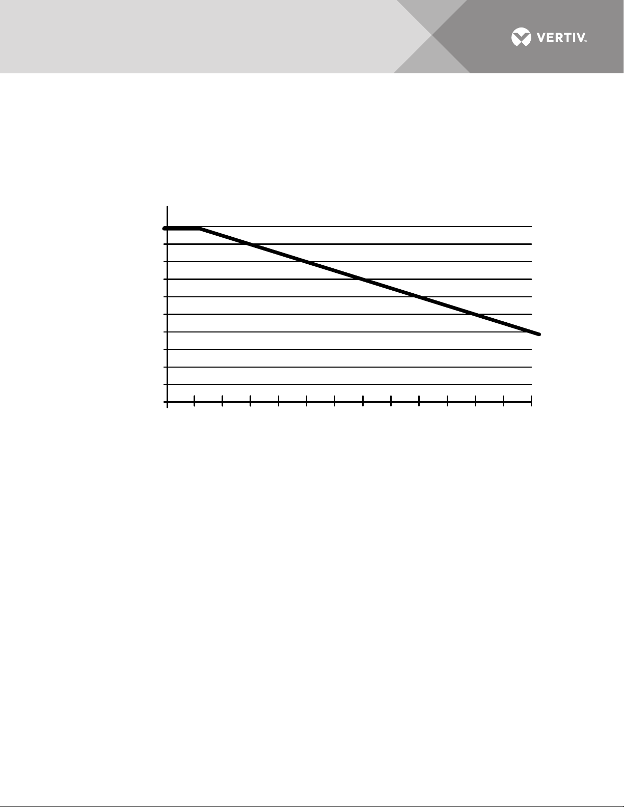
The standard units are designed for full load operation up to 4000 feet (1200m) above sea level. Above 4000
feet (1200m), output current is derated by 6% per 1000 feet.
Operation at full load at a higher altitude can be accommodated in ambient temperatures less than 104°F (40°C)
ambient. Figure 1 shows the maximum allowable ambient temperature for full load operation at altitudes above
4000 feet (1200 m).
Figure 1 Maximum ambient temperature for full load operation at higher altitudes
Vertiv™ | Liebert® STS2™ 100-1000A, 50/60Hz User Manual | Rev. 12 | 11/2017 7
Page 16

4.0 LOCATING THE LIEBERT STS2
This section provides instructions for leveling the Liebert STS2 and anchoring the unit to the floor, should that
be required.
For leveling feet details, see Figures 4 through 9.
4.1 Leveling and Anchoring the Unit to the Floor
The Liebert STS2 can be anchored to the concrete floor to ensure stability for the unit in the event of seismic
activity.
The seismic brackets are an option for the Liebert STS2 and are shipped separately from the unit when ordered.
See Figures 10 through 12 for instructions and details for installing seismic anchoring.
4.2 Leveling of the Static Switch Without Anchoring
The Liebert STS2 is furnished with casters and leveling feet. After final positioning of the unit, adjust the leveling
feet located in each corner of the frame base to level and stabilize the unit.
4.3 Leveling and Anchoring the Static Switch Using Floor Stand
The Liebert STS2 can be installed using the optional floor stand to support the unit instead of using the raised
floor. The Liebert STS2 can be rolled or placed using a lift on to the floor stand.
After final positioning of the unit, adjust the leveling feet located in each corner of the frame base to level and
stabilize the unit.
The floor stand can also be used to ensure the unit’s stability in the event of seismic activity by anchoring the
Liebert STS2 to the floor stand and to the concrete floor.
The seismic floor stand is shipped separately from the unit when ordered.
See Figures 29 through 40 for instructions and details for installing seismic floor stand.
Vertiv™ | Liebert® STS2™ 100-1000A, 50/60Hz User Manual | Rev. 12 | 11/2017 8
Page 17

5.0 POWER AND CONTROL WIRING
All power and control wiring should be installed by a qualified electrician. All power and control wiring must
comply with the NEC and applicable local codes. Unless otherwise labeled, use the recommended tightening
torque as shown in Table 20 - Torque tightening.
The busbars are accessible through the front of the Liebert STS2 and designed to allow one-handed tightening.
Cables can be installed through the top or bottom of the unit through removable conduits plates.
See Figures 4 through 9 for wiring entrance locations.
Input wiring also can be installed under a raised floor to optional input junction boxes and cables, when used.
5.1 Input And Output Power Connections
If the unit is furnished with input junction boxes, the input power connections are made to the input power
terminals located in the junction boxes. Input power cables, furnished with the input junction boxes, are shipped
unattached to the unit for connection between the junction boxes and the bus bars provided inside the unit.
Input junction box installation is discussed in 6.12 - Input Junction Box Installation—Optional on page 16.
If input junction boxes are not furnished, the input power connections are made to the bus bars provided inside
the unit. These bus bars are accessible through the front of the unit.
Output power connections also are made to the busbars provided inside the unit. These bus bars are accessible
through the front of the unit. See Figures 13 to 18 for details on the bus bars.
Aluminum or copper-clad aluminum wire can be used for equipment ratings 400A and above. Follow minimum
wire size ratings provided in submittal drawing PS214004.
5.1.1 Grounding
The Liebert STS2 operates from sources that are solidly grounded or impedance-grounded. The unit must not
be used on corner-grounded delta systems.
The AC output neutral is electrically isolated from the Liebert STS2 chassis. The Liebert STS2 chassis shall have
an equipment ground terminal.
WARNING
Risk of electric shock. Can cause equipment damage, injury and death.
Verify that all input power and control circuits are de-energized and locked out before making
connections inside unit.
The two input power feeds (sources) to the Liebert STS2 should be from two independent sources to avoid a
common source failure.
To ensure proper operation of the Liebert STS2, the two input sources must be the same nominal voltage level
and phase rotation.
For uninterrupted automatic transfer, the two input sources should be synchronized within 15 degrees.
CAUTION
Risk of unit damage.
The input sources to the static switch must be grounded-wye sources. Input sources other than solidly
grounded-wye sources may cause damage to the switch.
The Liebert STS2 is designed for operation with 3- or 4-wire, solidly grounded sources only.
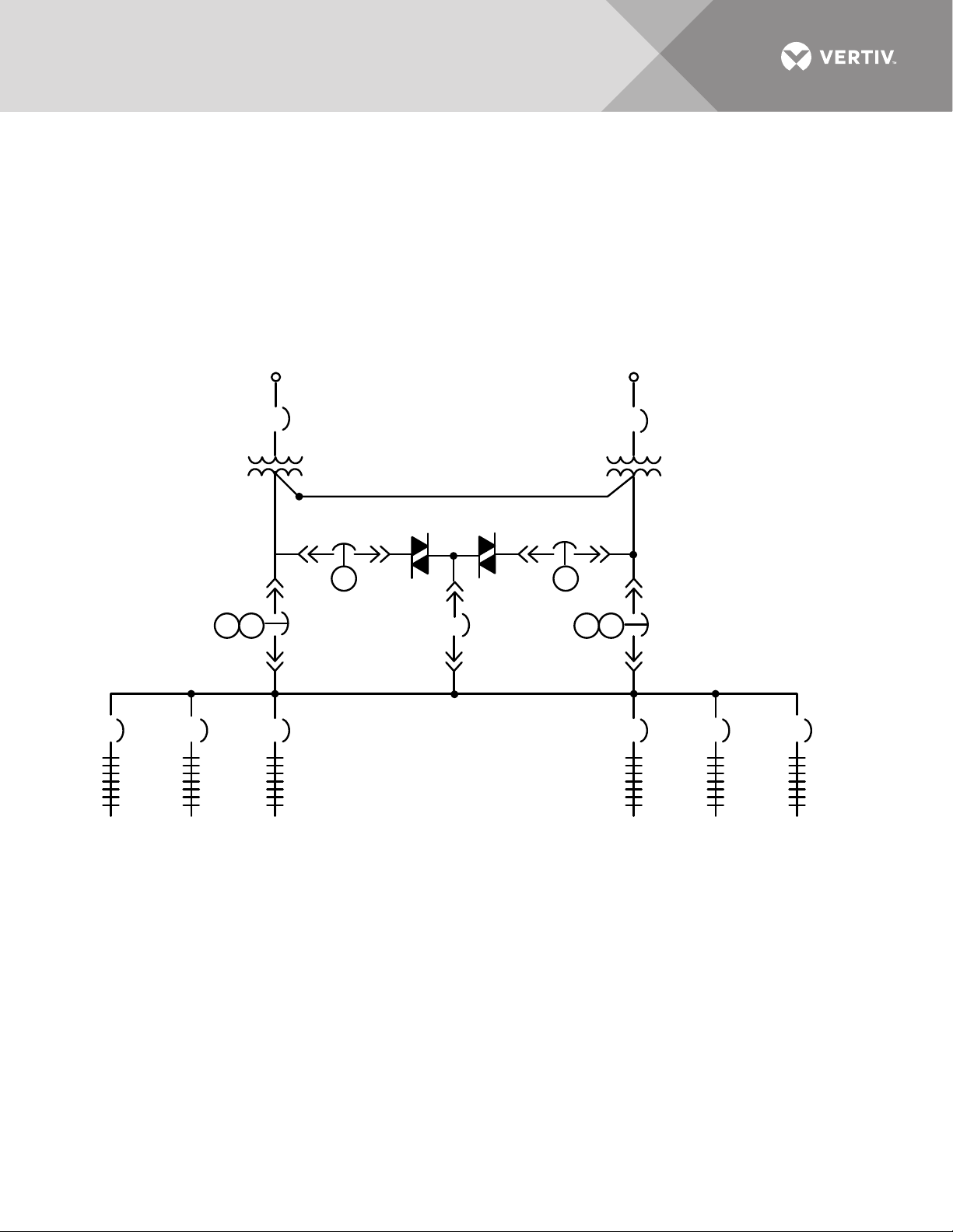
For 4-wire operation, the common source neutral must be connected to the Liebert STS2. See Figure 2 on
page 10 for a typical one-line diagram. Refer to Figures 13 to 18 for electrical field connections on all units, with
both single and dual output breakers.
Vertiv™ | Liebert® STS2™ 100-1000A, 50/60Hz User Manual | Rev. 12 | 11/2017 9
Page 18

Figure 2 Typical static transfer switch one-line diagram
K1 K3
K2 K3
K1 K2
OUTPUT
CB4 CB5CB3
SOURCE 1 SOURCE 2
STS1 STS2
CB1
CB2
The input and output power wire size should be based on the upstream overcurrent protection device, observing
the NEC and local codes.
The molded case switches contained in the Liebert STS2 are typically non-automatic circuit breakers that rely
on the upstream and/or load overcurrent protection. Upstream overcurrent protection should be rated equal to
or less than the rating of the Liebert STS2 molded case switches.
The Liebert STS2 input and output power and ground and neutral bus bars accommodate a wide range of wire
sizes. The Liebert STS2 busbars accommodate standard two-hole lugs.
Table 2 Input/output conduit plate specifications
Rating
100-250A 6 — 3" conduit
400-600A 9 — 4" conduit
800-1000A 12 — 4" conduits
Maximum Number
and Size
5.2 System Grounding
Equipment grounding — Grounding is primarily for equipment and personnel safety, although proper grounding
also enhances equipment performance.
All input and output power feeds must include an equipment grounding means as required by the NEC and local
codes.
An insulated equipment ground conductor is recommended to run with each input and output power feed. The
equipment ground conductors should be at least the minimum size conductor per the NEC based on the
upstream overcurrent protection device.
WARNING
If conduit is used as a grounding means, adequate electrical continuity must be maintained at all conduit
Vertiv™ | Liebert® STS2™ 100-1000A, 50/60Hz User Manual | Rev. 12 | 11/2017 10
connections. The use of isolating bushings with a metal conduit can be a safety hazard and is not
recommended.
Page 19
4-Wire-Plus-Ground Systems — When 4-wire-plus-ground input feeds are utilized, the input power sources
K1 K3K2 K3
K2K1
CB1
CB2
STS1 STS2
CB4 CB5CB3
225 A 225A 225 A 225A 225 A 225A
Source 1 Source 2
MICB1
MICB2
Isolation
Transformer
Isolation
Transformer
must be properly grounded. Because the neutral is not switched by the Liebert STS2, the neutrals of the two
power sources are solidly interconnected. The NEC prohibits grounding a power source at more than one point.
Connecting the neutrals of two grounded power sources together effectively grounds each of the sources at
more than one point, which allows neutral current to flow on the ground system, defeats ground fault protection,
creates a safety hazard, and violates the NEC.
Where possible, the two power sources should be located in close proximity and a single neutral-to-ground bond
made (as shown in Figure 3 or as is typical with a double-ended substation).
Figure 3 Typical one-line diagram of two PDUs and a Liebert STS2
Vertiv™ | Liebert® STS2™ 100-1000A, 50/60Hz User Manual | Rev. 12 | 11/2017 11
Page 20
5.3 Control Wiring Connections
No control wiring is needed on the standard Liebert STS2. Only certain options require external control wiring.
See 6.0 - Options on page 13 for details
5.4 Power Supply
The Liebert STS2 is supplied with redundant power supplies that are designed to operate from a voltage range
of 200V to 600V. The unit is set at the factory to match the nameplate voltage. Field adjustments are not
necessary. If the unit needs to operate at a voltage other than what is listed on the nameplate, contact Vertiv
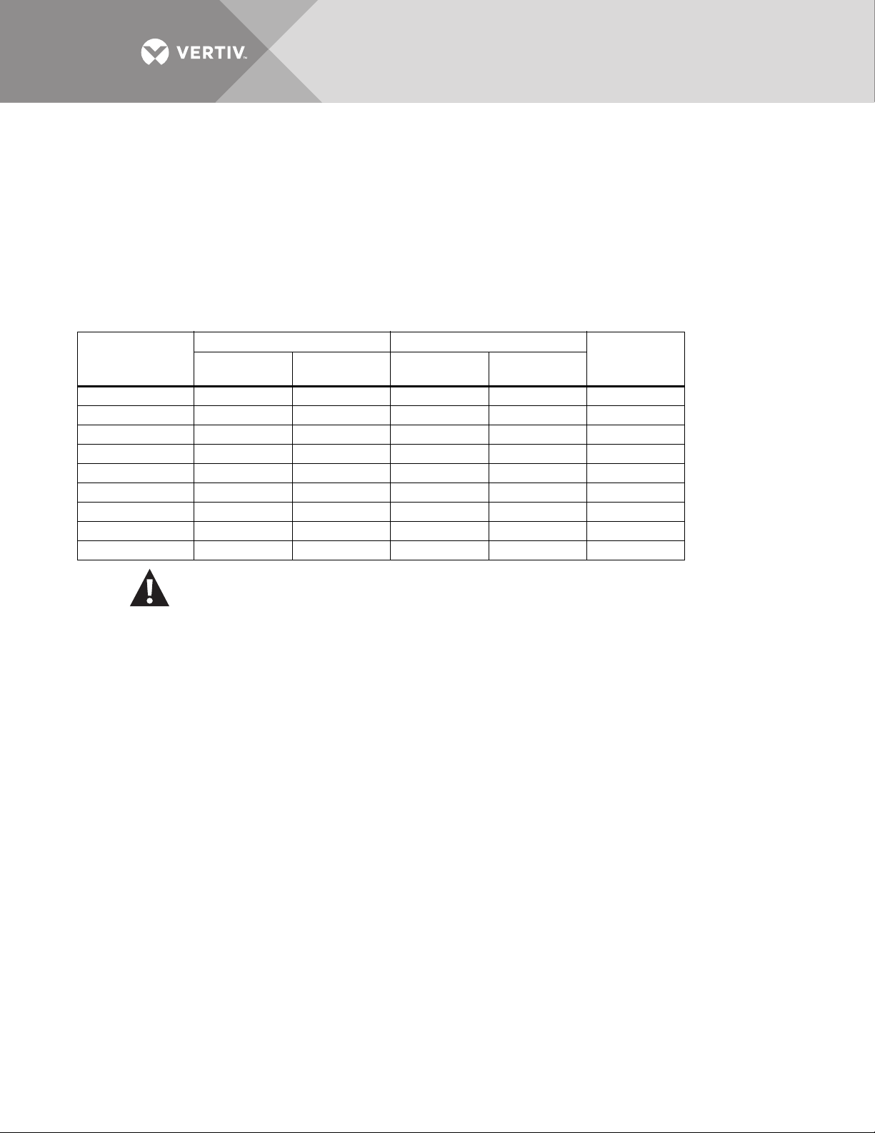
Services or your local Vertiv representative. Tab le 3 provides transformer tap information.
Table 3 Terminal Block 1 and Terminal Block 2 wire connections
Connect Connect
Vol tage
200 1 9 1 9 1-7
208 1 10 1 10 1-7
220 2122126-8
240 1111111-7
380 1 8 1 8 2-7
400 1 9 1 9 3-7
415 1 10 1 10 4-7
480 1 11 1 11 5-7
600 1 12 1 12 6-7
F1
TB1-XX
F2
TB1-YY
F3
TB2-XX
F4
TB2-YY
Jumper
Between
CAUTION
Using Table 3, ensure that the wiring for the control transformers matches the input voltage for the unit.
Improper wiring could result in blown fuses.
Vertiv™ | Liebert® STS2™ 100-1000A, 50/60Hz User Manual | Rev. 12 | 11/2017 12
Page 21

6.0 OPTIONS
This section discusses the options available for the Liebert STS2. The communications options are also
discussed in 12.0 - Communication Interfaces.
6.1 Programmable Relay Board
The Programmable Relay Board (PRB) provides a means to trigger an external device when an event occurs in
the Liebert STS2. Each PRB has eight channels. Each channel has one set of Form-C dry contacts.
Any alarm/event can be programmed to any channel or channels. Up to ten (10) events can be programmed to a
relay. If multiple events are grouped to one relay, group the events logically to simplify troubleshooting when an
event is triggered. The same alarm/event can be programmed to more than one channel. Up to two
Programmable Relay Boards can be installed in the Liebert STS2 for a total of 16 channels. Programming is
performed through the touchscreen display.
See Configuring the Programmable Relay Board Settings on page 92 for default settings and instructions for
reconfiguring the relays. See Figures 19 and 20 for the location of the PRB. See Figure 22 for wiring details.
6.2 Optimized Transfer
When the Liebert STS2 is used as a primary-side switch—on the primary of an isolation transformer—optimized
transfer greatly reduces the transformer magnetization current during automatic transfers through a new,
patented transfer control algorithm. The Liebert algorithm optimizes the transfer timing so that the volt-seconds
applied to the downstream transformer primary is balanced, minimizing peak saturation current.
The volt-second balance is achieved by directly computing the volt-second applied to the transformer during
transfer events and determining the optimum time to turn on the alternate source SCRs in order to balance the
volt-second within specified tolerance.
Optimized transfer also seeks to minimize the voltage disturbances while still maintaining transformer flux
balance. This unique flux balance algorithm does not just wait for the balance point to occur, but will pulse fire
the SCRs as soon as possible to minimize the voltage disruption. This results in far superior voltage waveforms
applied to the load.
6.3 Distribution Cabinet With I-Line Panelboard—100-600A Units Only
A distribution cabinet with a Square D I-Line panelboard offers space to plug in up to 10 three-pole branch
circuit breakers (100A-250A). The panelboard is rated at 600A with an overall short-circuit rating of
100,000 AIC.
The full-height cabinet mounts on either the right or left side of the Liebert STS2 and is fully enclosed with a
keylock door and an accent cover that permits access to the panelboard without exposing other portions of the
Liebert STS2.
6.4 Input Contact Isolator Board
The Input Contact Isolator Board (ICI) provides an Liebert STS2 module interface for up to eight external user
alarm or message inputs to be routed through the Liebert STS2’s alarm network. The eight contacts are normally
open dry contacts. When a contact closes, an event is triggered.
The Input Contact Isolator options are configured through the Input Contact Isolator dialog box, which is
accessed from the Comm Option dialog box on the touchscreen display. You also can program the alarm
messages through this dialog box. See Configuring the Input Contact Isolator Settings on page 91 for
instructions on configuring the connections.
See Figures 19 and 20 for the location of the ICI. See Figure 23 for wiring details.
Vertiv™ | Liebert® STS2™ 100-1000A, 50/60Hz User Manual | Rev. 12 | 11/2017 13
Page 22

6.5 Comms Board
The Comms Board provides a communication interface to Liebert SiteScan, a site monitoring product. Liebert
SiteLink™-12 or Liebert SiteLink-4 is required for Liebert SiteScan to communicate with the Liebert STS2.
The Comms Board is equipped with an RS-422 communication port for communication to a Liebert SiteScan
monitoring system using a two-wire twisted pair for reliable communication up to 1000 meters (3281 ft.).
Information available from the RS-422 port includes the present switch status information, all monitoring
parameters, and all active alarms.
Programming the Comms Board is performed through the touchscreen display. See Comm Options on page 90
for details.
See Figures 19 and 20 for the location of the Comms Board.
See Figure 24 for information on the control wiring.
6.6 Liebert IntelliSlot™ SNMP/Web/Modbus 485 Card
A Liebert IntelliSlot SNMP/Web/Modbus 485 card enables the Liebert STS2 to communicate to a network
management system (NMS). The card provides the internal hardware and software to communicate, via
SNMP/Web (HTTP), to any IP-based Ethernet network through an RJ-45 connector using Category 5 cabling.
The Liebert SNMP/Web/Modbus 485 card provides redundant paths for communications that make it possible
to connect to a Building Management System (BMS) using Modbus, while simultaneously communicating to a
NMS through SNMP/Web (HTTP). A terminal block provides the connection to Modbus.
See Figures 19 and 20 for the location of the Liebert SNMP/Web/Modbus 485 card. See Figure 25 control wiring
information.
If you have questions about the Liebert SNMP/Web/Modbus 485 card, refer to the user guide, SL-52615, available
at the Liebert Web site, www.vertivco.com
6.7 LED Display
A light-emitting diode display is available to replace the standard liquid crystal display touchscreen control. The
display provides monitoring and control through a series of LED’s and buttons. LED’s alert you when a problem
occurs. A PC running terminal emulation software connected to the RS-232 port is needed to access the data
and configuration settings.
Vertiv™ | Liebert® STS2™ 100-1000A, 50/60Hz User Manual | Rev. 12 | 11/2017 14
Page 23

6.8 Remote Source Selection Wiring
An optional Remote Source Selection board may be installed in your Liebert STS2. This board is installed in the
same bay as the communications options. See Figures 19 and 20 for the location of these options. See
Figure 21 for information on the control wiring for the Remote Source Selection option.
The Remote Source Selection allows you to choose the preferred input source from a remote location. Terminal
connections allow the customer to remotely select a source to be the preferred source in the same process as
the local source transfer selection.
The unit’s preferred source selection and Remote Source Selection are active at the same time, with the Liebert
STS2 following the last request for a preferred source change, regardless of whether it was from the local or
Remote Source Selection controls.
A six pin terminal block provides the Remote Source Selection connections. Two pairs of wires are used from the
switch to trigger the source selection. You can select the type of switch used for this remote control. Connections
are made to four of the connections, using Form A dry contacts. The contacts are numbered left to right:
Table 4 Remote source selection terminal block
Contact
1Source 1
2 Isolated ground
3Source 2
4 Isolated Ground
5 DO NOT USE
6 DO NOT USE
Connection
See 10.3 - Enabling Remote Source Selection for instructions on enabling the Remote Source Selection option.
6.9 Key Lockout Switch
The key lockout switch activates a software lockout of the touchscreen display to prevent manual transfers and
configuration changes. When locked out, the touchscreen becomes a read only display. A key is needed to do
manual transfers or change settings.
The alarm silence button is not disabled when in the lockout position.
The switch is located behind the front door but can be operated without opening the front door. See Figures 7
to 9 for the key lockout location on each unit.
See section 13.2.1 - Security for key lockout switch operation with the LCD touchscreen. See 14.1.4 - Key
Lockout Switch for key lockout switch operation with the LED display.
6.10 Redundant Output Breaker
An output plug-in, non-automatic circuit breaker is provided which allows redundancy in the output power path.
The breaker is connected in parallel with the output plug-in non-automatic circuit breaker.
6.11 Transfer Inhibit
Transfer Inhibit prevents the Liebert STS2 from transferring under certain conditions. When a customer-supplied
closed dry contact is provided, the Liebert STS2 will not transfer and remain on its present source even if the
source is no longer supplying power.
This option requires an Input Contact Isolator board (see 6.4 - Input Contact Isolator Board).
Vertiv™ | Liebert® STS2™ 100-1000A, 50/60Hz User Manual | Rev. 12 | 11/2017 15
Page 24

6.12 Input Junction Box Installation—Optional
The input junction box option is available to simplify input connections to the Liebert STS2. Two input junction
boxes and the associated flexible 10 foot long (3 meter) input cables are provided with this option.
This option is available only with bottom cable entrance, typically when the unit is located on a raised floor.
If the input junction boxes will be used, they may be shipped either with the unit or in advance to be installed
during the rough-in stage of construction.
Locate the junction boxes a maximum of 8 feet (2.4 meters) from the planned location of the Liebert STS2.
Due to a lack of clearance for the cables below the unit, the cables are also shipped loose from the unit for
installation at the site. The input cables connect from the input junction boxes to the input power bus bars inside
the Liebert STS2.
The standard configuration for the input junction boxes and cables is for 3-wire-plus-ground feeds. If the input
neutral is required, special 4-wire-plus-ground input cables and junction boxes are required. See Figure 27 for
wiring details.
6.13 Seismic Floor Anchors
Seismic anchors are available for anchoring the unit to a concrete floor to meet seismic Zone 4 requirements.
See 4.1 - Leveling and Anchoring the Unit to the Floor on page 8 for more information. Installation details are
provided in Figures 10 through Figure 12.
6.14 Seismic Floor Stand
Seismic floor stands in four heights—18", 24", 30" and 36" (457mm, 610mm, 762mm and 914mm)—are available
for the Liebert STS2. The stands can be fastened to the floor to meet seismic Zone 4 requirements. See 4.0 -
Locating the Liebert STS2 and Figures 29 through 40 for instructions and details for installing seismic floor
stands.
Vertiv™ | Liebert® STS2™ 100-1000A, 50/60Hz User Manual | Rev. 12 | 11/2017 16
Page 25
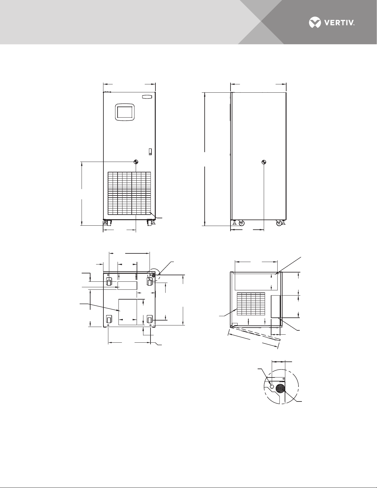
7.0 INSTALLATION DRAWINGS
PS211100
Rev. 6
30" (762mm)
36.7"
(932mm)
23.4" (594mm)
Caster Centers
12mm
Centers
29"
(736mm)
12mm Diameter
Mounting Hole
(4 Typically)
See Note 10
12mm
Centers
21.6"
(548mm)
Caster
Centers
12.8"
(326mm)
2.75"
(69.8mm)
Typical
13.5"
(343mm)
29.8"
(756mm)
NOTES
1. 18" (457mm) clearance above unit is required for air exhaust.
2. Clearance of 36" (914mm) is required in the front only for
installation and service access.
3. Heat output: 2710 BTU/Hr (0.80kW) maximum for 100A switch.
4680 BTU/Hr (1.37kW) maximum for 250A switch.
4. Weight: 780 lb. (354kg)
5. Unit bottom is structurally adequate for forklift handling.
6. Keep cabinet within 15 degrees of vertical.
7. Color: Black gray matte
9. Open door to replace air filter, disposable type 1"x25"x25"
(25.4 x 635 x 635mm).
10. Threaded mounting holes (see Detail A) are provided for seismic
anchoring or floor stand. Mounting bolts must be threaded into
the unit from underneath the unit base. If a floor stand is used,
the casters must rest on the floor stand to support the unit's weight.
32.1" (815mm)
77"
(1956mm)
18.8"
(477mm)
11. 1"
(280mm)
1.1"
(28mm)
5.1"
(130mm)
10.4"
(265mm)
14.8"
(376mm)
10.7"
(272mm)
24.4"
(619mm)
9.4" (238mm)
8.4" (213mm)
21.5"
(546mm)
19.2"
(488mm)
24.4"
(620mm)
Center
of
Gravity
Center
of
Gravity
Air Intake Area
Do Not Block
Air Filter
FRONT
FRONT
FRONT
SIDE
TOP
DETAIL A
Front of Unit Shown
Without Side Panel
See
Detail A
Power Cable
Bottom Entry Area
Control Cable
Bottom Entry Area
Power Cable
Top Entry Area
Control Cable
Top Entry Area
Maximum Door
Swing 180º
Air
Exhaust
Leveler
Figure 4 Outline drawing: 100 – 250 amp Liebert STS2
Vertiv™ | Liebert® STS2™ 100-1000A, 50/60Hz User Manual | Rev. 12 | 11/2017 17
Page 26

Figure 5 Outline drawing: 400 – 600 amp Liebert STS2
PS211400
Rev. 4
38" (965mm)
36.3"
(923mm)
31.3" (794mm)
Caster Centers
12mm
Centers
29"
(736mm)
12mm Diameter
Mounting Hole
(4 Typically)
See Note 10
12mm
Centers
21.6"
(548mm)
Caster
Centers
12.8"
(326mm)
2.75"
(69.8mm)
Typical
15.7"
(399mm)
29.6"
(752mm)
NOTES
1. 18" (457mm) clearance above unit is required for air exhaust.
2. Clearance of 36" (914mm) is required in the front only for
installation and service access.
3. Heat output: 6970 BTU/Hr (2.04kW) maximum for 400A switch.
10,520 BTU/Hr (3.08kW) maximum for 600A switch.
4. Weight: 1200 lb. (544kg)
5. Unit bottom is structurally adequate for forklift handling.
6. Keep cabinet within 15 degrees of vertical.
7. Color: Black gray matte
9. Open door to replace air filter, disposable type 1"x25"x25"
(25.4 x 635 x 635mm).
10. Threaded mounting holes (see Detail A) are provided for seismic
anchoring or floor stand. Mounting bolts must be threaded into
the unit from underneath the unit base. If a floor stand is used,
the casters must rest on the floor stand to support the unit's weight.
32.1" (815mm)
77"
(1956mm)
18.6"
(474mm)
11. 5"
(292mm)
10.5"
(267mm)
4.6"
(116mm)
.97"
(25mm) Ref.
5.1"
(130mm)
32.5" (825mm)
3.5" (88mm)
13.5"
(343mm)
13.3"
(337mm)
17.1"
(435mm)
7.8"
(198mm)
21.4"
(544mm)
14.6"
(372mm)
35.8" (910mm)
9" (228mm)
Center
of
Gravity
Center
of
Gravity
Air Intake Area
Do Not Block
Air Filter
FRONT
FRONT
FRONT
SIDE
TOP
BOTTOM
DETAIL A
Front of Unit Shown
Without Side Panel
See
Detail A
Power Cable
Bottom Entry
Area
Control Cable
Bottom Entry Area
Power Cable Top Entry Area
Control Cable
Top Entry Area
Maximum Door
Swing 180º
Air
Exhaust
Leveler
Vertiv™ | Liebert® STS2™ 100-1000A, 50/60Hz User Manual | Rev. 12 | 11/2017 18
Page 27
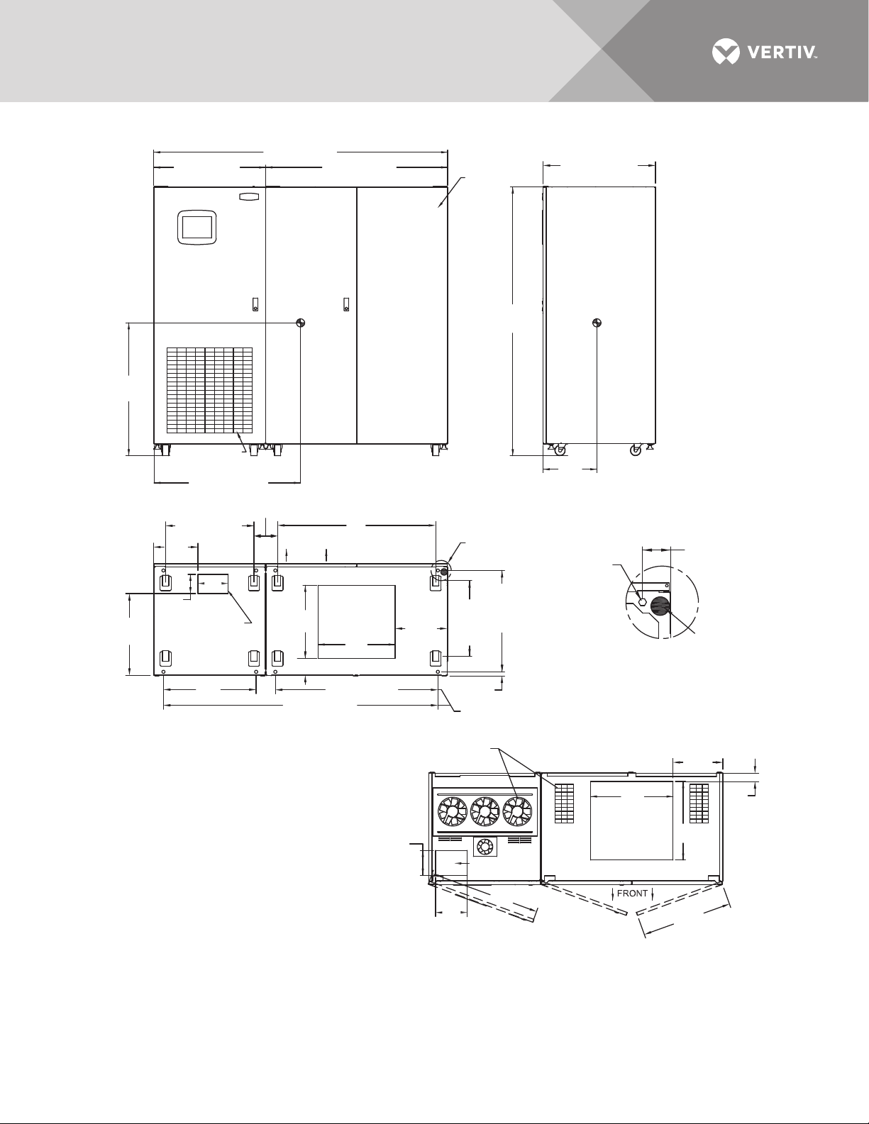
Figure 6 Outline drawing: 800 – 1000 amp Liebert STS2
84" (2134mm)
32" (813mm)
52" (1321mm)
Breaker
Cabinet
32.1" (815mm)
Center
of
Gravity
38"
(965mm)
23.3"
(592mm)
Air Intake Area
Do Not Block
Air Filter
41.9" (1064mm)
25.3" (642mm)
12.7"
(323mm)
(220mm)
5.5"
(140mm)
Control Cable
Bottom Entry Area
26.5"
(673mm)
8.7"
6.7"
(171mm)
5.5"
(139mm)
FRONT
20.9"
(530mm)
4.8" (122mm)
78.4" (1992mm)
FRONT
45.2" (1149mm)
Caster Centers
Power Cable
Bottom Entry
Area
22.1"
(560mm)
46.4" (1180mm)
BOTTOM
NOTES
1. 18" (457mm) clearance above unit is required
for air exhaust.
2. Clearance of 36" (914mm) is required in the
front only for installation and service access.
3. Heat output: 13,780 BTU/Hr (4.03kW) maximum
for 800A switch.
17,390 BTU/Hr (5.09kW) maximum
for 1000A switch.
4. Weight: 2500 lb. (1134kg)
5. Unit bottom is structurally adequate for forklift
handling.
6. Keep cabinet within 15 degrees of vertical.
7. Color: Black gray matte
8. Open door to replace air filter, disposable type
1"x25"x25" (25.4 x 635 x 635mm).
9. Threaded mounting holes (see Detail A) are provided
for seismic anchoring or floor stand. Mounting bolts
must be threaded into the unit from underneath
the unit base. If a floor stand is used,
the casters must rest on the floor stand to support
the unit's weight.
10. 500 CFM (236 L/S) per exhaust fan.
(378mm)
7.1"
(180mm)
14.9"
See
Detail A
21.6"
(548mm)
Caster
Centers
(25mm), Ref.
12mm
Centers
Air Exhaust,
Typical
Control Cable
Top Entry Area
9.1"
(230mm)
77"
(1956mm)
12mm
Centers
29"
(736mm)
.98"
31.9"
(810mm)
PS211800
Rev. 4
Center
of
Gravity
15.4"
(391mm)
12mm Diameter
Mounting Hole
(4 Typically)
See Note 9
Top Entry Area
TOP
SIDE
DETAIL A
Front of Unit Shown
Without Side Panel
(361mm)
23.6"
(600mm)
Power Cable
FRONT
22.4"
(570mm)
25.8"
(655mm) Typical
Maximum Door
Swing 180º
2.75"
(69.8mm)
Typical
Leveler
14.2"
2.4"
(61mm)
Vertiv™ | Liebert® STS2™ 100-1000A, 50/60Hz User Manual | Rev. 12 | 11/2017 19
Page 28
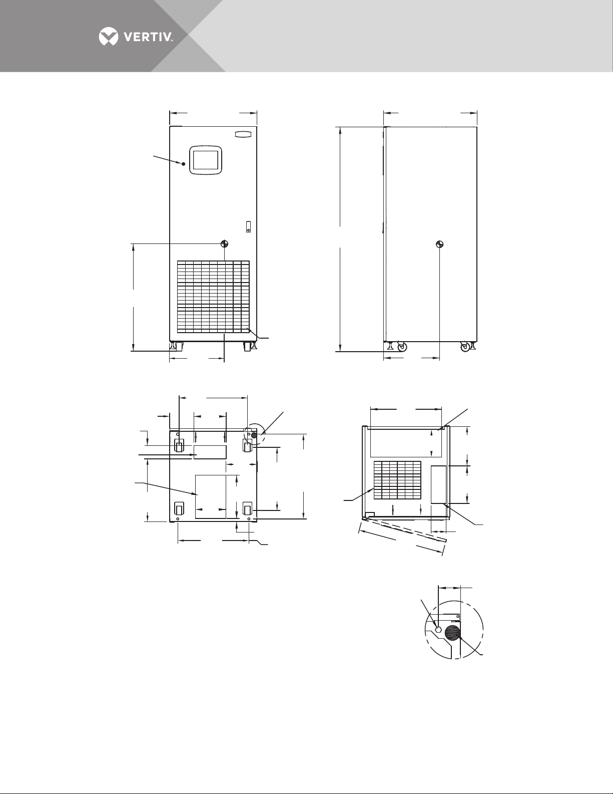
Figure 7 Outline drawing: 100 – 250amp Liebert STS2 with a key lockout switch option
30" (762mm)
Key
Lockout
Switch
Center
of
Gravity
77"
(1956mm)
36.7"
(932mm)
Air Intake Area
18.8"
(477mm)
Do Not Block
Air Filter
FRONT
23.4" (594mm)
Caster Centers
8.4" (23.4mm)
4.6" (116mm)
Control Cable
Bottom Entry Area
Power Cable
Bottom Entry Area
21.5"
(546mm)
NOTES
11. 1"
(280mm)
FRONT
10.7"
(272mm)
14.8"
(376mm)
10.4"
(265mm)
24.4"
(619mm)
BOTTOM
1. 18" (457mm) clearance above unit is required for air exhaust.
2. Clearance of 36" (914mm) is required in the front only for
installation and service access.
3. Heat output: 2710 BTU/Hr (0.80kW) maximum for 100A switch.
4680 BTU/Hr (1.37kW) maximum for 250A switch.
4. Weight: 780 lb. (354kg)
5. Unit bottom is structurally adequate for forklift handling.
6. Keep cabinet within 15 degrees of vertical.
7. Color: Black gray matte
9. Open door to replace air filter, disposable type 1"x25"x25"
(25.4 x 635 x 635mm).
10. Threaded mounting holes (see Detail A) are provided for seismic
anchoring or floor stand. Mounting bolts must be threaded into
the unit from underneath the unit base. If a floor stand is used,
the casters must rest on the floor stand to support the unit's weight.
21.6"
(548mm)
Caster
Centers
1.1"
(28mm)
12mm
Centers
See
Detail A
12mm
Centers
29"
(736mm)
Air
Exhaust
Maximum Door
Swing 180º
32.1" (815mm)
19.2"
(488mm)
SIDE
24.4"
(620mm)
9.4" (238mm)
FRONT
29.8"
(756mm)
TOP
12mm Diameter
Mounting Hole
(4 Typically)
See Note 10
Center
of
Gravity
Power Cable
Top Entry Area
13.5"
(343mm)
12.8"
(326mm)
Control Cable
5.1"
(130mm)
Top Entry Area
2.75"
(69.8mm)
Typical
Leveler
DETAIL A
Front of Unit Shown
Without Side Panel
PS211101
Rev. 5
Vertiv™ | Liebert® STS2™ 100-1000A, 50/60Hz User Manual | Rev. 12 | 11/2017 20
Page 29
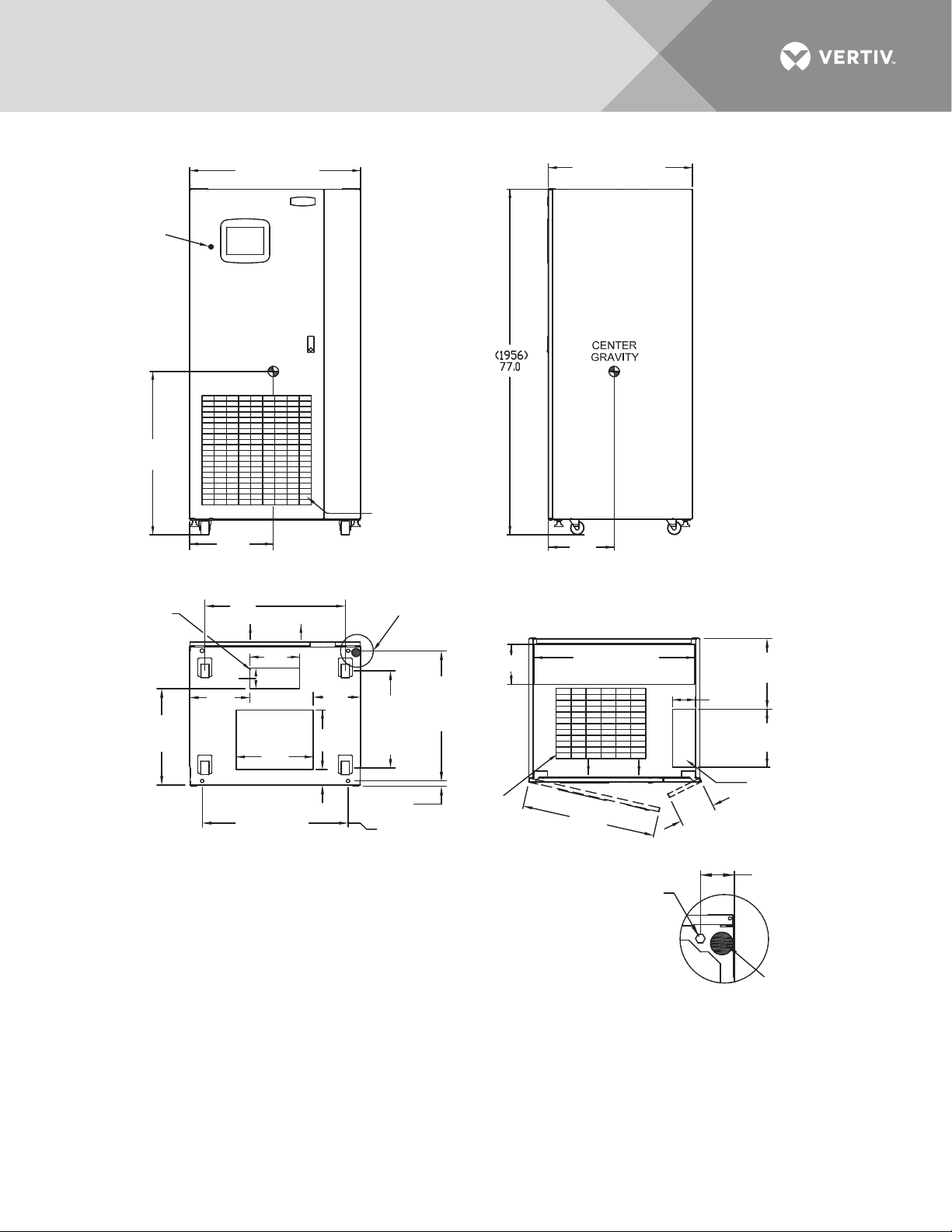
Figure 8 Outline drawing: 400 – 600 amp Liebert STS2 with a key lockout switch option
32.1" (815mm)
Center
of
Gravity
14.6"
(372mm)
SIDE
35.8" (910mm)
Power Cable Top Entry Area
FRONT
29.6"
(752mm)
TOP
Key
Lockout
Switch
36.3"
(923mm)
Control
Cable
Bottom
Entry Area
21.4"
(544mm)
18.6"
(474mm)
31.3" (794mm)
Caster Centers
4.6"
(116mm)
13.5"
(343mm)
38" (965mm)
Center
of
Gravity
FRONT
FRONT
11. 5"
(292mm)
Power Cable
Bottom Entry
Area
17.1"
(435mm)
3.5" (88mm)
32.5" (825mm)
BOTTOM
10.5"
(267mm)
13.3"
(337mm)
Air Intake Area
Do Not Block
Air Filter
See
Detail A
21.6"
(548mm)
Centers
(736mm)
Caster
.97"
(25mm) Ref.
12mm
Centers
77"
(1956mm)
9" (228mm)
12mm
Centers
29"
Air
Exhaust
NOTES
1. 18" (457mm) clearance above unit is required for air exhaust.
2. Clearance of 36" (914mm) is required in the front only for
installation and service access.
3. Heat output: 6970 BTU/Hr (2.04kW) maximum for 400A switch.
10,520 BTU/Hr (3.087kW) maximum for 600A switch.
4. Weight: 1200 lb. (544kg)
5. Unit bottom is structurally adequate for forklift handling.
6. Keep cabinet within 15 degrees of vertical.
7. Color: Black gray matte
9. Open door to replace air filter, disposable type 1"x25"x25"
(25.4 x 635 x 635mm).
10. Threaded mounting holes (see Detail A) are provided for seismic
anchoring or floor stand. Mounting bolts must be threaded into
the unit mounting holes from underneath the unit base. If a floor
stand is used, the casters must rest on the floor stand to support
the unit's weight.
12mm Diameter
Mounting Hole
(4 Typically)
See Note 9
PS211401
Rev. 4
15.7"
(399mm)
5.1"
(130mm)
12.8"
(326mm)
Control Cable
Top Entry Area
7.8"
(198mm)
Maximum Door
Swing 180º
2.75"
(69.8mm)
Typical
Leveler
DETAIL A
Front of Unit Shown
Without Side Panel
Vertiv™ | Liebert® STS2™ 100-1000A, 50/60Hz User Manual | Rev. 12 | 11/2017 21
Page 30
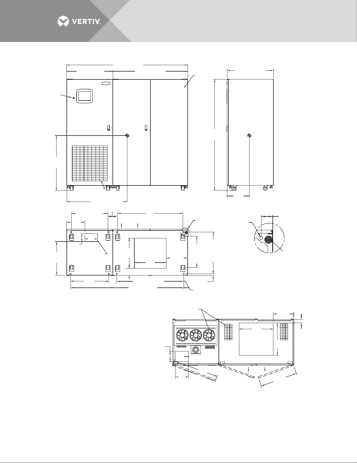
Figure 9 Outline drawing: 800 – 1000 amp Liebert STS2 with the key lockout switch option
84" (2134mm)
52" (1321mm)
Breaker
Cabinet
Key
Lockout
Switch
45.2" (1149mm)
Caster Centers
12mm
Centers
29"
(736mm)
12mm Diameter
Mounting Hole
(4 Typically)
See Note 9
12mm
Centers
21.6"
(548mm)
Caster
Centers
2.75"
(69.8mm)
Typical
NOTES
1. 18" (457mm) clearance above unit is required
for air exhaust.
2. Clearance of 36" (914mm) is required in the
front only for installation and service access.
3. Heat output: 13,780 BTU/Hr (4.03kW) maximum
for 800A switch.
17,390 BTU/Hr (5.09kW) maximum
for 1000A switch.
4. Weight: 2500 lb. (1134kg)
5. Unit bottom is structurally adequate for
forklift handling.
6. Keep cabinet within 15 degrees of vertical.
7. Color: Black gray matte
8. Open door to replace air filter, disposable
type 1"x25"x25"
(25.4 x 635 x 635mm).
9. Threaded mounting holes (see Detail A) are
provided for seismic anchoring or floor stand.
Mounting bolts must be threaded into
the unit from underneath the unit base.
If a floor stand is used, the casters must
rest on the floor stand to support the unit's weight.
10. 500 CFM (236 L/S) per exhaust fan.
32" (813mm)
32.1" (815mm)
77"
(1956mm)
.98"
(25mm), Ref.
4.8" (122mm)
41.9" (1064mm)
6.7"
(171mm)
20.9"
(530mm)
78.4" (1992mm)
46.4" (1180mm)
26.5"
(673mm)
22.1"
(560mm)
14.9"
(378mm)
7.1"
(180mm)
9.1"
(230mm)
2.4"
(61mm)
22.4"
(570mm)
14.2"
(361mm)
23.6"
(600mm)
25.8"
(655mm) Typical
31.9"
(810mm)
5.5"
(139mm)
15.4"
(391mm)
Center
of
Gravity
Center
of
Gravity
Air Intake Area
Do Not Block
Air Filter
FRONT
FRONT
FRONT
SIDE
TOP
PS211801
Rev. 4
BOTTOM
DETAIL A
Front of Unit Shown
Without Side Panel
See
Detail A
Power Cable
Bottom Entry
Area
Control Cable
Bottom Entry Area
Power Cable
Top Entry Area
Maximum Door
Swing 180º
Air Exhaust,
Typical
Leveler
38"
(965mm)
23.3"
(592mm)
12.7"
(323mm)
5.5"
(140mm)
25.3" (642mm)
8.7"
(220mm)
Control Cable
Top Entry Area
Vertiv™ | Liebert® STS2™ 100-1000A, 50/60Hz User Manual | Rev. 12 | 11/2017 22
Page 31
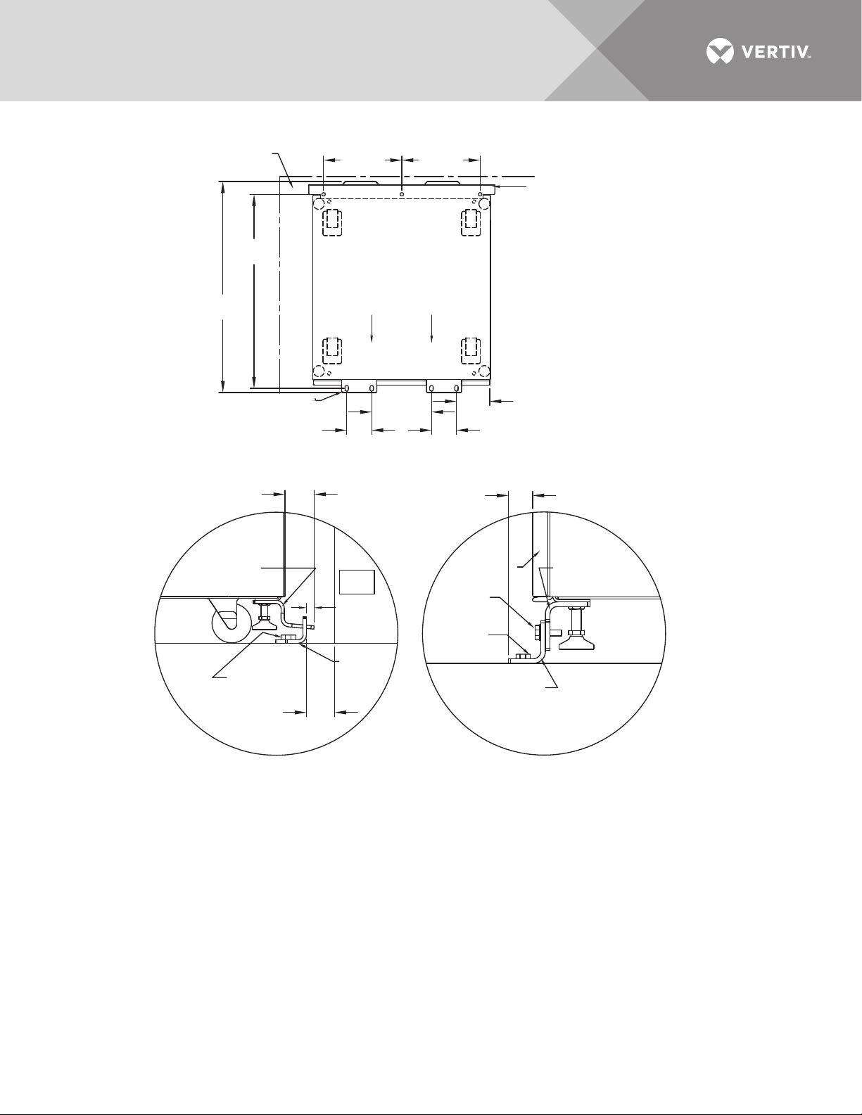
Figure 10 Seismic anchor drawing: 100 – 250 amp Liebert STS2
See Note 7
for spacing
32.75"
(832mm)
35.72"
(907mm)
Side Wall
Front Floor
Bracket
4.2"
(107mm)
13.2"
(335mm)
13.2"
(335mm)
Front
10.1"
(256mm)
TOP
System Seismic Anchoring, Figure 1
2.26"
(57.5mm)
Back Wall
Rear Floor
Bracket
See Note 2
for spacing
5.75"
(146mm)
4.2"
(107mm)
1.364"
(34.6mm)
Rear Cabinet
Base Bracket
Floor Line
Floor Anchor
Hardware
(Field-Supplied)
(19mm)
Back
Wall
1/2"
(12.5mm)
Approx.
Rear Floor
Bracket
3/4"
Figure 2
NOTES
1. Recommended floor anchor: 1/2" ITW Ramset/Red Head
self-drilling anchor; ICBO #ER-1372 or equivalent (not
supplied. Follow manufacturer's instructions.
2. Position rear floor brackets on floor at least 0.75" (19mm)
from back wall. Mark location and drill holes (Figure 1) to
a minimum depty of 4.12" (104.7mm) into the concrete.
3. Install rear cabinet base bracket (Figure 2) to existing holes
on the underside of the unit with tabs facing the back wall.
Use supplied hardware and torque to 365 lb./in. (41.2Nm).
Loosen leveling bolt locking nut and tighten after the
bracket is secured.
4. Install the front cabinet base (Figure 3) to existing holes
on the underside of the unit with the bent flange facing front.
Use the supplied hardware and torque to
365 lb./in. (41.2Nm). Loosen leveling bolt locking nut and
tighten after the bracket is secured.
Front Door
of Cabinet
Hardware
Supplied
Floor Anchor
Hardware
(Field-Supplied)
Front Floor
Bracket
Front Cabinet
Base Bracket
Floor Line
Figure 3
5. Move the cabinet into position with the rear tabs into the
slots of the floor bracket. The tabs must extend at least
1/2" (12.7mm) through the floor bracket (Figure 2).
Then attach the front floor brackets to the front cabinet
base bracket, but do not fully tighten the hardware.
6. Mark the hole locations and remove the brackets. Drill
and install the floor brackets. The unit door can be removed
for better access. Reinstall the front floor brackets to the
front cabinet brackets with the supplied hardware and
torque to 235 lb./in. 26.5Nm), see Figure 3.
7. If side walls are present, minimum distance from either
side wall is required.
8. Rear and front floor brackets and the rear and front cabinet
base brackets are 1010 steel and approximately 1/4"
(6.4mm) thick.
PS211105
Rev. 1
Vertiv™ | Liebert® STS2™ 100-1000A, 50/60Hz User Manual | Rev. 12 | 11/2017 23
Page 32
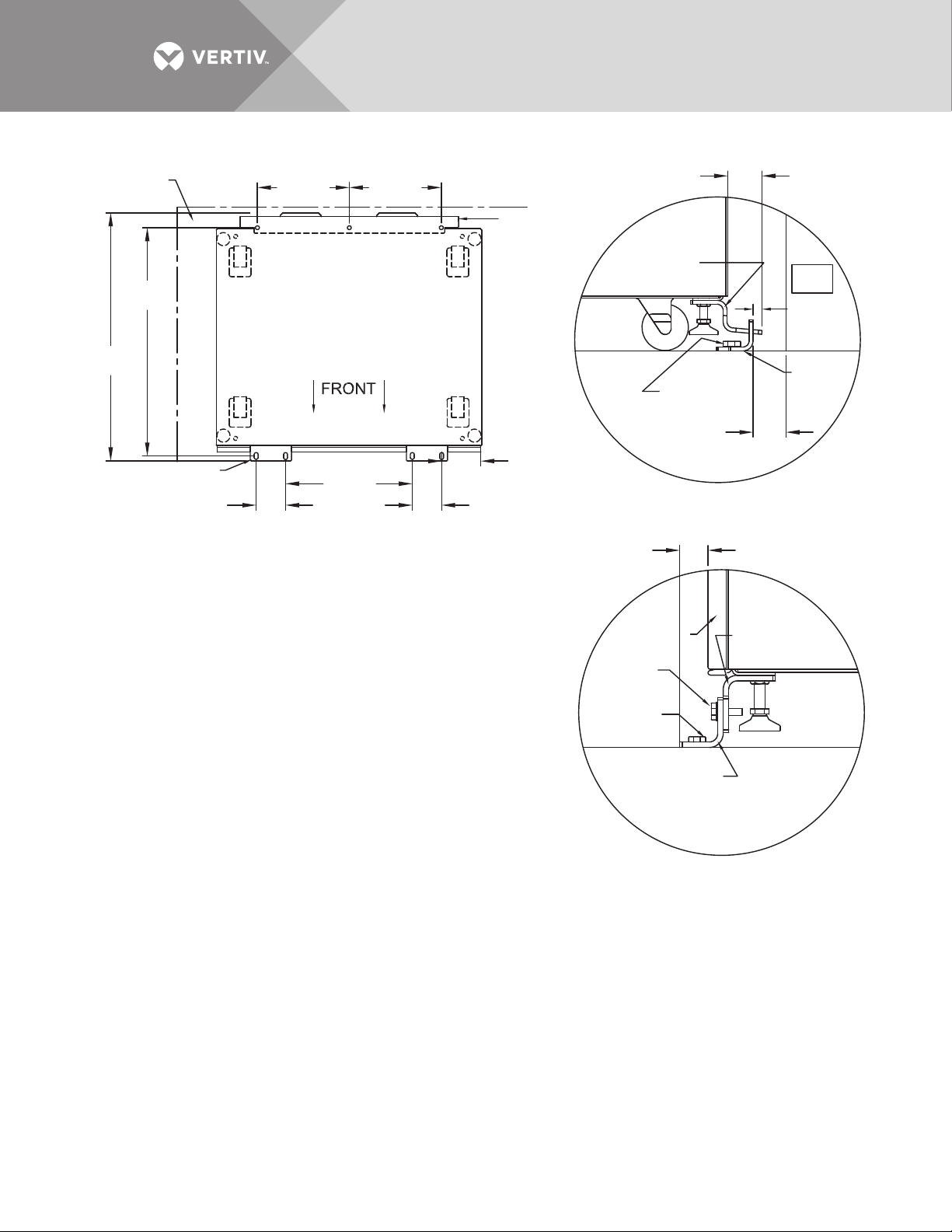
Figure 11 Seismic anchor drawing: 400 – 600 amp Liebert STS2
See Note 7
for spacing
(832mm)
35.72"
(907mm)
32.75"
Front Floor
Bracket
Side Wall
4.2"
(107mm)
13.2"
(335mm)
Front
(462mm)
TOP
18.2"
13.2"
(335mm)
Back Wall
Rear Floor
Bracket
See Note 2
for spacing
(146mm)
4.2"
(107mm)
System Seismic Anchoring, Figure 1
NOTES
1. Recommended floor anchor: 1/2" ITW Ramset/Red Head self-drilling
anchor; ICBO #ER-1372 or equivalent (not supplied). Follow
manufacturer's instructions.
2. Position rear floor brackets on floor at least 0.75" (19mm) from back
wall. Mark location and drill holes (Figure 1) to a minimum depth
of 4.12" (104.7mm) into the concrete.
3. Install rear cabinet base bracket (Figure 2) to existing holes on the
underside of the unit with tabs facing the back wall. Use supplied
hardware and torque to 365 lb./in. (41.2Nm). Loosen leveling bolt
locking nut and tighten after the bracket is secured.
4. Install the front cabinet base to existing holes on the underside of
the unit with the bent flange facing front. Use the supplied hardware
and torque to 365 lb./in. (41.2Nm). Loosen leveling bolt locking nut and
tighten after the bracket is secured.
5. Move the cabinet into position with the rear tabs into the slots of the
floor bracket. The tabs must extend at least 1/2" (12.7mm) through
the floor bracket (Figure 2). Then attach the front floor brackets to the
front cabinet base bracket, but do not fully tighten the hardware.
6. Mark the hole locations and remove the brackets. Drill and install the floor
brackets. The unit's door can be removed for better access. Reinstall the
front floor brackets to the front cabinet brackets with the supplied hardware
and torque to 235 lb./in. 26.5Nm); see Figure 3.
7. If side walls are present, 5" (127mm) minimum distance from either side
wall is required.
8. Rear and front floor brackets and the rear and front cabinet base brackets
are 1010 steel and approximately 1/4" (6.4mm) thick.
5.75"
Rear Cabinet
Base Bracket
Floor Line
Floor Anchor
Hardware
(Field-Supplied)
Front Door
of Cabinet
Hardware
Supplied
Floor Anchor
Hardware
(Field-Supplied)
Front Floor
Bracket
PS211405
Rev. 1
2.26"
(57.5mm)
Back
Wall
1/2"
(12.5mm)
Approx.
Rear Floor
Bracket
3/4"
(19mm)
Figure 2
1.364"
(34.6mm)
Front Cabinet
Base Bracket
Floor Line
Figure 3
Vertiv™ | Liebert® STS2™ 100-1000A, 50/60Hz User Manual | Rev. 12 | 11/2017 24
Page 33
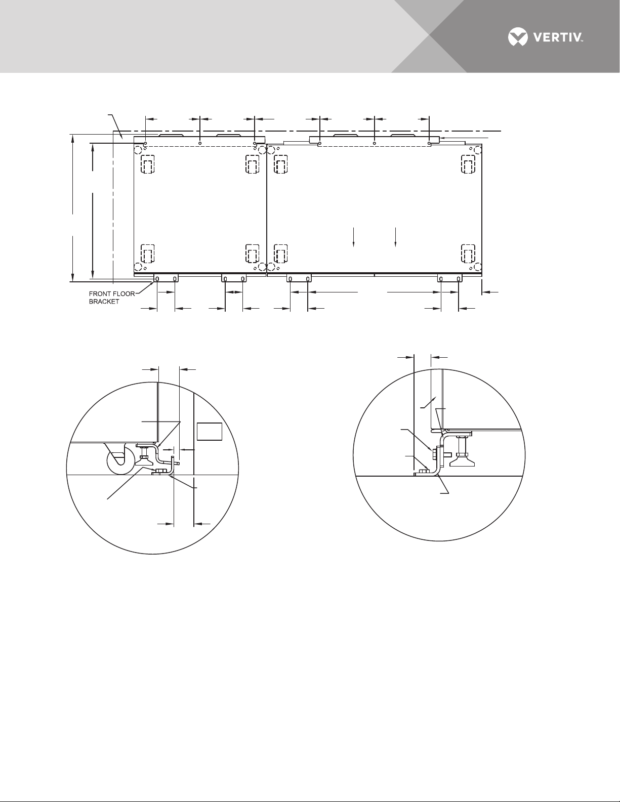
Figure 12 Seismic anchor drawing: 800 – 1000 amp Liebert STS2
See Note 7
for spacing
32.75"
(832mm)
35.72"
(907mm)
Side Wall
13.2"
(335mm)
4.2"
(107mm)
(335mm)
12.2"
(310mm)
13.2"
4.2"
(107mm)
(396mm)
11. 4"
(298mm)
15.6"
4.2"
(107mm)
13.2"
(335mm)
TOP
System Seismic Anchoring, Figure 1
2.26"
(57.5mm)
Front
32.2"
(817mm)
13.2"
(335mm)
Back Wall
4.2"
(107mm)
1.364"
(34.6mm)
Rear Floor
Bracket
See Note 2
for spacing
5.7"
(144mm)
Rear Cabinet
Base Bracket
Floor Line
Floor Anchor
Hardware
(Field-Supplied)
(19mm)
Back
Wall
1/2"
(12.5mm)
Approx.
Rear Floor
Bracket
3/4"
Figure 2
NOTES
1. Recommended floor anchor: 1/2" ITW Ramset/Red Head
self-drilling anchor; ICBO #ER-1372 or equivalent (not
supplied. Follow manufacturer's instructions.
2. Position rear floor brackets on floor at least 0.75" (19mm)
from back wall. Mark location and drill holes (Figure 1) to
a minimum depty of 4.12" (104.7mm) into the concrete.
3. Install rear cabinet base bracket (Figure 2) to existing holes
on the underside of the unit with tabs facing the back wall.
Use supplied hardware and torque to 365 lb./in. (41.2Nm).
Loosen leveling bolt locking nut and tighten after the
bracket is secured.
4. Install the front cabinet base (Figure 3) to existing holes
on the underside of the unit with the bent flange facing front.
Use the supplied hardware and torque to
365 lb./in. (41.2Nm). Loosen leveling bolt locking nut and
tighten after the bracket is secured.
Front Door
of Cabinet
Hardware
Supplied
Floor Anchor
Hardware
(Field-Supplied)
Front Floor
Bracket
Front Cabinet
Base Bracket
Floor Line
Figure 3
5. Move the cabinet into position with the rear tabs into the
slots of the floor bracket. The tabs must extend at least
1/2" (12.7mm) through the floor bracket (Figure 2).
Then attach the front floor brackets to the front cabinet
base bracket, but do not fully tighten the hardware.
6. Mark the hole locations and remove the brackets. Drill
and install the floor brackets. The unit door can be removed
for better access. Reinstall the front floor brackets to the
front cabinet brackets with the supplied hardware and
torque to 235 lb./in. 26.5Nm), see Figure 3.
7. If side walls are present, minimum distance from either
side wall is required.
8. Rear and front floor brackets and the rear and front cabinet
base brackets are 1010 steel and approximately 1/4"
(6.4mm) thick.
PS211805
Rev. 1
Vertiv™ | Liebert® STS2™ 100-1000A, 50/60Hz User Manual | Rev. 12 | 11/2017 25
Page 34
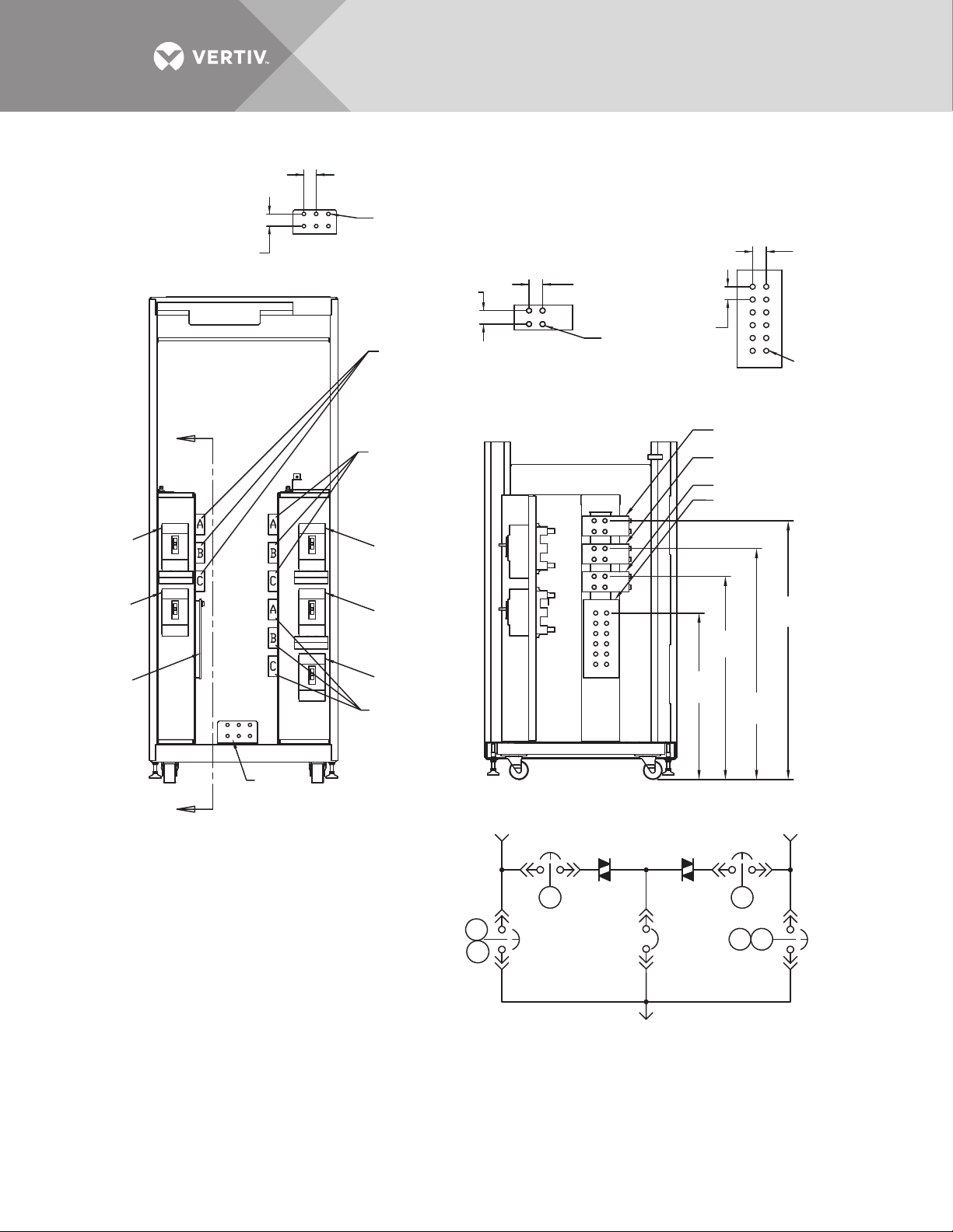
Figure 13 Electrical field connections drawing: 100 – 250 amp Liebert STS2 with single output breaker
1.75"
(44.4mm)
1.75"
(44.4mm)
1.75"
(44.4mm)
1/2" - 13
PEM Nut
1/2" - 13
PEM Nut
1.77" (45mm)
Typ.
1.75"
(44mm)
Typ.
Source 1 Input
ØA, ØB, ØC
Source 2 Input
ØA, ØB, ØC
System Output
ØA, ØB, ØC
Source 1
Source 1 Input ØC
Source 1 Input ØB
Source 1 Input ØA
Source 2
System Output
ONE-LINE DIAGRAM
INPUT/OUTPUT BUS
Right Side
GROUND BUS
Front
FRONT
(Panels Removed)
CB1
CB1
CB4
A
CB4
CB3
CB2
CB2
CB5
CB3
CB5
K1
K1
K2
K2
K3
K3
PS212100
Rev. 4
NOTES
1. Top and bottom cable entry available through
removable access plates. Remove, punch to suit
conduit size and replace.
2. Control wiring and power wiring must be run in
separate conduit. Output cables should be run in
a separate conduit from input cables.
3. Aluminum and copper-clad aluminum cables
are not recommended.
4. All wiring must be in accordance with national and
local electrical codes.
5. Hardware kit is supplied for input, output, neutral
and ground cable connections. Kit includes 1/2" bolts,
washers and nuts for connecting cables to the busbars.
6. The torque requirement for 1/2" - 13 PEM nuts is
428 in./lb (48Nm).
Front
NEUTRAL BUS
Right Side
Neutral
Bus
Ground
Bus
SECTION A-A
Side View
Ø 0.51"
(13mm)
Typ.
32.2"
(818mm)
42"
(165mm)
Typical
36.7"
(932mm)
26.4"
(671mm)
41.1"
(1044mm)
A
Neutral Bus
Vertiv™ | Liebert® STS2™ 100-1000A, 50/60Hz User Manual | Rev. 12 | 11/2017 26
Page 35
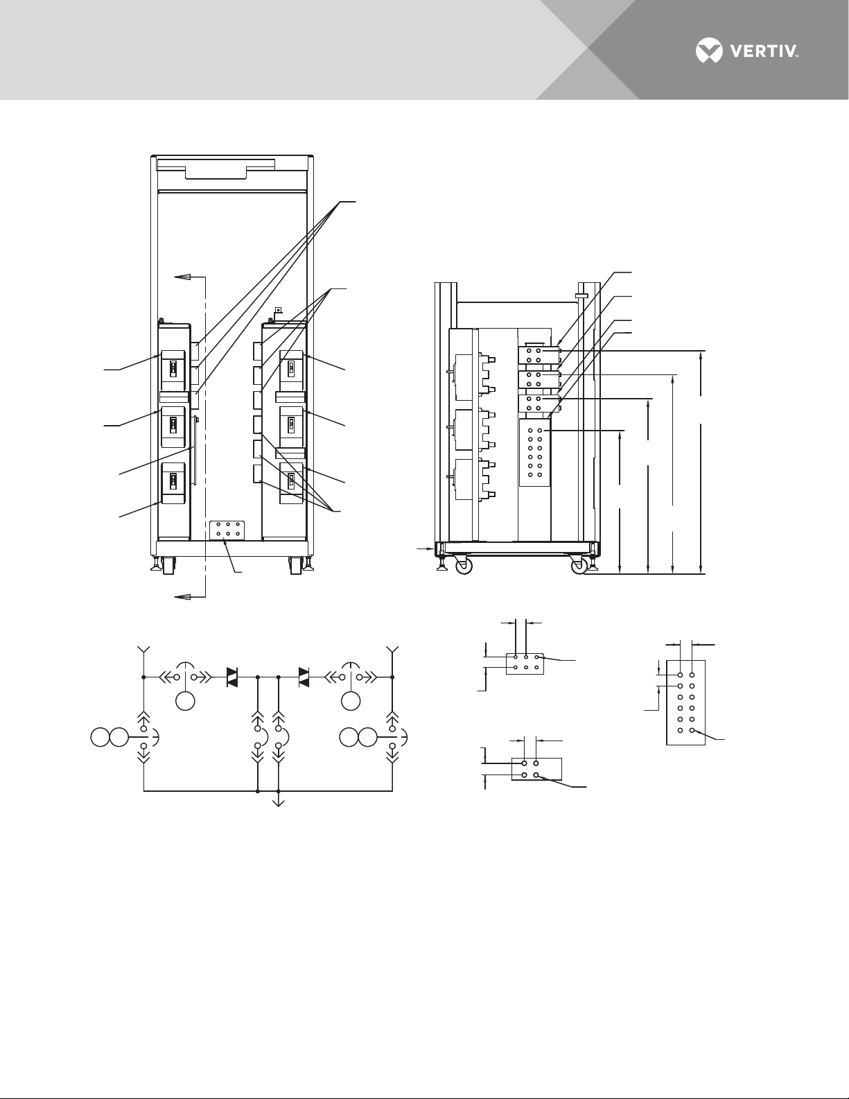
Figure 14 Electrical field connections drawing: 100 – 250 amp Liebert STS2 with dual output breakers
1/2" - 13
PEM Nut
1/2" - 13
PEM Nut
1.77"
(45mm) Typ.
1.65"
(42mm)
Typ.
1.75"
(44.4mm)
1.75"
(44.4mm)
1.75"
(44.4mm)
1.75"
(44.4mm)
Ground
Bus
Neutral Bus
Neutral
Bus
Source 1 Input ØA
Source 1 Input
ØA, ØB, ØC
Source 2 Input
ØA, ØB, ØC
System Output
ØA, ØB, ØC
Source 1
Source 1 Input ØB
Source 1 Input ØC
Source 2
System Output
ONE-LINE DIAGRAM
INPUT/OUTPUT BUS
Right Side
GROUND BUS
Front
FRONT
(Panels Removed)
CB1
CB1
CB4
CB4
CB3
CB3A
CB2
CB2
CB5
CB3
Front
CB3A
CB5
K1
K1
K2
K2
K3
K3
PS212101
Rev. 5
NOTES
1. Top and bottom cable entry available through removable access plates.
Remove, punch to suit conduit size and replace.
2. Control wiring and power wiring must be run in separate conduit.
Output cables should be run in a separate conduit from input cables.
3. Aluminum and copper-clad cables are not recommended.
4. All wiring must be in accordance with national and local electrical codes.
5. Hardware kit is supplied for input, output, neutral and ground cable
connections. Kit includes 1/2" bolts, washers and nuts for connecting
cables to the busbars.
6. The torque requirement for 1/2" - 13 PEM nuts is 428 in./lb (48Nm).
A
NEUTRAL BUS
Right Side
SECTION A-A
Side View
Ø 0.51"
(13mm)
Typ.
41.1"
(1044mm)
36.7"
(932mm)
32.2"
(818mm)
26.4"
(671mm)
A
A
B
C
A
B
C
A
B
C
Vertiv™ | Liebert® STS2™ 100-1000A, 50/60Hz User Manual | Rev. 12 | 11/2017 27
Page 36
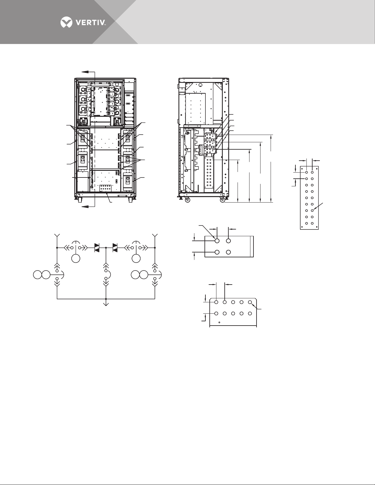
1/2" - 13
PEM Nut
1/2" - 13
PEM Nut
1.75"
(44.4mm)
Typ.
1.3"
(33mm)
Typ.
1.75"
(44.4mm)
1.75"
(44.4mm)
1.75"
(44.4mm)
1.97"
(50mm)
Ground
Bus
Neutral Bus
Neutral
Bus
Source 1 Input ØA
Source 1 Input
ØA, ØB, ØC
Source 2 Input
ØA, ØB, ØC
System Output
ØA, ØB, ØC
Source 1
Source 1 Input ØB
Source 1 Input ØC
Source 2
System Output
ONE-LINE DIAGRAM
INPUT/OUTPUT BUS
Right Side
GROUND BUS
Front
FRONT
(Panels Removed)
CB1
CB1
CB4
CB4
CB3
CB2
CB2
CB5
CB3
CB5
K1
K1
K2
K2
K3
K3
PS212400
Rev. 4
NOTES
1. Top and bottom cable entry available through removable access plates.
Remove, punch to suit conduit size and replace.
2. Control wiring and power wiring must be run in separate conduit.
Output cables should be run in a separate conduit from input cables.
3. Aluminum and copper-clad cables are not recommended.
4. All wiring must be in accordance with national and local electrical codes.
5. Hardware kit is supplied for input, output, neutral and ground cable
connections. Kit includes 1/2" bolts, washers and nuts for connecting
cables to the busbars.
6. The torque requirement for 1/2" - 13 PEM nuts is 428 in./lb (48Nm).
A
NEUTRAL BUS
Right Side
SECTION A-A
Side View
Ø 0.51"
(13mm)
Typ.
41.7"
(1060mm)
37.2"
(946mm)
32.7"
(832mm)
26.3"
(668mm)
A
Figure 15 Electrical field connections drawing: 400 – 600 amp Liebert STS2 with single output breaker
Vertiv™ | Liebert® STS2™ 100-1000A, 50/60Hz User Manual | Rev. 12 | 11/2017 28
Page 37
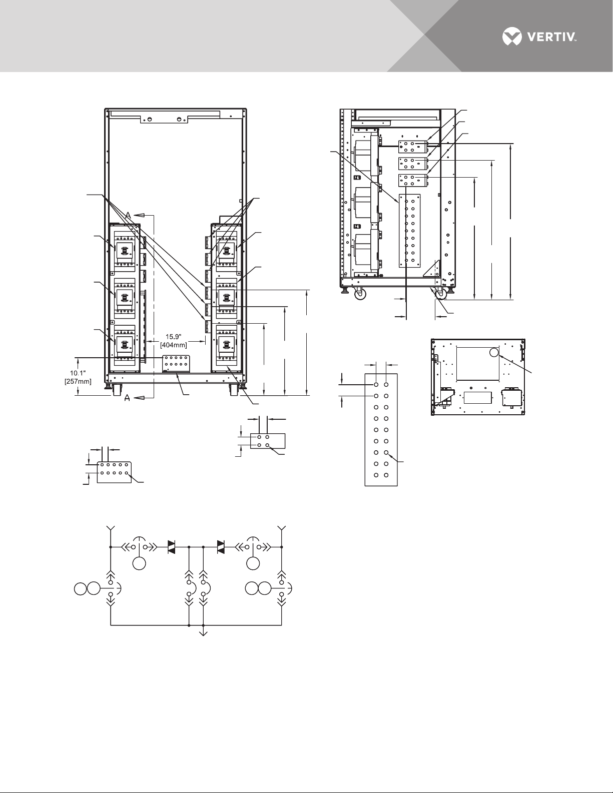
Figure 16 Electrical field connections drawing: 400 – 600 amp Liebert STS2 with dual output breakers
Neutral
Bus
Source 1 Input Ø A
Source 1 Input Ø B
Source 1 Input Ø C
Source 2
Output
Ø A, Ø B, Ø C
CB1
CB4
CB3A
1.75"
(44mm)
GROUND BUS
K3
K2
Source 2 Input
Ø A, Ø B, Ø C
CB2
CB5
23.8"
(605mm)
19.3"
(490mm)
Ground
Bus
CB3
FRONT
(Panels Removed)
1.3" (33mm)
Typical
Ø 0.51"
(13mm) Typical
Source 1 Source 2
CB1
K1
CB4
CB3
SYSTEM OUTPUT
One-Line Diagram
1.75"
(44mm)
INPUT/OUTPUT BUS
Right Side
CB2
K2
CB3A
K1
(44mm)
1/2" - 13
PEM Nut
K3
PS212401
Rev. 4
Front
7.8"
(198mm)
28.3"
(719mm)
7.6"
(193mm)
SECTION A-A
Side View
1.75"
(44mm)
1.97" (50mm)
1.75"
Top View Looking Down
1/2" - 13
PEM Nut
NEUTRAL BUS
Right Side
NOTES
1. Top and bottom cable entry available through
removable access plates.
Remove, punch to suit conduit size and replace.
2. Control wiring and power wiring must be run in
separate conduit. Output cables should be run
in a separate conduit from input cables.
CB5
3. Aluminum and copper-clad aluminum cables
are not recommended.
4. All wiring must be in accordance with national
and local electrical codes.
5. Hardware kit is supplied for input, output, neutral
and ground cable connections. Kit includes
1/2" bolts, washers and nuts for connecting
cables to the busbars.
6. The torque requirement for 1/2" - 13 PEM nuts
is 428 in./lb (48Nm).
32.9"
(836mm)
37.4"
(950mm)
See Detail A
DETAIL A
41.9"
(1064mm)
Ø 3.5"
(89mm)
Hole
Vertiv™ | Liebert® STS2™ 100-1000A, 50/60Hz User Manual | Rev. 12 | 11/2017 29
Page 38
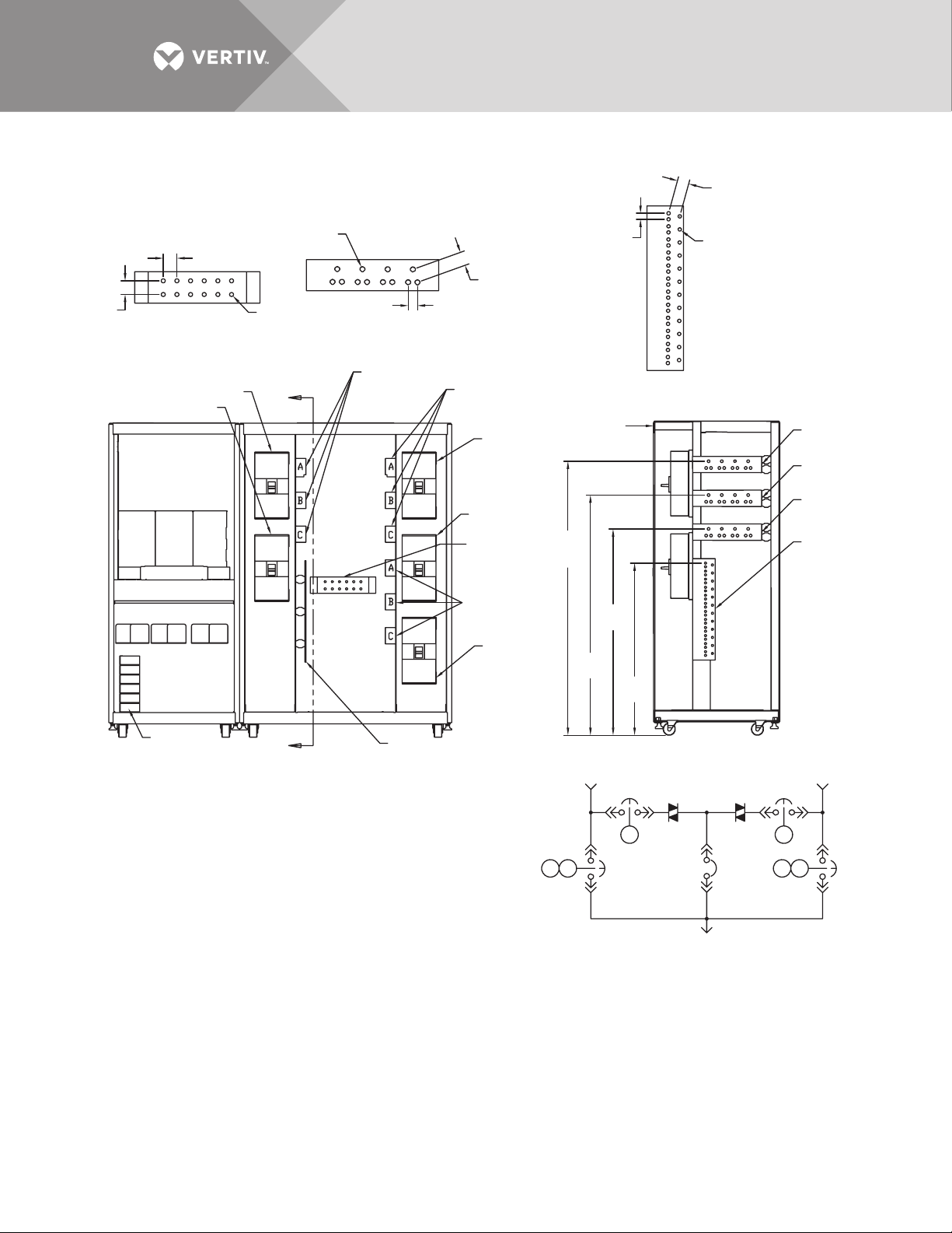
1.75"
(44mm)
Typ.
1.75" (44mm)
Typ.
1/2" - 13
PEM Nut
1.75" (44mm)
Typ.
1.75"
(44mm)
Typ.
0.91"
(23mm)
Typ.
1.2" (30mm)
Typ.
Ground
Bus
Neutral
Bus
Source 1
Input ØA
Source 1 Input
ØA, ØB, ØC
Source 2 Input
ØA, ØB, ØC
Source Output
ØA, ØB, ØC
Source 1
Source 1
Input ØB
Source 1
Input ØC
Source 1
Input ØC
Source 2
System Output
ONE-LINE DIAGRAM
INPUT/OUTPUT BUS
Right Side
GROUND BUS
Front
FRONT
(Panels Removed)
CB1
CB1
CB4
CB4
CB3
CB2
CB2
CB5
CB3
CB5
K1
K1
K2
K2
K3
K3
PS212800
Rev. 6
NOTES
1. Top and bottom cable entry available through removable access plates.
Remove, punch to suit conduit size and replace.
2. Control wiring and power wiring must be run in separate conduit.
Output cables should be run in a separate conduit from input cables.
3. Use copper or aluminum wire (Cu-Al, Al-Cu) or equivalent.
4. All wiring must be in accordance with national and local electrical codes.
5. Hardware kit is supplied for input, output, neutral and ground cable
connections. Kit includes 1/2" bolts, washers and nuts for connecting
cables to the busbars.
6. The torque requirement for 1/2" - 13 PEM nuts is 428 in./lb (48Nm).
A
Front
NEUTRAL BUS
Right Side
SECTION A-A
Side View
Ø 0.51"
(13mm)
Typ.
Ø 0.51"
(13mm)
Typ.
67.2"
(1707)
50.6"
(1285)
58.9"
(1488)
42.2"
(1072)
A
Option Box
Refer to
PS213800
Figure 17 Electrical field connections drawing: 800 – 1000 amp Liebert STS2 with single output breaker
Vertiv™ | Liebert® STS2™ 100-1000A, 50/60Hz User Manual | Rev. 12 | 11/2017 30
Page 39
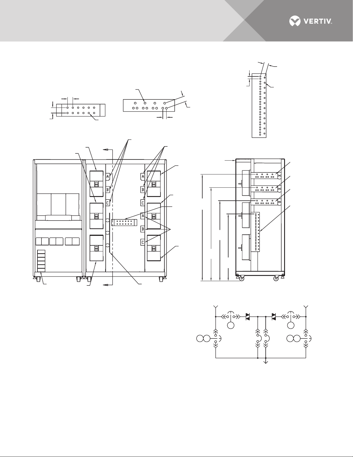
1.75"
(44mm)
Typ.
1.75" (44mm)
Typ.
1/2" - 13
PEM Nut
1.75" (44mm)
Typ.
1.75" (44mm)
Typ.
1.75"
(44mm)
Typ.
0.91"
(23mm)
Typ.
1.2" (30mm)
Typ.
Ground
Bus
Neutral
Bus
Source 1
Input ØA
Source 1 Input
ØA, ØB, ØC
Source 2 Input
ØA, ØB, ØC
Source Output
ØA, ØB, ØC
Source 1
Source 1
Input ØB
Source 1
Input ØC
Source 1
Input ØC
Source 2
System Output
ONE-LINE DIAGRAM
INPUT/OUTPUT BUS
Right Side
GROUND BUS
Front
FRONT
(Panels Removed)
CB1
CB1
CB4
CB4
CB3
CB2
CB2
CB5
CB3
CB3A
CB3A
CB3A
CB5
K1
K1
K2
K2
K3
K3
PS212801
Rev. 7
NOTES
1. Top and bottom cable entry available through removable access plates.
Remove, punch to suit conduit size and replace.
2. Control wiring and power wiring must be run in separate conduit.
Output cables should be run in a separate conduit from input cables.
3. Use copper or aluminum wire (Cu-Al, Al-Cu) or equivalent.
4. All wiring must be in accordance with national and local electrical codes.
5. Hardware kit is supplied for input, output, neutral and ground cable
connections. Kit includes 1/2" bolts, washers and nuts for connecting
cables to the busbars.
6. The torque requirement for 1/2" - 13 PEM nuts is 428 in./lb (48Nm).
A
Front
NEUTRAL BUS
Right Side
SECTION A-A
Side View
Ø 0.51"
(13mm)
Typ.
Ø 0.51"
(13mm)
Typ.
67.2"
(1707)
50.6"
(1285)
58.9"
(1488)
42.2"
(1072)
A
Option Box
Refer to
PS213800
Figure 18 Electrical field connections: 800 – 1000 amp Liebert STS2 with dual output breakers
Vertiv™ | Liebert® STS2™ 100-1000A, 50/60Hz User Manual | Rev. 12 | 11/2017 31
Page 40
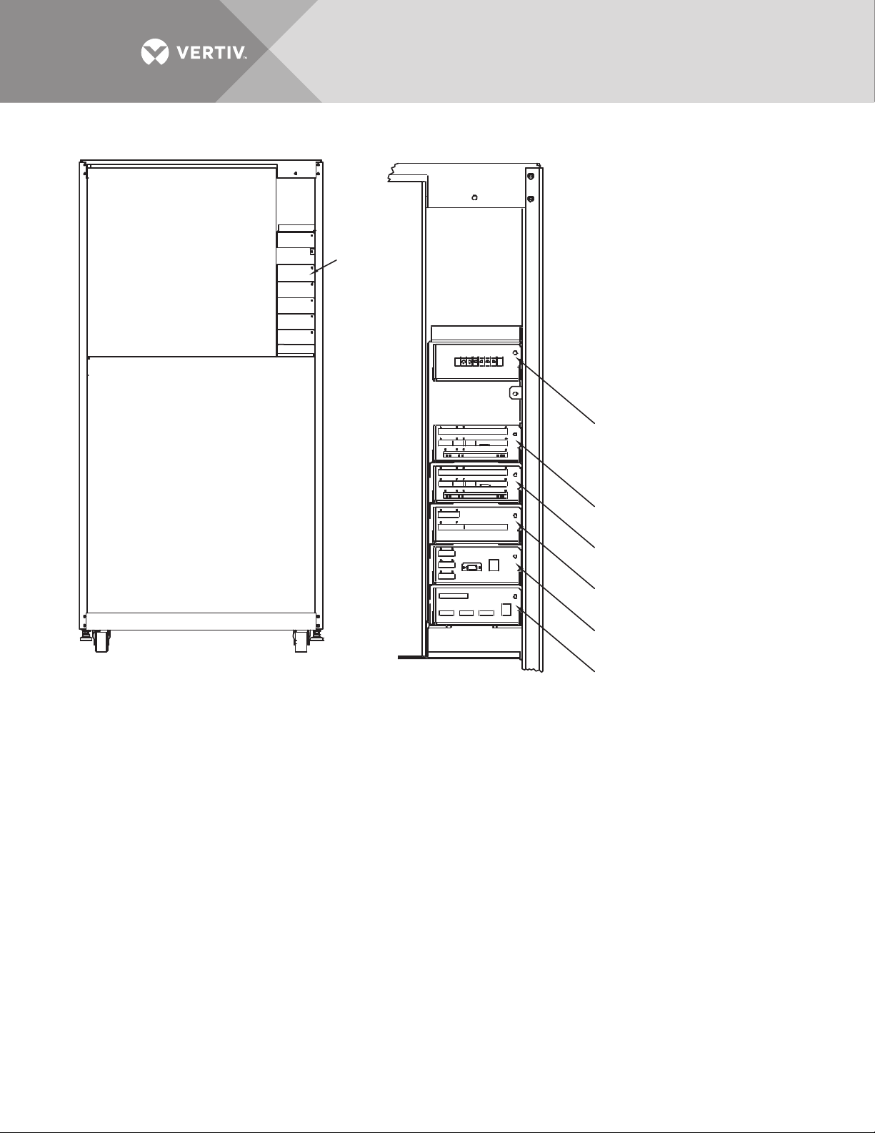
Figure 19 Control connection location diagram: 100 – 600 amp Liebert STS2
CONTROL WIRING
Front; Door Not Shown
PS213000
Rev. 2
NOTES
1. Typical options are shown.
2. A maximum of two programmable
relay boards can be used
Remote Source
Select (Option)
See Option
Location
Detail
Programmable Relay
Board (Option); See Note 2
Programmable Relay
Board (Option); See Note 2
Input Contact Isolator Board
(Option) or Programmable Relay
Board (Option); See Note 2
Comms Board for Liebert
SiteScan
Network Interface
Card (Option)
OPTION LOCATION DETAIL
Vertiv™ | Liebert® STS2™ 100-1000A, 50/60Hz User Manual | Rev. 12 | 11/2017 32
Page 41
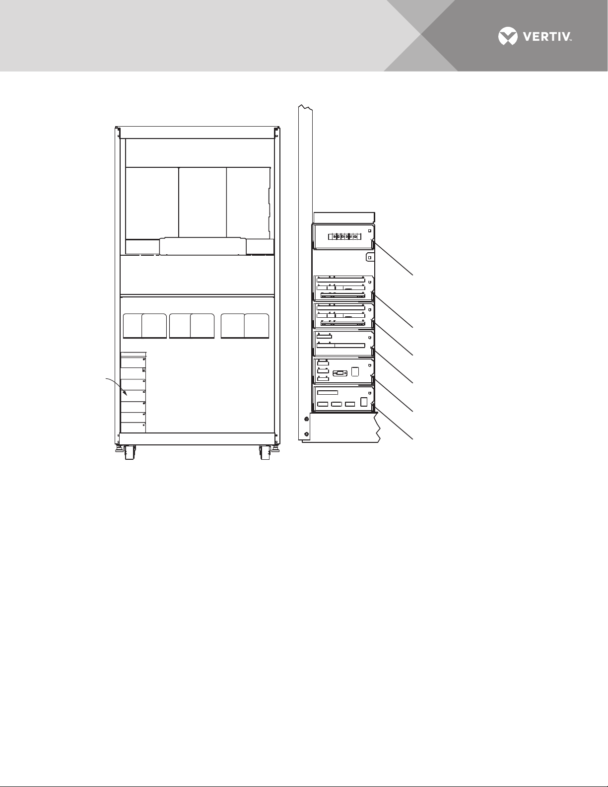
Figure 20 Control connection location diagram: 800 – 1000 amp Liebert STS2
See Option
Location
Detail
OPTION
CONTROL WIRING
Front; Door Not Shown
LOCATION DETAIL
NOTES
1. Typical options are shown.
2. A maximum of two programmable
relay boards can be used
Remote source
Select (Option)
Programmable Relay
Board (Option); See Note 2
Programmable Relay
Board (Option); See Note 2
Input Contact Isolator Board
(Option) or Programmable Relay
Board (Option); See Note 2
Network Interface
Card (Option)
Comms Board for Liebert
SiteScan
PS213800
Rev. 2
Vertiv™ | Liebert® STS2™ 100-1000A, 50/60Hz User Manual | Rev. 12 | 11/2017 33
Page 42
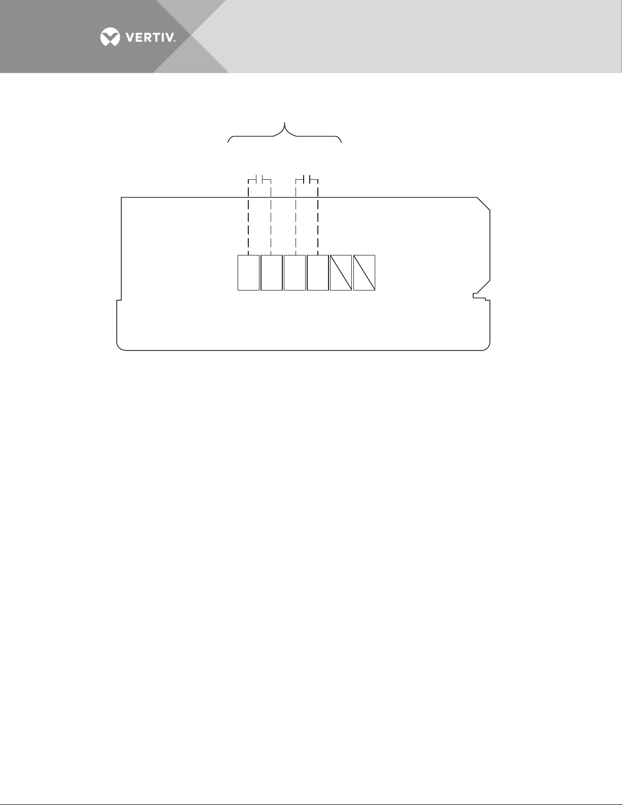
Figure 21 Control wiring for remote source selection option
PS213007
Rev. 2
REMOTE SOURCE SELECTION
See Note 1
Source1
Preferred
Source 2
Preferred
TB50
S1 S2GND GND
123456
NOTES
1. Customer-provided normally open dry contacts. Rating 10mA at 30 VDC.
2. Maximum cable length 500 ft. (152m) with 16 AWG, 300V minimum,
flexible stranded cable.
3. All control wiring, by others, must be run separately from power wiring.
Control wiring runs should not be combined in the same conduit.
4. Refer to Static Transfer Switch control connection diagram for location
of remote source selection option. All wiring must be in accordance
with national and local electrical codes.
Vertiv™ | Liebert® STS2™ 100-1000A, 50/60Hz User Manual | Rev. 12 | 11/2017 34
Page 43
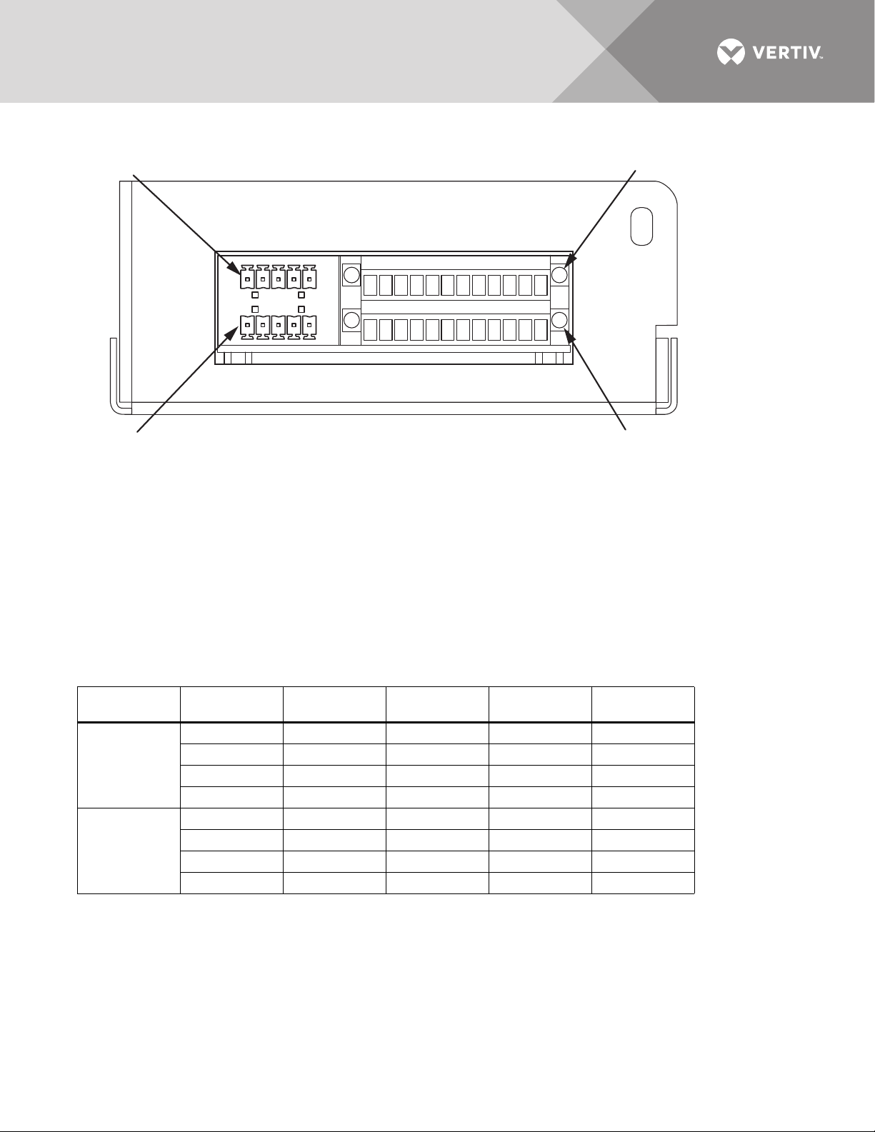
Figure 22 Control wiring for the programmable relay board option
P99
P66
PS213001
Rev. 3
J71
J72
PROGRAMMABLE RELAY BOARD
NOTES
1. Customer control wiring connection points are Terminal
Blocks 1 through 12.
2. Programmable relay board option includes eight signal
channels with one Form-C dry contact per channel. See
table. C = Common; NC = Normally Closed;
NO = Normally Open
3. Refer to accompanying text to configure the programmable
relay board option.
4. All control wiring (by others) must be run separately from
power wiring. Control wiring runs should not be combined
in the same conduit.
5. Refer to static switch control connection diagram
for location of program relay board option.
6. Contact ratings: 1A @ 30VDC, 400mA @ 125VAC.
7. Maximum cable length 500 ft. (152m) with #16AWG
flexible stranded cable.
8. All wiring must be in accordance with national and
local electrical codes.
132465798101211
132465798101211
Ter mi na l
Block Channel Pin # Common
Ch1 1 - 3 1 2 3
J71
J72
Ch2 4 - 6 4 5 6
Ch3 7 - 9 7 8 9
Ch4 10 - 12 10 11 12
Ch5 1 - 3 1 2 3
Ch6 4 - 6 4 5 6
Ch7 7 - 9 7 8 9
Ch8 10 - 12 10 11 12
Vertiv™ | Liebert® STS2™ 100-1000A, 50/60Hz User Manual | Rev. 12 | 11/2017 35
Normally
Closed
Normally
Open
Page 44
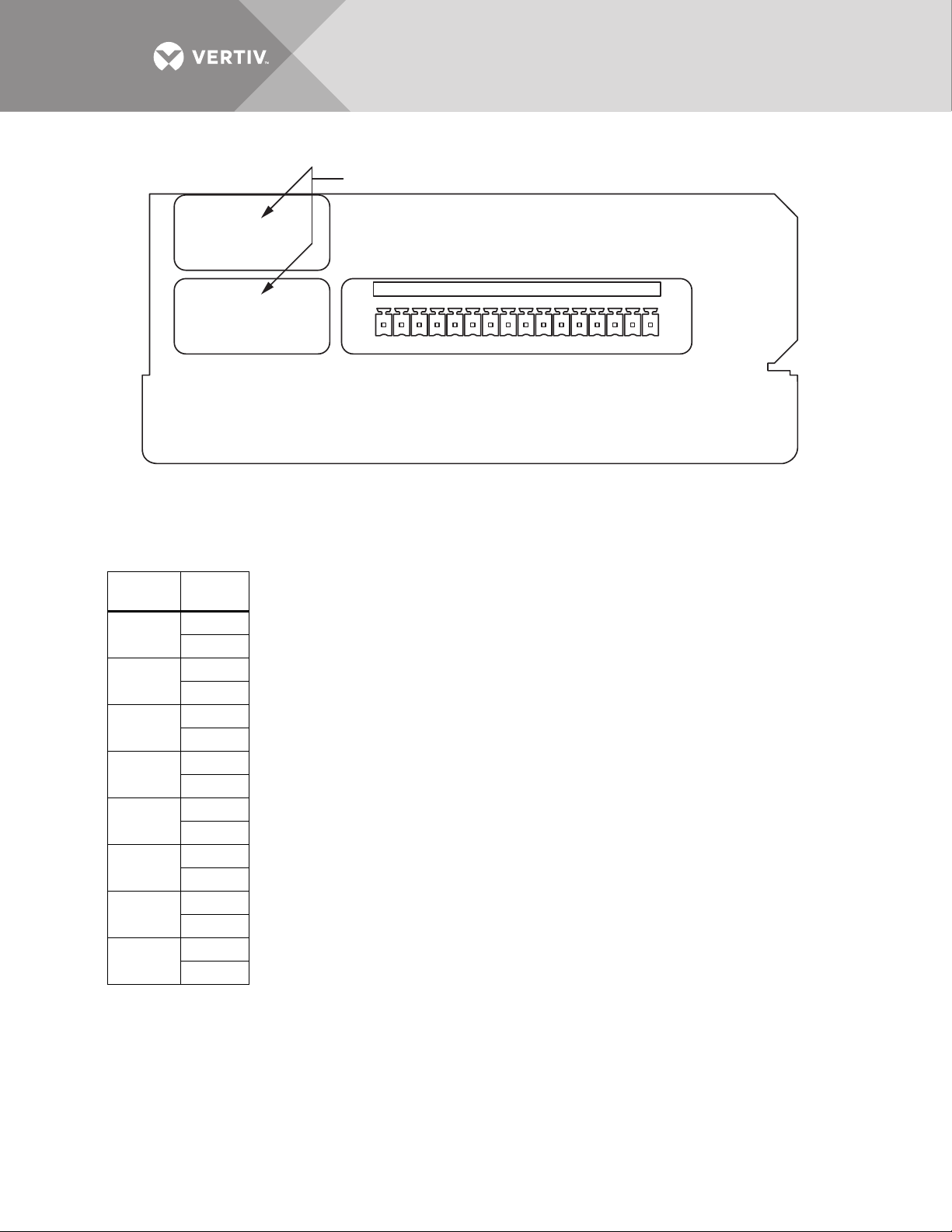
Figure 23 Control wiring for the input contact isolator board option
21534 67 1411981012131516
No Customer Connection
INPUT CONTACT ISOLATOR BOARD
02-810012-XX
J51
PS213002
Rev. 3
NOTES:
1. Customer control wiring connection points are Terminals 1 through 16
(see Table J51).
2. Customer-provided, normally open, dry contacts for user alarm messages.
3. Refer to installation, operation and maintenance manual for configuring the Input Contact
Isolator board option.
4. All control wiring (by others) must be run separate from power wiring. Control wiring runs
should not be combined in the same conduit.
5. Refer to static transfer switch control connection diagram (Figure 19 or 20) for location of Input
Contact Isolator board option.
6. Signal voltage: 100mA @ 12VDC.
7. Maximum cable length 500 ft. (152 m) with #16 AWG flexible, stranded cable.
8. All wiring must be in accordance with national and local electrical codes.
9. When the Transfer Inhibit option is supplied, connect a N.O. dry contact (customer-supplied) to
Input Contact 8 (Pins 15 and 16). When the customer contact closes, transfers will be inhibited
as long as the contact remains closed. Input Contact 8 is factory-set so no setup is required.
The Transfer Inhibit option prevents Input Contact 8 from being used for any other input.
Table J51
Input
Contact Pin No.
1
1
2
2
3
4
3
5
6
4
7
8
5
9
10
6
11
12
7
13
14
8
15
16
Vertiv™ | Liebert® STS2™ 100-1000A, 50/60Hz User Manual | Rev. 12 | 11/2017 36
Page 45
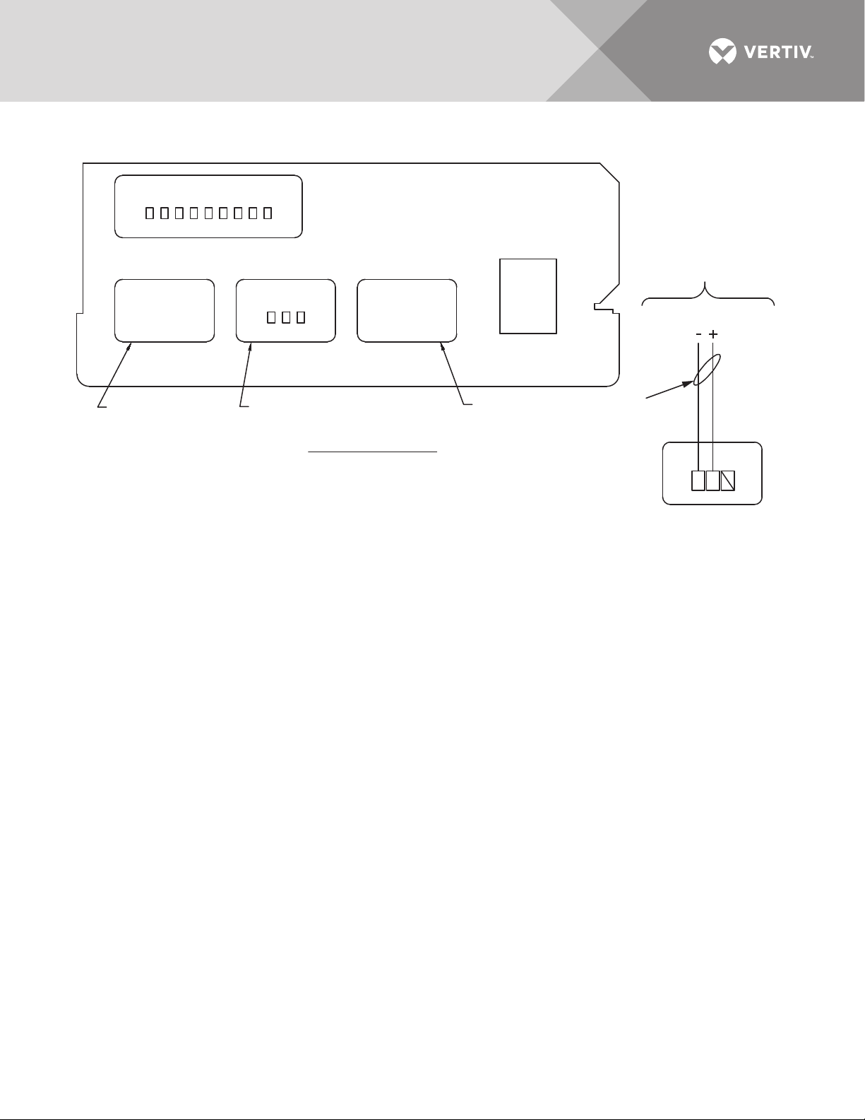
Figure 24 Control wiring for Comms board
TB51 TB55 TB56
J81
Customer-Supplied
Interconnecting
Cable to Liebert SiteScan
3
2
1
J1A
PS213003
Rev. 4
Notes
1. Maximum cable length 1000 ft. (300m)
with twisted pair cable #22 AWG 300V minimum.
2. All control wiring (by others) must be run
separate from power wiring. Control wiring
runs should not be combined in the same conduit.
3. Refer to control connection location diagram
of static transfer switch for location of Comms Board.
4. All wiring must be in accordance with national
and local electrical codes.
COMMS BOARD
02-810015-XX
TB55
Detail A
Liebert Sitescan
See Detail A
No Customer
Connection
No Customer
Connection
See
Note 1
Vertiv™ | Liebert® STS2™ 100-1000A, 50/60Hz User Manual | Rev. 12 | 11/2017 37
Page 46
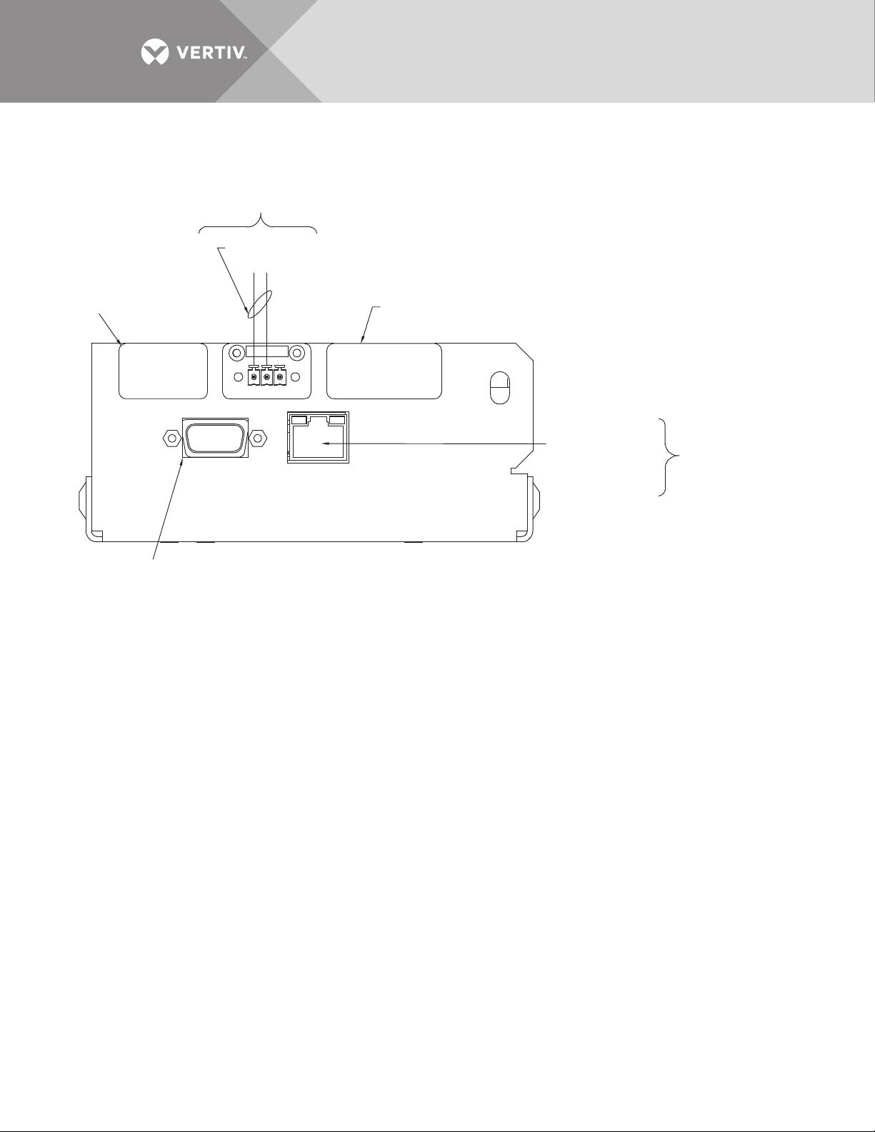
Figure 25 Control wiring for the Liebert IntelliSlot SNMP/Web/Modbus 485 card
+
-
1
23
Notes:
1. Wire size and type: 10/100 base-T ethernet cable with RJ-45 plug connector.
The length is limited by internet standards.
2. Maximum cable length 1000 feet (300 meters) with twisted pair cable #22 AWG
minimum. Signal voltage 5VDC, current 10mA.
3. Refer to the Liebert IntelliSlot Web/485 Card’s user manual for configuration details.
4. All control wiring (by others) must be run separate from power wiring. Control wiring runs
should not be combined in the same conduit.
5. Refer to control connection location diagram of static transfer switch for location of Liebert
IntelliSlot Web/485 card option.
6. All wiring must be in accordance with national and local electrical codes.
Customer-supplied
interconnection cable
to Modbus 485
See Note 2
No customer
connection
No customer
connection
RS-232 (DB-9 connector)
for setup only. Uses standard
computer serial port cable
Ethernet Network
RF-45 Connector
See Notes 1 and 2
Customer-Supplied
Interconnection
Cable:SNMP
(Web/HTTP)
TB3
TB2
TB1
DB-9
J3
PS213008
Rev. 3
Vertiv™ | Liebert® STS2™ 100-1000A, 50/60Hz User Manual | Rev. 12 | 11/2017 38
Page 47
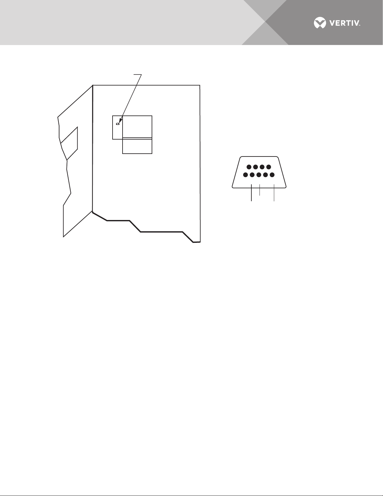
Figure 26 Control wiring for the RS-232 port
See Detail A
LCD
Notes:
1. RS-232 communication through
DB9 connector .
2. Connector accessible with front
door open . The cable must be
removed before closing door .
6789
12345
RXD
TXD
GND
DB9 Connector
Detail A
Front View
Upper Half of Unit
With Door Open
PS213006
Rev. 1
Vertiv™ | Liebert® STS2™ 100-1000A, 50/60Hz User Manual | Rev. 12 | 11/2017 39
Page 48
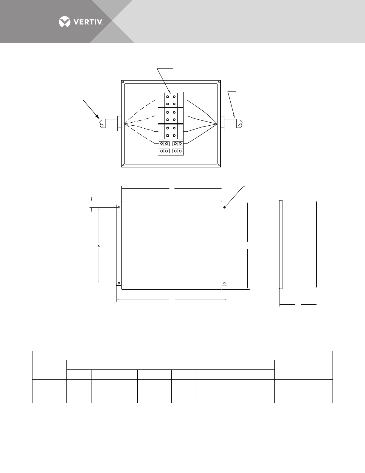
Figure 27 Outline drawing for input junction box
Recommended location for
customer connection of
input power raceway (by
others); 3-phase, 3-wire
plus ground
H
Power Terminal Block
A
B
C
G
INPUT JUNCTION BOX
B
Location of
factory-supplied
input power
cable assembly
G diameter
hole
A
D
C
1. Two junction boxes are supplied; one for each output.
2. Cable(s) to connect the junction box to the input busbars
are factory supplied. See electrical field connections
drawing for location.
3. Parallel cables are used on 400A and 600A units.
Input Junction Box
Dimensions, Inches (mm)
Rating
100A 16 (406) 14 (356) 6 (152) 17-1/2 (445) 12 (305) 16-3/4 (426) 5/16 (8) 1 (25) #6 AWG to #2/0 AWG
250A - 600A 16 (406) 30 (762) 6 (152) 33 (830) 10 (254) 32 (813) 7/16 (11) 3 (76)
PS211005
Rev. 0
Wire Size RangeABC D E F GH
(2) #6 AWG to (2)
500 kcmil
Vertiv™ | Liebert® STS2™ 100-1000A, 50/60Hz User Manual | Rev. 12 | 11/2017 40
Page 49
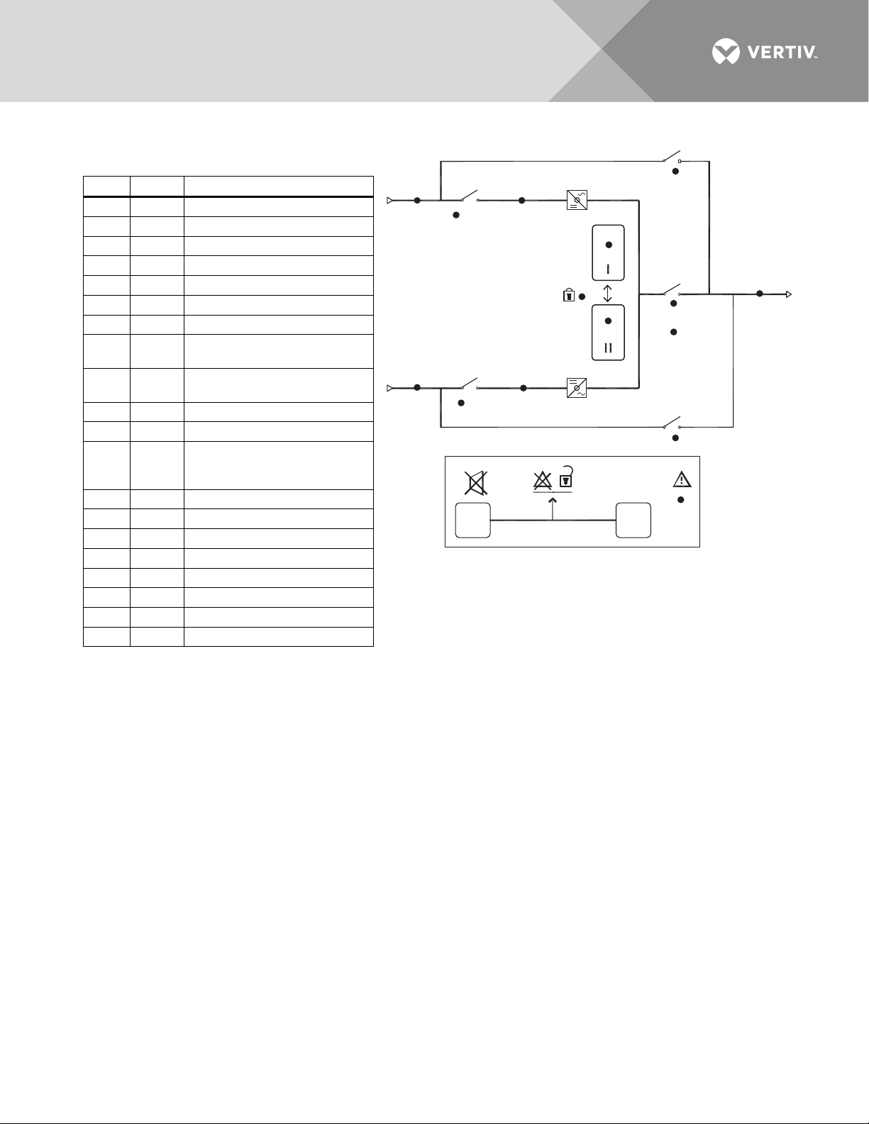
Figure 28 LED display
5
4
PS211002
Rev. N
~
~
~
~
~
A
1
1
C
E
H
G
3
3A
J
I
2
F
D
2
B
L
K
M
N
Symbol LED
Description
A Green Source 1 Power is Present
B Green Source 2 Power is Present
C Green Source 1 Within Tolerance
D Green Source 2 Within Tolerance
E Green Source 1 SCR’s On
F Green Source 2 SCR’s On
G Yellow Source Transfer Inhibited
HGreen
Push Button to Select Source 1 as
the Preferred Source
IGreen
Push Button to Select Source 2 as
the Preferred Source
J Green Output Power is Present
K — Alarm Silence Button
L—
Symbol to indicate the K and M must
be pushed at the same time to reset
alarm.
M — Alarm Reset Push Button
N Red Alarm Present
1 Green CB1 Closed
2 Green CB2 Closed
3 Green CB3 Closed
3A Green CB3A Closed
4 Yellow CB4 Closed
5 Yellow CB5 Closed
DISPLAY LEGEND
Vertiv™ | Liebert® STS2™ 100-1000A, 50/60Hz User Manual | Rev. 12 | 11/2017 41
Page 50
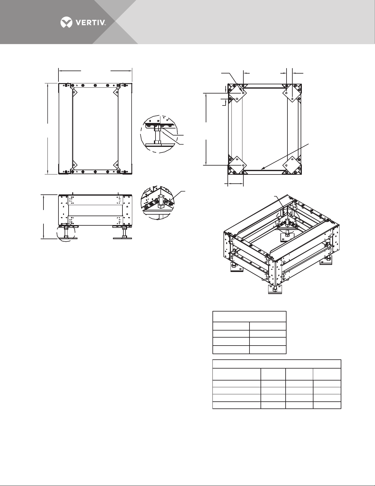
Figure 29 Installation drawing, seismic floor stand 100-250A
36.9"
(937mm)
See Height
Table
See
Detail A
29.9" (760mm)
TOP
FRONT
FOOT DETAIL A
FOOT DETAIL B
Align Foot Parallel
to Mounting Plate
as shown
2.47"
(63mm)
Typical
29.44"
(748mm)
Nut
Typical
Jam
Nut
(152mm)
Nut
Typical
17.48" (444mm)
Typical
6"
2.47"
(63mm)
Typical
Mounting
Plate
BOTTOM
See Detail B
INSTALLATION NOTES
1. Check all hardware for proper torque before installation.
2. Attach rear lower Liebert STS2 bracket on the floor stand using existing holes
with bent flange facing the front of the floor stand (see Figures 3 and 4 on
drawing PS215001). Use an M12-1.75x40mm cap screw, split lock washer
and torque to 53 ft./lb.
3. Loosen the Liebert STS2 adjustable leveling foot nuts (see Detail C, Drawing
PS215001). Install the rear upper Liebert STS2 bracket using existing holes
on the underside of the Liebert STS2 with tabs facing out (Figures 1 and 2,
Drawing PS215001). Install the front upper Liebert STS2 bracket using existing
holes on the underside of the Liebert STS2 with the bent flange facing to the front
(Figures 1 and 2, Drawing PS215001). Use an M12-1.75x40mm cap screw,
split lock washer and flat washer and torque to 53 ft. lb. Tighten the leveling foot nuts.
4. The floor stand can be installed next to a wall if needed; rear access is
not required. Install the floor stand with its feet oriented as shown in
the bottom view of Drawing PS215000. The floor stand must be level and all
feet must be touching the floor. Attach the floor stand feet using 1/2" x 4"
Red Head Trubolts expansion anchors (field-supplied); two per foot.
5. Roll the Liebert STS2 onto the floor stand so that the tabs on the rear upper
Liebert STS2 bracket fit into the slots on the rear lower Liebert STS2 bracket.
The tabs must extend at least 1/2" (12.9mm) through the floor stand bracket
(Figure 2, Drawing PS215002).
6. Install the lower front brackets (Figure 1, Detail A, Drawing PS215002). Attach
the bracket to the Liebert STS2 using M10-1.50x30mm cap screw, split lock washer
and flat washer. Torque to 31 ft./lb. Attach the bracket to the floor stand using
M12-1.75x40mm cap screw, split lock washer and flat washer. Torque to
53 ft./lb.
PS215000
Rev. 3
ISOMETRIC VIEW 250A FLOOR STAND
HARDWARE TORQUE
1.0" Nut 320 ft./lb.
M8 - 1.25
M10 - 1.5
M12 - 1.75
16 ft./lb.
31 ft./lb.
53 ft./lb.
HEIGHT TABLE
Floor Stand Part No. Height
523401G1 18.0" 19.25" 16.00"
523402G1 24.0" 25.25" 22.00"
523403G1 30.0" 31.25" 28.00"
523404G1 36.0" 37.25" 34.00"
Maximum
Height
Minimum
Height
Vertiv™ | Liebert® STS2™ 100-1000A, 50/60Hz User Manual | Rev. 12 | 11/2017 42
Page 51
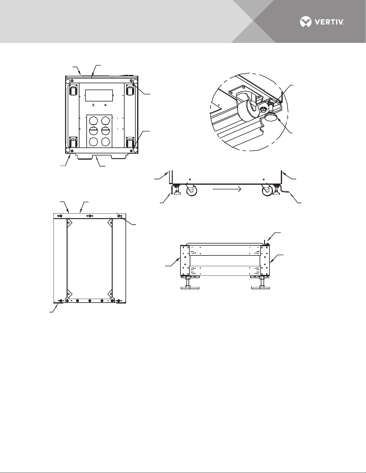
Figure 30 Installation drawing, seismic floor stand 100-250A
Front
Front Upper
Liebert STS2 Bracket
2 Places
Cap Screw M12-1.75x40mm
M12 Split Lock Washer
M12 Flat Washer
See Detail C
Leveling
Foot
Nut
Rear
Side
FIGURE 1
Rear Upper Liebert STS2 Bracket
Bottom of Liebert STS2
with Upper Brackets
Front
Rear
Top of Floor Stand
Rear Lower
Liebert STS2 Bracket
FIGURE 3
with Lower Rear Mounting Bracket
2 Places
Cap Screw M12-1.75x40mm
M12 Split Lock Washer
M12 Flat Washer
Front
Front Upper
Liebert STS2
Bracket
3 Places
Cap Screw M12-1.75x40mm
M12 Split Lock Washer
M12 Flat Washer
Front
Right Side of Liebert STS2
FIGURE 2
with Upper Brackets
FIGURE 4
Right Side of Floor Stand
with Lower Rear Mounting Bracket
See Drawings PS215000, PS215002 and PS215003
for details.
Leveling
Foot
DETAIL C
Rear
Rear Upper
Liebert STS2
Bracket
Rear Lower
Bracket
Rear
PS215001
Rev. 1
Vertiv™ | Liebert® STS2™ 100-1000A, 50/60Hz User Manual | Rev. 12 | 11/2017 43
Page 52
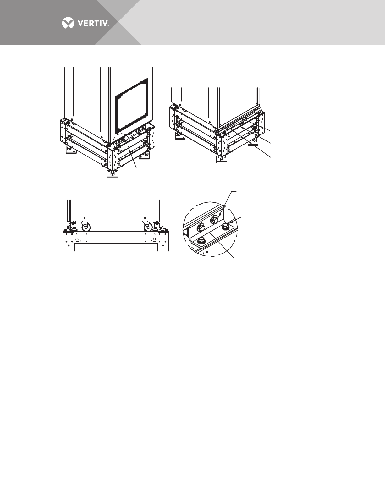
Figure 31 Installation drawing, seismic floor stand 100-250A
r
See Detail A
FIGURE 1
Front Left Isometric View
FIGURE 2
Rear Right Isometric View
2 Places
Cap Screw M10-1.5x30mm
M10 Split Lock Washer
M10 Flat Washer
2 Places
Cap Screw M10-1.5x30mm
M10 Split Lock Washer
M10 Flat Washer
Rear Upper
Liebert STS2 Bracket
Rear Lower
Liebert STS2 Bracket
Upper Rear Bracket Tabs
must slide into Lower Rea
Bracket Slots
FIGURE 3
Right Side View
See Drawings PS215000, PS215001 and PS215003
for details.
DETAIL A
2 Places
Lower Front
Bracket
PS215002
Rev. 1
Vertiv™ | Liebert® STS2™ 100-1000A, 50/60Hz User Manual | Rev. 12 | 11/2017 44
Page 53
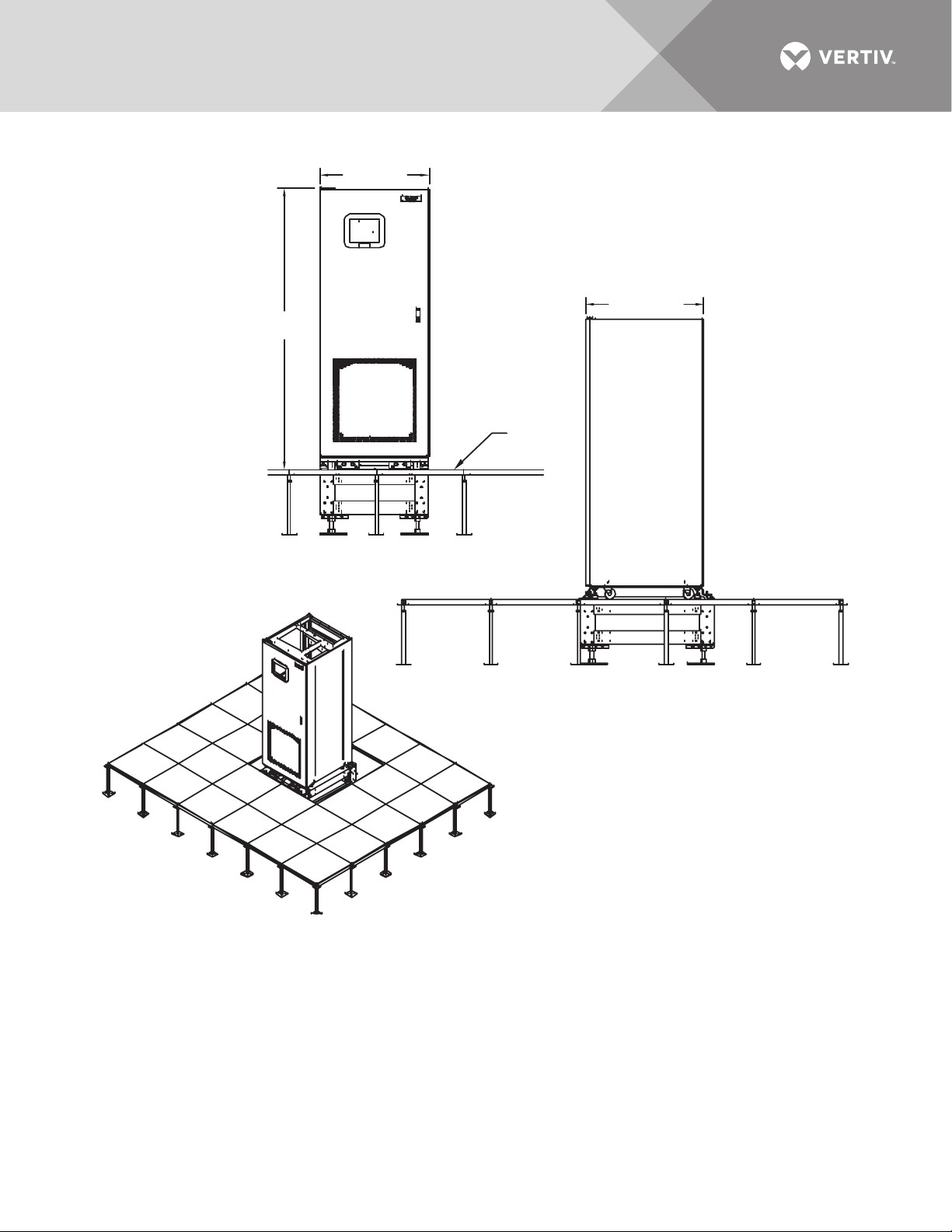
Figure 32 Installation drawing, seismic floor stand 100-250A
See Drawings PS215000, PS215001
and PS215002 for details.
30" (762mm)
77"
(1956mm)
32.1" (815mm)
Raised
Floor
FRONT VIEW
RIGHT SIDE
ISOMETRIC VIEW
PS215003
Rev. 1
Vertiv™ | Liebert® STS2™ 100-1000A, 50/60Hz User Manual | Rev. 12 | 11/2017 45
Page 54
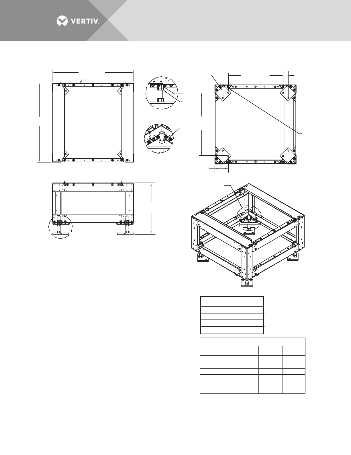
Figure 33 Installation drawing, seismic floor stand 400-600A
38" (965mm)
Front
36.9"
(937mm)
FOOT DETAIL A
FOOT DETAIL B
Align Foot parallel
to Mounting Plate
as shown
Nut
Jam
Nut
(748mm)
Nut
29.44"
Typical
25.59" (650mm)
Typical
2.47"
(63mm)
Typical
B
Mounting
Plate
TOP
See Height
Table
FRONT
A
INSTALLATION NOTES
1. Check all hardware for proper torque before installation.
2. Attach rear lower Liebert STS2 bracket to the floor stand using existing holes
with bent flange facing the front of the floor stand (see Figures 3 and 4 on
drawing PS216001). Use an M12-1.75x40mm cap screw, split lock washer
and flat washer and torque to 53 ft./lb.
3. Loosen the Liebert STS2 adjustable leveling foot nuts (see Detail C, Drawing
PS216001). Install the rear upper Liebert STS2 bracket using existing holes
on the underside of the Liebert STS2 with tabs facing out (Figures 1 and 2,
Drawing PS216001). Install the front upper Liebert STS2 bracket using existing
holes on the underside of the Liebert STS2 with the bent flange facing to the front
(Figures 1 and 2, Drawing PS216001). Use an M12-1.75x40mm cap screw,
split lock washer flat washer and and torque to 53 ft. lb. Retighten the leveling foot nuts.
4. The floor stand can be installed next to a wall if needed; rear access is
not required. Install the floor stand with its feet oriented as shown in
the bottom view of Drawing PS216000. The floor stand must be level and all
feet must be touching the floor. Attach the floor stand feet using 1/2" x 4"
Red Head Trubolts expansion anchors (field-supplied); two per foot.
5. Roll the Liebert STS2 onto the floor stand so that the tabs on the rear upper
Liebert STS2 bracket fit into the slots on the rear lower Liebert STS2 bracket.
The tabs must extend at least 1/2" (12.9mm) through the floor stand bracket
(Figure 2, Drawing PS216002).
6. Install the lower front brackets (Figure 1, Detail A, Drawing PS216002). Attach
the bracket to the Liebert STS2 using M10-1.50x30mm cap screw, split lock washer
and flat washer. Torque to 31 ft./lb. Attach the bracket to the floor stand using
M12-1.75x40mm cap screw, split lock washer and flat washer. Torque to 53 ft./lb.
PS216000
Rev.2
6"
(152mm)
Typical
B
ISOMETRIC VIEW #1
HARDWARE TORQUE
1.0" Nut 320 ft./lb.
M8 - 1.25
M10 - 1.5
M12 - 1.75
Floor Stand Part No. Height
523405G1 18.0"
523406G1 24.0" 25.25" 22.75"
523407G1 30.0" 31.25" 28.75"
523408G1
528737G2
528737G1
BOTTOM
16 ft./lb.
31 ft./lb.
53 ft./lb.
HEIGHT TABLE
36.0" 37.25" 374.75"
14.0"
12.0"
Maximum
Height
19.25"
15.25"
13.25"
Minimum
Height
16.75"
12.75"
10.75"
Vertiv™ | Liebert® STS2™ 100-1000A, 50/60Hz User Manual | Rev. 12 | 11/2017 46
Page 55
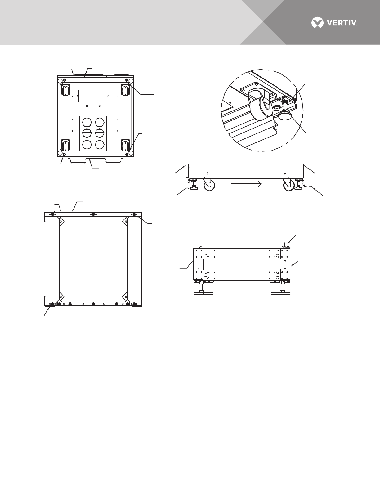
Figure 34 Installation drawing, seismic floor stand 400-600A
Front
Front Upper
Liebert STS2 Bracket
2 Places
Cap Screw M12-1.75x40mm
M12 Split Lock Washer
M12 Flat Washer
See Detail C
Leveling
Foot
Nut
Rear
Side
Rear Upper Liebert STS2 Bracket
FIGURE 1
Bottom of Liebert STS2
with Upper Brackets
Rear
Front
Rear Lower
Liebert STS2 Bracket
FIGURE 4
Top of Floor Stand
with Lower Rear Mounting Bracket
2 Places
Cap Screw M12-1.75x40mm
M12 Split Lock Washer
M12 Flat Washer
DETAIL C
Front
Front Upper
Liebert STS2
Bracket
3 Places
Cap Screw M12-1.75x40mm
M12 Split Lock Washer
M12 Flat Washer
Right Side of Liebert STS2 with Upper Brackets
Front
FIGURE 2
FIGURE 3
Right Side of Floor Stand
with Lower Rear Mounting Bracket
See Drawings PS216000, PS216002 and PS216003
for details.
Leveling
Foot
Rear
Rear Upper
Liebert STS2
Bracket
Rear Lower
Bracket
Rear
PS216001
Rev. 1
Vertiv™ | Liebert® STS2™ 100-1000A, 50/60Hz User Manual | Rev. 12 | 11/2017 47
Page 56
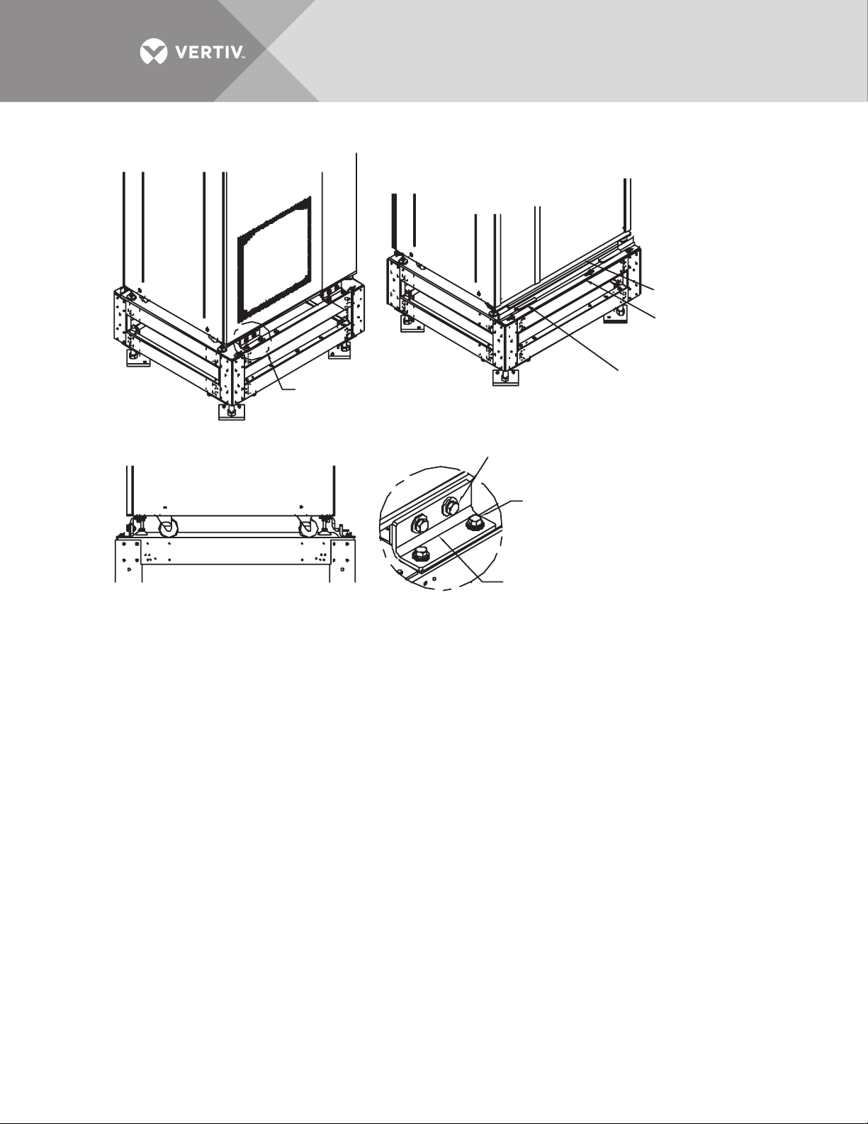
Figure 35 Installation drawing, seismic floor stand 400-600A
PS216002
Rev. 1
Rear Upper
Liebert STS2 Bracket
Upper Rear Bracket Tabs
must slide into Lower Rear
Bracket Slots
Rear Lower
Liebert STS2 Bracket
2 Places
Cap Screw M10-1.5x30mm
M10 Split Lock Washer
M10 Flat Washer
2 Places
Cap Screw M10-1.5x30mm
M10 Split Lock Washer
M10 Flat Washer
Lower Front
Bracket
See Drawings PS216000,
PS216001 and PS216003
for details.
FIGURE 1
Front Left Isometric View
FIGURE 2
Rear Right Isometric View
FIGURE 3
Right Side View
See Detail A
DETAIL A
2 Places
Vertiv™ | Liebert® STS2™ 100-1000A, 50/60Hz User Manual | Rev. 12 | 11/2017 48
Page 57
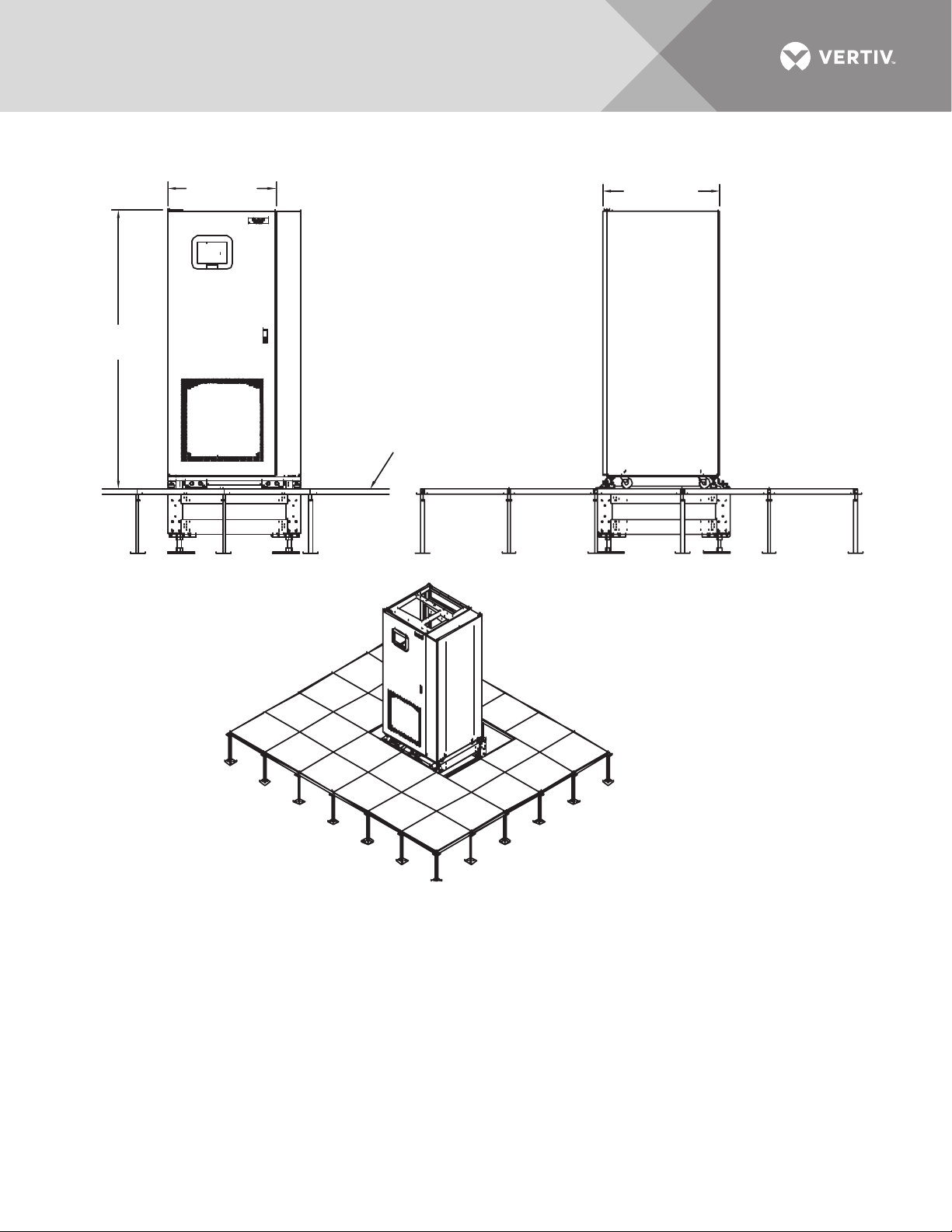
Figure 36 Installation drawing, seismic floor stand 400-600A
77"
(1956mm)
38"
(965.2mm)
FRONT
32.1"
(815mm)
Raised
Floor
RIGHT SIDE
See Drawings PS216000, PS216001
and PS216002 for details.
ISOMETRIC VIEW
PS216003
Rev. 1
Vertiv™ | Liebert® STS2™ 100-1000A, 50/60Hz User Manual | Rev. 12 | 11/2017 49
Page 58
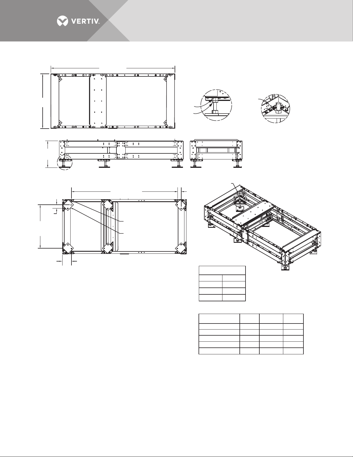
Figure 37 Installation drawing, seismic floor stand 800-1000A
83.9" (2131mm)
36.9"
(937.3mm)
TOP
See Height
Table
A
2.47"
(62.7mm)
Typical
29.44"
(747.8mm)
Typical
6"
(152.4mm)
Typical
INSTALLATION NOTES
1. Check all hardware for proper torque before installation.
2. Install rear lower Liebert STS2 bracket on the floor stand using existing holes with bent
flange facing the front of the floor stand (see Figures 3 and 4 on Drawing PS217001).
Use an M12-1.75x40mm cap screw, split lock washer and flat washer. Torque to 53 ft./lb.
3. Loosen the Liebert STS2 adjustable leveling foot nuts (see Detail C, Drawing
PS217001). Install the rear upper Liebert STS2 bracket using existing holes
on the underside of the Liebert STS2 with tabs facing out (Figures 1 and 2,
Drawing PS217001). Install the front upper Liebert STS2 bracket using existing
holes on the underside of the Liebert STS2 with the bent flange facing to the front
(Figures 1 and 2, Drawing PS217001). Use an M12-1.75x40mm cap screw,
split lock washer and flat washer. Torque to 53 ft./lb. Retighten the leveling foot nuts.
4. The floor stand can be installed next to a wall if needed; rear access is
not required. Install the floor stand with its feet oriented as shown in
the bottom view of Drawing PS217000. To adjust vertical height of floor stand feet,
loosen adjust and tighten the nuts and jam nut shown in (foot Details A and B, on
DWG PS217000).The floor stand must be level and all feet must be touching the floor.
Attach the floor stand feet using 1/2" x 4" Red Head Trubolts expansion anchors
(field-supplied); two per foot.
5. Roll the Liebert STS2 onto the floor stand so that the tabs on the rear upper
Liebert STS2 bracket fit into the slots on the rear lower Liebert STS2 bracket.
The tabs must extend at least 1/2" (12.9mm) through the floor stand bracket
(Figure 2, Drawing PS217002).
6. Install the lower front brackets (Figure 1, Detail A, Drawing PS215002). Attach
the bracket to the Liebert STS2 using M10-1.50x30mm cap screw, split lock washer
and flat washer. Torque to 31 ft./lb. Attach the bracket to the floor stand using
M12-1.75x40mm cap screw, split lock washer and flat washer. Torque to 53 ft./lb.
FRONT
71.55" (1817.4mm)
Mounting
Plate
Align the Foot
To the Mounting
Plate as Shown
BOTTOM
Nut
Jam Nut
FOOT DETAIL A
RIGHT SIDE VIEW
2.47"
(62.7mm)
Typical
Hardware Torque
1.0" Nut
M8 - 1.25
M10 - 1.5
M12 - 1.75
Floor Stand Height
Floor Stand Part No.
523409G1 18.0"
523410G1 24.0"
523411G1
523412G1
542416G1
B
ISOMETRIC
VIEW
320 ft./lb.
16 ft./lb.
31 ft./lb.
53 ft./lb.
PS217000
Rev. 3
Nut
FOOT DETAIL B
Height
30.0"
36.0"
14.0"
Maximum
Minimum
Height
19.25" 16.75"
25.25"
22.75"
31.25" 28.75"
37.25" 34.75"
15.25"
12.75"
Height
Vertiv™ | Liebert® STS2™ 100-1000A, 50/60Hz User Manual | Rev. 12 | 11/2017 50
Page 59
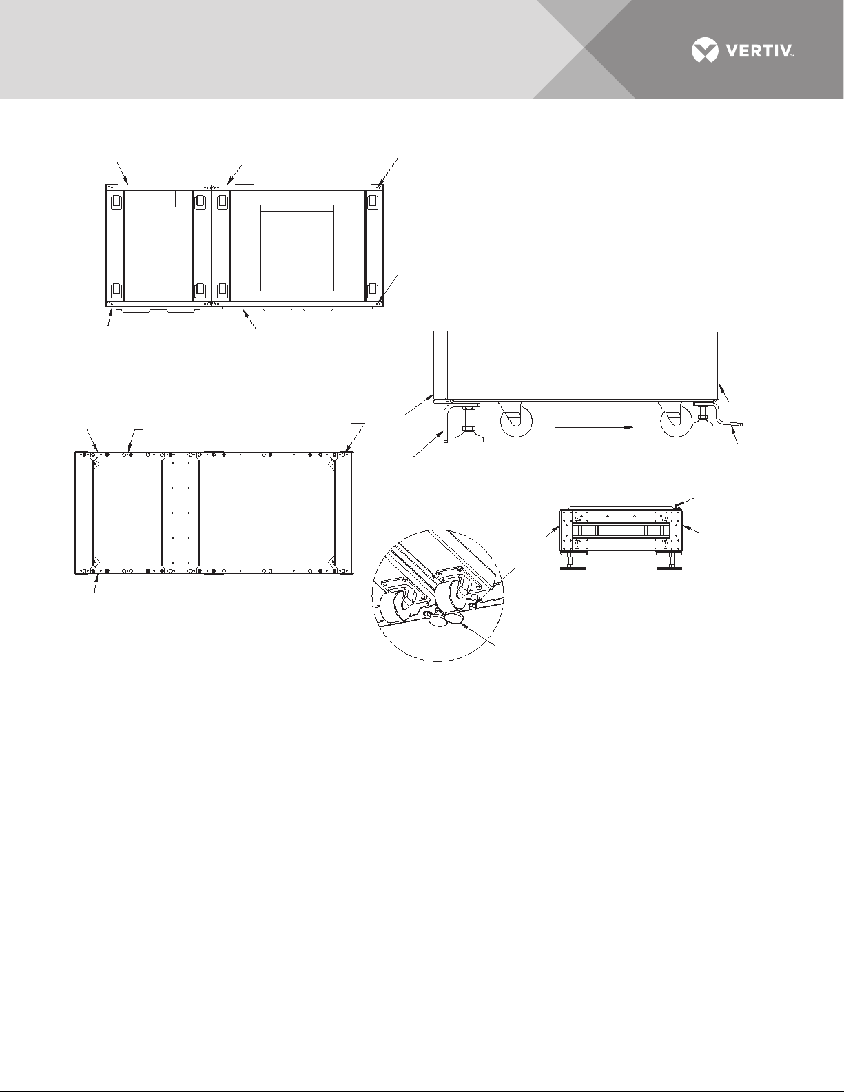
Figure 38 Installation drawing, seismic floor stand 800-1000A
Front
Front
Rear
Rear
Rear
Front
Front Upper
Liebert STS2
Bracket
DETAIL C
Front
Front Upper
Liebert STS2 Bracket
Rear Lower
Liebert STS2 Bracket
Rear Upper
Liebert STS2 Bracket
FIGURE 1
Bottom of Liebert STS2
with Upper Brackets
FIGURE 3
Top of Floor Stand
with Lower Rear Mounting Bracket
FIGURE 2
Right Side of Liebert STS2
with Upper Brackets
FIGURE 4
Right Side of Floor Stand
with Lower Rear Mounting Bracket
PS217001
Rev. 2
Rear
Side
2 Places
Cap Screw M12-1.75x40mm
M12 Split Lock Washer
M12 Flat Washer
See Detail C
2 Places
Cap Screw M12-1.75x40mm
M12 Split Lock Washer
M12 Flat Washer
3 Places
Cap Screw M12-1.75x40mm
M12 Split Lock Washer
M12 Flat Washer
Rear Upper
Liebert STS2
Bracket
Leveling
Foot
Nut
Leveling
Foot
Rear Lower
Bracket
See Drawings PS217000, PS217002
and PS217003 for details.
Vertiv™ | Liebert® STS2™ 100-1000A, 50/60Hz User Manual | Rev. 12 | 11/2017 51
Page 60
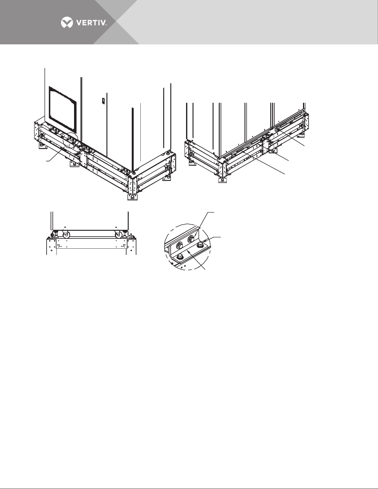
Figure 39 Installation drawing, seismic floor stand 800-1000A
Right Rear Upper
Liebert STS2 Bracket
Upper Rear Bracket Tabs
must slide into Lower Rear
Bracket Slots
Right Rear Lower
Liebert STS2 Bracket
2 Places
Cap Screw M10-1.5x30mm
M10 Split Lock Washer
M10 Flat Washer
2 Places
Cap Screw M10-1.5x30mm
M10 Split Lock Washer
M10 Flat Washer
Lower Front
Bracket
See Drawings PS217000, PS217001
and PS217003 for details.
FIGURE 1
Front Right Isometric View
FIGURE 2
Rear Right Isometric View
FIGURE 3
Right Side
See
Detail A
DETAIL A
4 Places
PS217002
Rev. 1
Vertiv™ | Liebert® STS2™ 100-1000A, 50/60Hz User Manual | Rev. 12 | 11/2017 52
Page 61
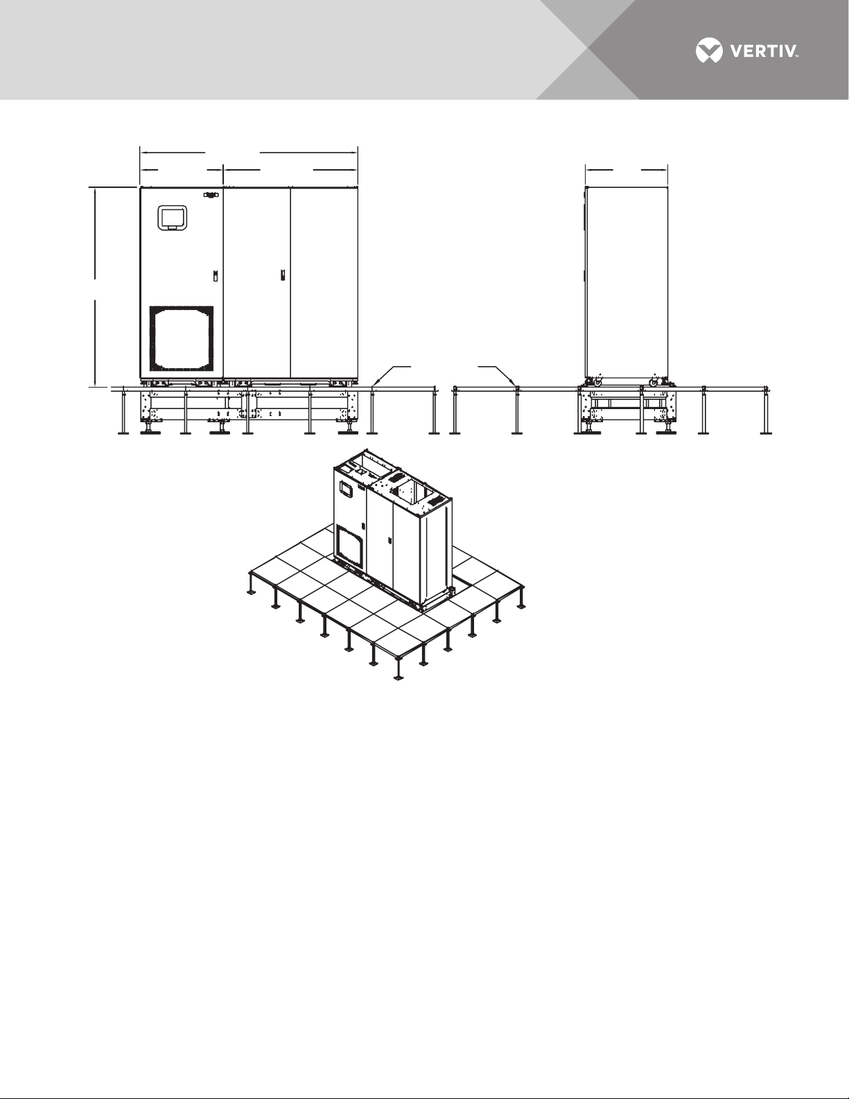
Figure 40 Installation drawing, seismic floor stand 800-1000A
84" (2134mm)
77"
(1956mm)
32.1"
(815mm)
Raised Floor
FRONT
RIGHT SIDE
ISOMETRIC VIEW
32" (813mm) 52" (1321mm)
PS217003
Rev. 1
See Drawings PS217000, PS217001 and PS217002 for details.
Vertiv™ | Liebert® STS2™ 100-1000A, 50/60Hz User Manual | Rev. 12 | 11/2017 53
Page 62

8.0 INTRODUCTION TO LIEBERT STS2 OPERATIONS
8.1 System Description
A Liebert STS2 provides an automatic, seamless transfer between input power sources to an output load. The
Liebert STS2 monitors the input sources, to ensure each source is operating within set parameters, as well as
ensure that each source is within acceptable tolerances for a transfer between sources to be completed.
The Liebert STS2 contains two static transfer switches in one enclosure to allow the unit to transfer its load
between the two input sources without an interruption of power to the load longer than 1/4 cycle when utilizing
the standard transfer algorithm. When utilizing the Optimized transfer option the interruption does not exceed
the ITIC/CBEMA standard.
If a problem is detected with a primary (Preferred) input source and defined trigger points are reached, the
Liebert STS2 automatically switches the input to the other (Alternate) input source. The Liebert STS2 continues
to monitor both sources and can automatically transfer the load back to the preferred source, if so configured,
when that source returns to acceptable operating parameters.
The system control logic automatically monitors the input sources and power output to ensure that they are
operating within acceptable tolerances. The system logic manages the transfer between sources.
The Liebert STS2 front panel contains either a Color Graphical Display on an LCD touchscreen or an LED display.
The Color Graphical Display provides a menu-driven operator interface, and a display of system information,
status information, a one-line diagram (Mimic) of the Liebert STS2, active alarms, and alarm history information.
The menu selections provide control of the preferred source and manual transfer initiation. Buttons provide for
audible alarm silence and reset.
Through the touchscreen, specific voltage, current and environmental parameters can be configured to trigger
events that can sound an alarm, write to a history log and either transfer sources or inhibit a transfer.
In units not equipped with the touchscreen, LED’s provide the user with the ability to monitor the Liebert STS2
and quickly assess problems.
Preferred input source selection, alarm reset and alarm silencing are done through buttons on the touchscreen,
or push buttons with the LED display.
Communication options can be installed in the Color Graphical Display (LCD) unit only. These options provide
external communication with the Liebert STS2 through a network card, a programmable relay board, a contact
isolator, or an RS-422 port to Liebert SiteScan.
8.1.1 Redundancy
Redundancy within the Liebert STS2 prevents one component from being a single point of failure, should a
problem occur. Redundant circuits and components are used to eliminate single points of failure.
Since the Liebert STS2 has two input sources, no single component failure can cause a loss of power to the load.
Redundant power supplies are provided which feed a DC dual-bus used throughout the unit to prevent any
single-point power supply failure modes.
Three separate redundant control logic modules are built into the system. Each contains the logic necessary to
run the Liebert STS2, and control all transfers.
Redundant fans are provided if a primary fan fails. The redundant fans turn On to prevent overheating inside of
the unit.
Should the front panel interface fail, either touchscreen or LED’s, the control logic continues to operate and the
unit would transfer should a problem be detected on the preferred source. Information on the monitoring
parameters would be available through the remote communication options, if available, or the DB9 (RS-232)
connector located next to the LCD display behind the front door. See Figure 26 on page 39 for details.
Vertiv™ | Liebert® STS2™ 100-1000A, 50/60Hz User Manual | Rev. 12 | 11/2017 54
Page 63

8.1.2 Reliability and Agency Requirements
The Liebert STS2 is designed for high reliability and high availability with a critical bus Mean Time Between
Failure (MTBF) exceeding 1,000,000 hours.
The Liebert STS2, Control/Power Module and all its options are designed, tested and certified, where applicable,
to meet agency requirements as follows:
• UL 1008: Transfer Switch Equipment, for UL and ULc listing
•NEC
• FCC Part 15 EMI emission limits for Class A computing devices.
The Liebert STS2 uses conservatively rated components, minimizing the need to go to maintenance bypass. All
maintenance and repair work can be done through the front panel of the unit. This access makes repairs and
maintenance easier.
Gating and control logic are partitioned so that failure of one source’s gating or sensing logic does not prevent
the switch from transferring to the other source.
All control and logic components are mounted separate from the power components. The Liebert STS2 is
designed to minimize the exposure of hazardous voltages to allow safe servicing of the unit while the load is
energized.
All electrical components requiring normal maintenance are replaceable without de-energizing the load, as long
as one source is available. Solid-state switching devices are packaged to allow safe repair of those devices
without having to de-energize the load. All non-automatic switches or circuit breakers are the plug-in or drawout type to allow replacement without de-energizing the load. All solid-state power switching devices are rated
to prevent hazardous device failure in power systems with available fault currents up to the defined limits, as
listed in 15.1.5 - Electrical Requirements.
8.1.3 Factory Backup and Service Assistance
Because improper installation can cause a system to fail, a Vertiv Services service technician should thoroughly
inspect the unit to ensure it is properly installed and its operating parameters are properly configured.
Once the Liebert STS2 is properly installed, you, as the on-site operator, can easily monitor the unit’s operation
utilizing the touchscreen or LED’s.
If you need assistance, or have questions, contact Vertiv Services at 800-543-2378.
8.2 Modes of Operation
8.2.1 Normal (Preferred Source)
Under normal operating conditions, the Liebert STS2 routes power from the preferred input source to the output
load. The unit monitors the voltage current and phase of each source to ensure that both are operating within
set tolerances, and that the alternate source is available, should a transfer be required
8.2.2 Transfer
Should the preferred source fail or be outside acceptable voltage limits, the Liebert STS2 transfers the input to
the alternate source until the problem is rectified in the preferred source. The unit can be set to automatically
transfer the input back to the preferred source, or only allow the transfer to be done manually.
8.2.3 Transfer Inhibit
For a transfer to be completed between input sources, the sources must meet certain parameters, or the transfer
cannot take place. Uninterrupted transfer between sources is inhibited due to input source failure, sources out of
sync, switch failure, or the unit is in bypass mode.
Vertiv™ | Liebert® STS2™ 100-1000A, 50/60Hz User Manual | Rev. 12 | 11/2017 55
Page 64
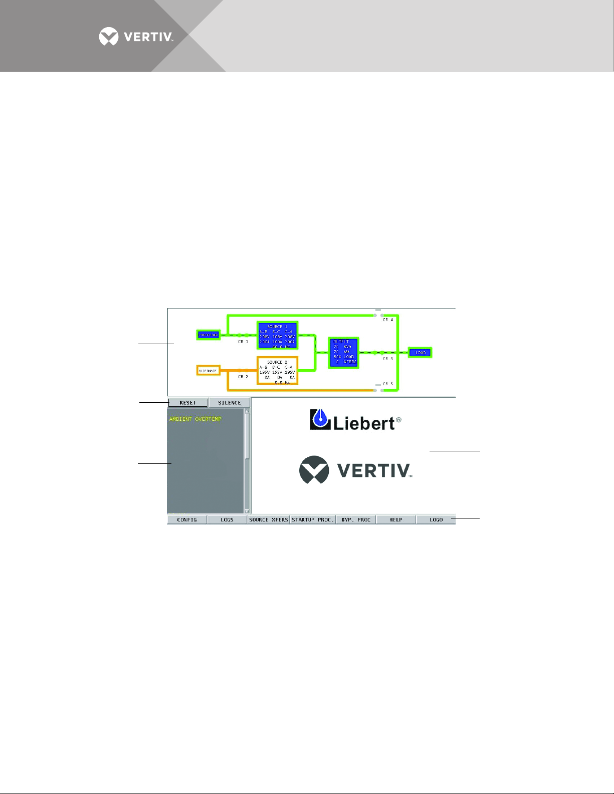
8.2.4 Bypass
Mimic
Event Display
Event controls
Display Panel
and
Help Screen
Menu Options
The static transfer switch can be manually bypassed to allow the power from a source to directly flow to the
output load. This bypass allows the unit’s electronics to be serviced without dangerous voltages being present.
The Liebert STS2 includes key-interlocked maintenance bypass breakers that allow either input source’s
electronics to be bypassed for maintenance without interruption of power to the load. The maintenance bypass
allows all electronics to be isolated from the input, output, and bypass connections. Bypass instructions are
available from the touchscreen and are discussed later in this manual.
8.3 Operator Controls
The Liebert STS2 is equipped with an interface to configure and monitor the unit either locally or remotely. The
Color Graphical Display is a touchscreen LCD that provides a color diagram (Mimic) that displays the current
status of the unit. System parameters are displayed and help is available to define events. See Figure 41. The
touchscreen menus allow the operator to initiate source transfers, view event and history logs, and view bypass
and other operational instructions.
Figure 41 Liebert STS2 touchscreen display
Touchscreen control buttons allow you to reset alarms, silence the audible alarm, review configurations, event
and history logs, preferred source, startup and bypass procedures, and the help menu. Qualified personnel, with a
password, can use these menus to configure parameters, select a preferred source and do manual source
transfers.
LED display units do not have the color LCD touchscreen. Instead of the touchscreen, these units are monitored
by a series of LED’s and controlled by a series of push buttons.
Both units can be accessed from a terminal, or a PC running terminal emulation software, that is attached to the
unit. Through the RS-232 access, you can monitor and configure the unit, plus remotely select a preferred
source. See 12.1 - Using the RS-232 Port on page 73 for instructions on using the RS-232 interface.
Vertiv™ | Liebert® STS2™ 100-1000A, 50/60Hz User Manual | Rev. 12 | 11/2017 56
Page 65

9.0 THEORY OF OPERATION
9.1 General Description
The Liebert STS2 contains all the equipment necessary to prevent an interruption in power flow to the AC load,
should your primary source fail.
9.1.1 Liebert STS2 Static Transfer Switch
The Liebert STS2 is a 3-pole, double-throw, solid state automatic transfer switch that is fed from two sources.
The Preferred source is the input source that normally carries the load when both sources are available. The
preferred source is selectable by the user from the LCD panel or an optional Remote Source Selection. The
unselected source is referred to as the Alternate source and carries the load if the preferred source should fail or
if a manual transfer is initiated.
The unit uses Silicon Controlled Rectifiers (SCRs) connected in parallel, opposing pairs to function as an AC
switch configuration. Three pairs of SCRs connect the AC load to the selected preferred input source as long as
the preferred source is available. A second set of SCRs stands ready to transfer the AC load to the alternate input
source should the preferred source fail. The switching action is a very fast, break-before-make without an
interruption of power to the load longer than 1/4 cycle when utilizing the standard transfer algorithm. When
utilizing the Optimized transfer option the interruption does not exceed the ITIC/CBEMA standard.
During static switch transfers and retransfers, the conduction state of the SCRs is carefully monitored and
controlled to prevent a current path from one source to the other. This technique prevents a faulted source from
feeding into the other good source.
9.1.2 Source Transfer
The Liebert STS2 allows manually initiated transfers between the two sources. On units without the Optimized
Transfer option the alternate source must be within acceptable voltage limits and phase tolerances with the
preferred source. You begin a manual transfer by selecting the inactive source as the preferred source. On a
manual transfer, the Liebert STS2 transfers between the two sources with less than one (1) millisecond
interruption of power to the load. The transfer can only be completed when both sources are available and
synchronized within the user-adjustable phase synchronization window. For sources where the two frequencies
are not exactly in phase, manually initiated transfers are delayed by the Liebert STS2 until the two sources are
within the defined phase synchronization window.
The Liebert STS2 with Optimized Transfer option allows manually initiated transfer at any phase difference and
does not require synchronization, as long as the alternate source is within acceptable voltage limits with the
preferred source. Transfer is not delayed if the two frequencies are not in phase. When Optimized Transfer is
enabled, the out-of-sync alarm is NOT active.
Source selection can also be done remotely using the Remote Source Selection option, if installed.
9.1.3 Automatic Transfer/Retransfer
If the preferred source is out of voltage and/or frequency limits, the load is automatically transferred to the
alternate source. The default transfer voltage limits comply with the limits of the IEEE Std. 446-1995 computer
voltage tolerance envelope.
If the unit is so configured, the load is retransferred automatically to the preferred source after the preferred
source returns to within the acceptable voltage and frequency limits for at least the defined retransfer time delay,
and is in phase with the alternate source. You can enable and disable automatic retransfer to the preferred
source through a user configuration setting.
Vertiv™ | Liebert® STS2™ 100-1000A, 50/60Hz User Manual | Rev. 12 | 11/2017 57
Page 66

Automatic Retransfer Inhibited
If the system makes five transfers from the preferred source to the alternate source in a five minute period,
automatic retransfers back to the preferred source is disabled.
To clear this alarm condition, you must assign the alternate source as the preferred source.
Also, the UV detection thresholds may need adjustment. See Source Set Points on page 87 for instructions on
setting the UV detection.
This alarm also is cleared if the unit transfers to the preferred source due to an alternate source AC volt failure
(i.e., an emergency transfer.)
9.1.4 Emergency Transfer
To ensure that power remains connected to the load, the Liebert STS2 automatically performs an emergency
transfer from one input source to the other when an outage occurs on the existing source. The automatic
transfer takes place if the other source’s voltage is within acceptable limits, and regardless of the phase
difference between the two sources.
Emergency transfers occur without an interruption of power to the load longer than 1/4 cycle when utilizing the
standard transfer algorithm.When utilizing the Optimized transfer option the interruption does not exceed the
ITIC/CBEMA standard.
Emergency transfers from the alternate source to the preferred source are not affected by the Auto Retransfer
Enabled/Disabled or Retransfer Delay user settings.
9.1.5 Load Current Transfer Inhibit
The Liebert STS2 senses the load current. If the load current exceeds the preset level deemed to represent a
load inrush or fault condition, the unit’s logic disables manual and automatic transfers, even if the selected
source’s input voltage is outside the acceptable limits. This event triggers an I-Peak alarm. If so configured, the
Load Current Transfer Inhibit is automatically reset 100 milliseconds after the current and voltage return to
within normal parameters. This reset provides continued protection against a source failure. The Load Current
Transfer Inhibit also can be programmed to require a manual reset. See Step 14. on page 89 under the Source
Set Points heading for details. Only under open SCR condition would the Liebert STS2 automatically transfer
with an IPeak condition.
9.1.6 SCR Failure
The Liebert STS2 continuously monitors the status of the SCR switching devices for proper operation. In the
event of a shorted SCR on the input source powering the load, the Liebert STS2 automatically triggers an alarm
and trips open the other source isolation breaker. In the event of a shorted SCR on the other input source, the
Liebert STS2 automatically triggers an alarm and trips open the other source isolation breaker.
In the event of an open SCR, the switch automatically triggers an alarm and transfers the load to the other
source. All open and shorted SCR alarm conditions are latched and require the system to be repaired and reset
to restore normal operation.
9.1.7 On/Off Sequence
The Liebert STS2 contains no master On/Off push button control. When connected to the input sources, the
unit’s logic power comes On automatically. The touchscreen display (if so equipped) is active as long as at least
one input source is energized and the Control Power Disconnect (located inside the static switch) is On.
Vertiv™ | Liebert® STS2™ 100-1000A, 50/60Hz User Manual | Rev. 12 | 11/2017 58
Page 67

9.2 Detailed Component Description
9.2.1 Controls
Operator Interface
The Liebert STS2 Color Graphical Display unit contains a touchscreen color LCD to provide the operator
interface to control and configure the operation of the unit and quickly diagnose problems. A password and an
optional keylock, if installed, are provided for security.
The LED Display unit includes push buttons for source transfer, alarm reset and audible alarm silence.
Hardware
• The Liebert STS2 operator interface in the Color Graphical Display unit is designed to provide all of the information required
to configure and monitor the unit’s operation.
• The control logic performs automatic operations with minimal operator interface.
• Each Liebert STS2 unit is equipped with either a color LCD touchscreen or a panel of LED’s and push buttons.
• The Liebert STS2 can have optional communication ports installed. See 6.0 - Options and 12.0 - Communication
Interfaces on page 73 for more information on communication options.
• On LED Display units, the RS-232 interface is used for configuration and status and event log monitoring. The RS-232
interface can also be used with the Color Graphical Display units, if necessary.
Firmware
The operator interface enables you to monitor the Liebert STS2, to configure set points for transfers, monitor
system parameters and access event and history logs. The firmware is accessible through the LCD touchscreen
(if installed) or the RS-232 interface. The firmware includes:
• View and set the preferred source.
• View and configure setpoints.
• View alarms, faults and status.
Additionally, the Color Graphical Display unit provides:
• The mimic graphical representation of the systems operation.
• Menu driven monitoring and configuration.
• Step-by-step instructions to assist you in the startup, shutdown and bypass operations.
• Help on event messages.
• Touchscreen alarm reset and silence buttons.
Events in the system, both faults and alarms, are detected and displayed on the LCD. See 11.0 - Alarm and
Faults on page 68 for more information on events.
• A set of event masks can be configured through the LCD to trigger a system response to an event. See 11.1 - Event Mask.
• Report event conditions from other components of the system.
• Monitor and report changes in event condition states. If the event condition’s state changes from inactive to active, a new
event is detected. If the transition is from active to inactive, the event condition has cleared.
• Process new faults and alarms, and clear inactive alarms.
• Provide the alarm reset and silence options.
9.2.2 Circuit Breakers
Three circuit breakers provide total isolation of the solid-state switching devices with an input breaker for each
source and a load isolation breaker. Two breakers provide for maintenance bypassing of the solid-state switching
devices to either input source.
All switches in the Liebert STS2 are plug-in types, which allows any switch to be replaced without de-energizing
the output bus. The breakers have an interlock in the plug-in base, which prevents the switch from being
withdrawn in the CLOSED position. The switch trips OPEN before it disconnects from the plug-in base.
See 15.2.5 - Circuit Breakers for specifications and more information pertaining to the circuit breakers. See
Figure 13 to Figure 18 for circuit breaker locations. See submittal PS214002 for the circuit breaker schedule .
Vertiv™ | Liebert® STS2™ 100-1000A, 50/60Hz User Manual | Rev. 12 | 11/2017 59
Page 68

9.2.3 SCR’s
The unit uses brick-type SCRs rated to carry the full load. Because the unit is a fuseless design with
non-automatic circuit breakers, overcurrent protection is provided by upstream circuit breakers.
9.2.4 Logic Modules
The logic contains three separate redundant logic modules. Each module contains the logic necessary to run the
Liebert STS2 and control transfers and shunt trips under all circumstances, without any outside assistance, once
set up and started properly.
9.2.5 Audible Alarm
An audible alarm is installed on the control board. This alarm is triggered by an alarm condition detected on the
unit. The alarm can be turned Off from the touchscreen (Color Graphical Display units) or by a push button (LED
Display units). Turning Off the audible alarm does not clear or reset the condition that triggered the alarm.
9.2.6 RS-232 Port
An RS-232 serial port is provided to allow an external terminal to be connected as another user interface. See
12.1 - Using the RS-232 Port on page 73 for more information on using the RS-232 port.
Vertiv™ | Liebert® STS2™ 100-1000A, 50/60Hz User Manual | Rev. 12 | 11/2017 60
Page 69

10.0 OPERATING INSTRUCTIONS FOR THE TOUCHSCREEN INTERFACE
CAUTION
Before the unit is placed into service for the first time, after equipment relocation, or after the equipment
has been de-energized for an extended period of time, a thorough equipment inspection and supervised
startup by qualified personnel are strongly recommended. Contact your local Vertiv representative or
Vertiv Services at 800-543-2378 to arrange for equipment inspection and startup.
After the initial equipment startup, the following operating guidelines can be used for standard equipment
operation. These guidelines should be reviewed for any special equipment modifications, special site conditions,
or company policies that may require changes to the standard equipment operation.
All programmable functions are preset at the factory to enable the unit to be brought up without the need to
enter all selectable parameters.
This section refers to the LCD touchscreen display. This display is discussed in more detail later in the manual.
See 13.0 - Liebert STS2 Touchscreen Display.
NOTE
If the front panel of your Liebert STS2 has LED’s and push buttons instead of the touchscreen interface, refer to
14.0 - Operating the Liebert STS2 LED Display for operating instructions.
See Figures 13 - 18 for circuit breaker locations.
Vertiv™ | Liebert® STS2™ 100-1000A, 50/60Hz User Manual | Rev. 12 | 11/2017 61
Page 70

10.1 Normal System Startup
NOTE
If your Liebert STS2 is connected to a PDU with a Wye configuration, enable the Wye Output Transformer before
starting the system. This setting can be made from the touchscreen. Refer to Wye Output Transformer on
page 95 for instructions.
1. Ensure that all Liebert STS2 breakers—CB1, CB2, CB3, CB3A (if supplied), CB4, and CB5—are in the OFF position.
a. Ensure that the key interlocks for CB1 and CB2 have their bolts retracted.
b. Ensure that the key interlocks for CB4 and CB5 have their bolts extended, thus preventing CB4 or CB5 from being
turned ON.
2. Source/input power should be applied to both Liebert STS2 inputs.
The touchscreen control panel should become active and operate properly when at least one of the inputs is energized is
closed.
3. Verify that nominal input voltages are applied to both inputs (Source 1 and Source 2).
The input voltages, selected preferred source, breaker and switch status, and alarms are indicated on the Mimic screen.
4. Close CB1.
5. Verify that Source 1 voltages are nominal and CB1 breaker status is correctly indicated on the Monitor/Mimic screen.
6. Close CB2.
7. Verify that Source 2 voltages are nominal and CB2 breaker status is correctly indicated on the Mimic screen.
8. Verify that boxes for the preferred source and corresponding static transfer switch are highlighted on the Mimic screen,
indicating which side of the Liebert STS2 is on.
9. Close Output Breaker CB3 (and CB3A in redundant output configurations).
10. Verify CB3, the Output box, and the Load box are highlighted, indicating that CB3 is closed and the Output and Load are
energized.
NOTE
For redundant output switch units, CB3 descriptions apply to CB3 and CB3A.
11. Press the RESET button on the touchscreen to reset any previous alarms.
12. Verify in the Event Display and the Mimic that there are no active alarms.
If any active alarms are displayed, refer to 11.0 - Alarm and Faults for a description of the alarms and possible causes. All
active alarm conditions should be corrected before proceeding.
13. Turn On the load equipment following the load equipment manufacturer’s recommendations.
10.2 Manual Transfer / Preferred Source Selection
The Source Transfer option (Source Xfers) in the touchscreen menu allows you to select a preferred source.
Transfers are only permitted when the voltage and current are within their proper operating range and the
sources are synchronized on units without Optimized Transfer. Units with the Optimized Transfer option do not
require the sources to be synchronized to make a manual transfer. The Source Transfer screen indicates the
synchronization between the two sources, while the voltage and frequency are displayed on the Mimic. See
Figure 42. Transfer is inhibited if the deviation exceeds the parameter set in the Source Set Points. See User
Settings on page 86
NOTE
If one source will be de-energized for an extended period (hours or days), set the unit to bypass mode for the
remaining source. Without using bypass, if a failure occurs in the switch components for remaining source, the
Liebert STS2 does not have a second source to switch to and the load would not receive power. See
Maintenance Bypass on page 64 for bypass instructions.
If your system contains the LED front panel instead of the LCD touchscreen, refer to 14.2.2 - Manual Transfer /
Preferred Source Selection for instructions on this procedure.
Vertiv™ | Liebert® STS2™ 100-1000A, 50/60Hz User Manual | Rev. 12 | 11/2017 62
Page 71
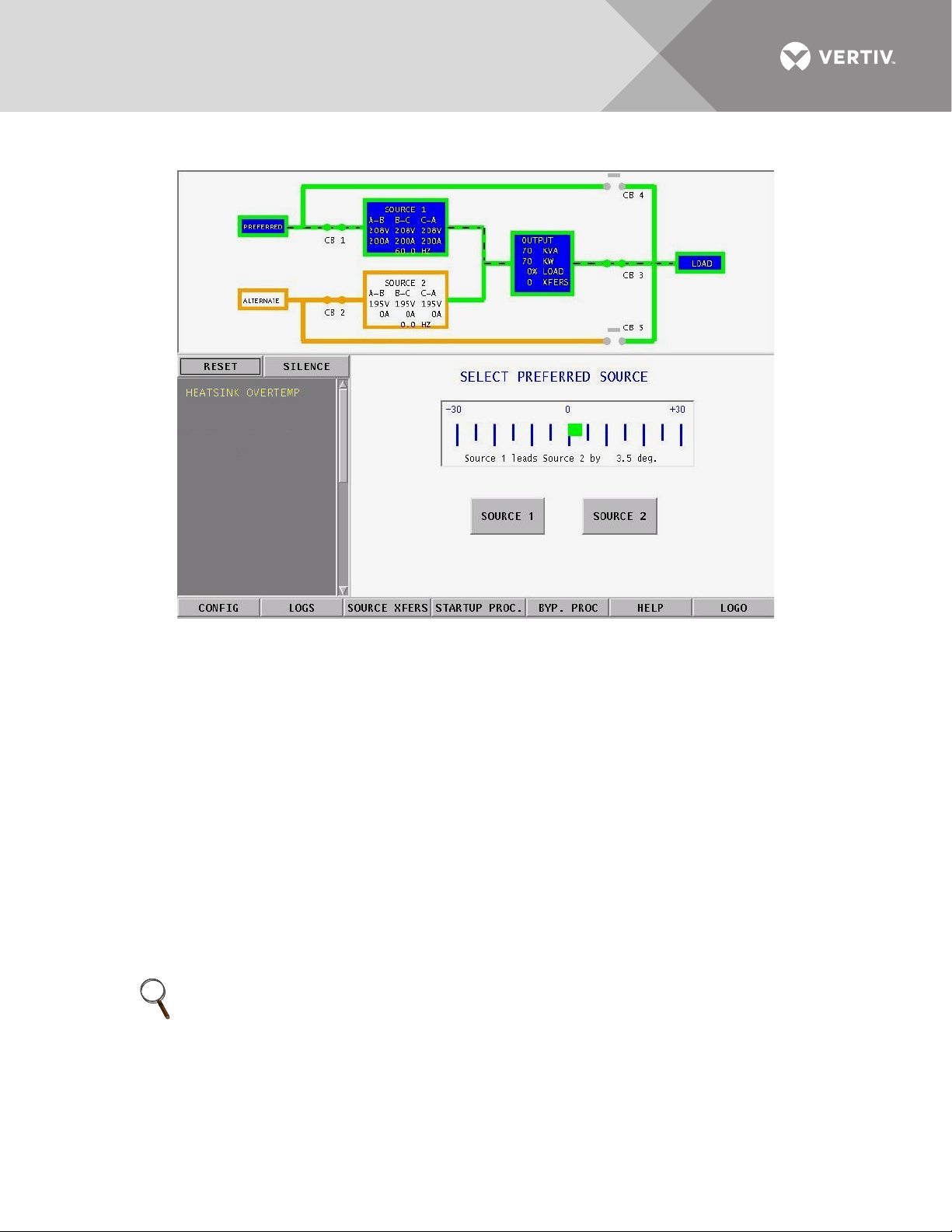
Figure 42 Source transfer screen
To manually select the preferred source:
1. Verify that the input breakers CB1 and CB2 are closed.
2. Select SOURCE XFERS from the menu bar.
The Select Preferred Source screen is displayed in the Event Display.
3. Check the Mimic to verify that Source 1 and Source 2 input voltages are correct.
4. Select SOURCE 1 or SOURCE 2 as your preferred source.
When conditions are correct, the switch transfers the load to the alternate source by selecting the alternate source as the
preferred source.
This source is now monitored as the preferred source throughout the various configurations set up through the
touchscreen.
5. Verify that the correct source is designated as the preferred source and that the input source changes to the desired
source.
The Mimic is updated to indicate the new preferred source. The source is now highlighted with blue and that
source is labeled as the preferred source.
If the Transfer Inhibit message is displayed, check for alarm messages on the Active Status window. Correct
alarm conditions before attempting a source transfer.
NOTE
The preferred source may also be changed via the optional Remote Source Selection option, thereby initiating a
transfer remotely.
Vertiv™ | Liebert® STS2™ 100-1000A, 50/60Hz User Manual | Rev. 12 | 11/2017 63
Page 72

10.3 Enabling Remote Source Selection
If your system is equipped with the optional Remote Source Selection option, it must be enabled.
If you your system includes the Color Graphical Display:
1. Select CONFIG from the menu bar.
2. Select SYSTEM SETTINGS from the Configuration menu.
3. Select SYSTEM OPTIONS from the System Settings menu.
4. Select YES for the REMOTE SOURCE SELECT choice.
If your system contains the LED display or you are configuring the system from the RS-232 port, see 12.1 - Using
the RS-232 Port on page 73 for instructions on using the that interface.
10.4 Maintenance Bypass
The Liebert STS2 is equipped with two key-interlocked, bypass breakers, CB4 and CB5, to allow manual bypass
of the switch electronics for either input source in the event of switch failure or for maintenance of the switch.
Refer to the static transfer switch one-line diagram (Figure 2). While operating on maintenance bypass, all
voltages are removed from the Liebert STS2 electronics to facilitate safe repair, without de-energizing the load
using a make-before-break switching sequence.
However, the unit can be bypassed using a make-before-break switching sequence only to the same source to
which that the switch is connected, as indicated by the highlighted static transfer switch box on the Mimic
screen.
In the event of source or switch failure, the unit should be bypassed only to the current input source. For
convenience, instructions for the bypass procedure can be displayed on the touchscreen by selecting the BYP.
PROC option from the menu bar.
The Mimic is used to verify the status of the unit during the bypass procedures. In the unlikely event that the
Color Graphical Display is not available, open the front door and look through the slots in the control door. If you
can see green LED’s on the gate driver board through that slot, then the unit is connected to the source
referenced on the label below that slot. See Figure 43.
Vertiv™ | Liebert® STS2™ 100-1000A, 50/60Hz User Manual | Rev. 12 | 11/2017 64
Page 73
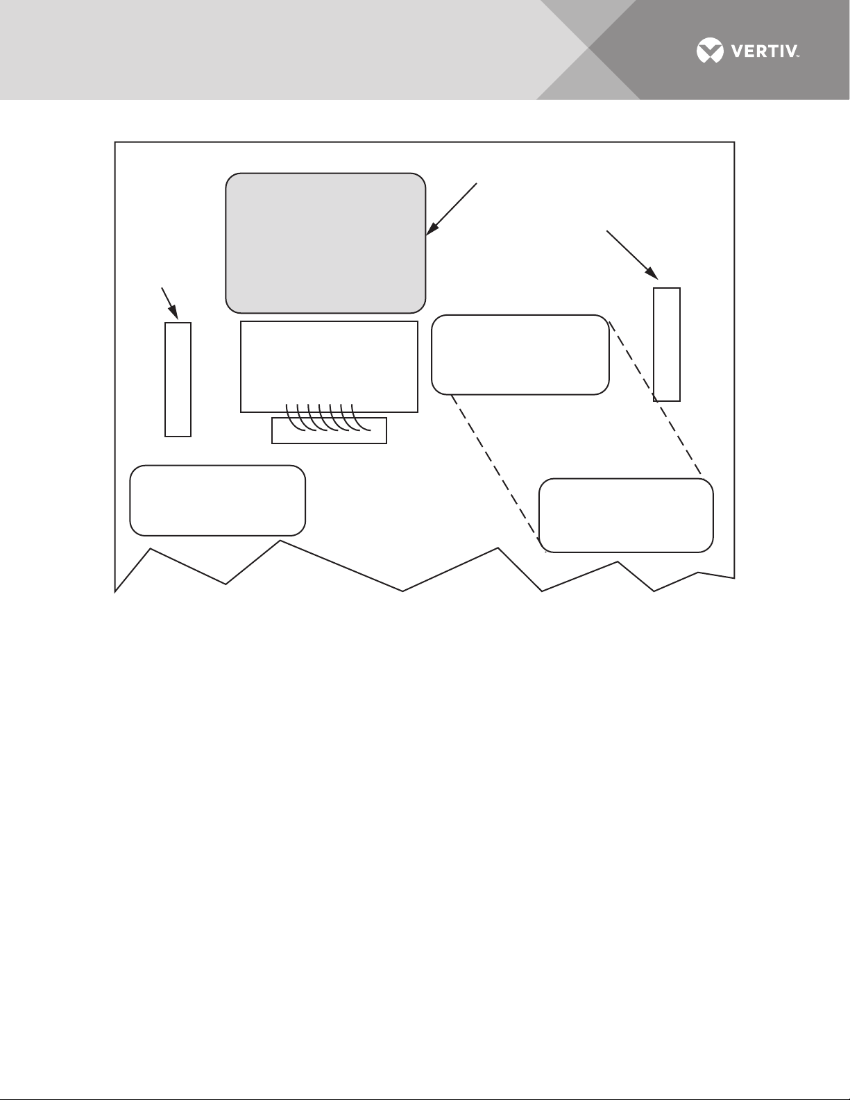
Figure 43 Gate board viewing slot locations
Green LEDs on the Gate
Driver Board viewable
through this slot indicate
that the STS2 is on Source 2.
Green LEDs on the Gate
Driver Board viewable
through this slot indicate
that the STS2 is on Source 1.
Green LEDs on the Gate
Driver Board viewable
through this slot indicate
that the STS2 is on Source 1.
Viewing Slot for
the Source 1
Gate Driver
Board
Viewing Slot for
the Source 2
Gate Driver
Board
Touchscreen
If the Color Graphical Display is not available, you can still use the following bypass procedures, ignore the steps
to check the display and check the LED’s.
If your system contains the LED display, see 14.2.3 - Maintenance Bypass.
Vertiv™ | Liebert® STS2™ 100-1000A, 50/60Hz User Manual | Rev. 12 | 11/2017 65
Page 74

10.4.1 Bypass Procedures for Source 1 To bypass the switch for Source 1:
NOTE
To bypass the Source 1 static transfer switch when Source 2 is presently active, you must first transfer to Source
1. See Manual Transfer / Preferred Source Selection on page 62.
1. Verify that Source 1 is supplying power via the Mimic.
• If the Color Graphical Display is not available, check the gate driver board LED’s through the slots in the control panel.
See Figure 43.
2. Remove the interlock key from CB5 and place it in the CB4 interlock.
3. Open the alternate source input breaker CB2.
4. Rotate and remove the CB2 interlock key.
5. Insert the key in the CB4 bypass breaker interlock.
6. Rotate the interlock keys in the CB4 bypass breaker interlock to retract the interlock.
7. Close bypass breaker CB4.
8. Verify the breaker status on the Mimic screen.
9. Open source input breaker CB1.
10. Rotate the CB1 interlock key and remove it to lock out the breaker.
11. Secure the key according to your site’s lockout/tagout procedure.
12. Open output breakers CB3 and CB3A (if supplied) to remove power and isolate the static switch from the load.
To return to normal mode:
1. Insert the key in the CB1 breaker interlock.
2. Rotate the key to retract the interlock.
3. Close source input breaker CB1.
4. Verify Source 1 and CB1 breaker status on the Mimic screen.
5. Select the SOURCE 1 button in the SOURCE XFERS menu.
6. Close output breakers CB3 and CB3A (if supplied).
7. Verify CB3 and CB3A breaker status.
8. Verify that STS SOURCE 1 and OUTPUT boxes are highlighted on the Mimic screen.
9. Open bypass breaker CB4.
10. Rotate the keys in the CB4 interlock to extend the interlock.
11. Remove the proper key from the CB4 interlock and insert it in the CB2 breaker interlock.
12. Rotate the key to retract the CB2 breaker interlock.
13. Close source input breaker CB2.
14. Verify the STS SOURCE 2 box and CB2 breaker status on the Mimic screen.
• If the Color Graphical Display is not available, check the gate driver board LED’s through the slots in the control panel.
See Figure 43.
Vertiv™ | Liebert® STS2™ 100-1000A, 50/60Hz User Manual | Rev. 12 | 11/2017 66
Page 75

10.4.2 Bypass Procedures for Source 2 To bypass the switch for Source 2:
NOTE
To bypass the Source 2 static transfer switch when Source 1 is active, you must first transfer to Source 2. See
Manual Transfer / Preferred Source Selection on page 62.
1. Verify that Source 2 is supplying power via the Mimic.
• If the Color Graphical Display is not available, check the gate driver board LED’s through the slots in the control panel.
See Figure 43.
2. Remove the interlock key from CB4 and place it in the CB5 interlock.
3. Open the alternate source input breaker CB1.
4. Rotate and remove the CB1 interlock key.
5. Insert the key in the CB5 bypass breaker interlock.
6. Rotate the interlock keys in the CB5 bypass breaker interlock to retract the interlock.
7. Close bypass breaker CB5.
8. Verify the breaker status on the Mimic screen.
9. Open source input breaker CB2.
10. Rotate the CB2 interlock key and remove it to lock out the breaker.
11. Secure the key according to your site’s lockout/tagout procedure.
12. Open output breakers CB3 and CB3A (if supplied) to remove power and isolate the static switch from the load.
To return to normal mode:
1. Insert the key in the CB2 breaker interlock.
2. Rotate the key to retract the interlock.
3. Close source input breaker CB2.
4. Verify Source 2 and CB2 breaker status on the Mimic screen.
5. Select the SOURCE 2 button in the SOURCE XFERS menu.
6. Close output breakers CB3 and CB3A (if supplied).
7. Verify CB3 and CB3A breaker status.
8. Verify that STS SOURCE 2 and OUTPUT boxes are highlighted on the Mimic screen.
9. Open bypass breaker CB5.
10. Rotate the keys in the CB5 interlock to extend the interlock.
11. Remove the proper key from the CB5 interlock and insert it in the CB1 breaker interlock.
12. Rotate the key to retract the CB1 breaker interlock.
13. Close source input breaker CB1.
14. Verify the STS SOURCE 1 box and CB1 breaker status on the Mimic screen.
• If the Color Graphical Display is not available, check the gate driver board LED’s through the slots in the control panel.
See Figure 43.
10.5 Normal System Shutdown
The Liebert STS2 can be shut down from either the static switch mode or the bypass mode.
10.5.1 Shutdown in Static Transfer Switch Mode
When the Liebert STS2 is operating on static transfer switch mode (not maintenance bypass mode):
1. Turn Off the load equipment per manufacturer’s recommendations.
2. Open CB3 to turn Off the static switch output.
• Open CB3A if the static transfer switch has a redundant output configuration.
3. Open the input switches CB1 and CB2.
4. To completely de-energize the unit, turn OFF power to both inputs to the Liebert STS2.
10.5.2 Shutdown in Maintenance Bypass Mode
When the Liebert STS2 is operating on bypass:
1. Turn Off the load equipment per manufacturer’s recommendations.
2. Open the bypass switch (CB4 or CB5) to turn Off the static transfer switch output.
3. To completely de-energize the unit, turn OFF the power to both inputs to the Liebert STS2.
Vertiv™ | Liebert® STS2™ 100-1000A, 50/60Hz User Manual | Rev. 12 | 11/2017 67
Page 76

11.0 ALARM AND FAULTS
Alarms and faults are events that are triggered when the operation of the Liebert STS2 falls outside the defined
parameters. These events can also be triggered by: user actions, such as changing configurations, clearing logs,
etc.; failed components such as a fan failure, an SCR that is open or closed, etc.; and system status, such as open
circuit breakers, load on alternate source, etc. These events can provide a warning or trigger the system to make
a change, such as switch sources or the recording of a history log.
The Liebert STS2 monitoring system detects and annunciates a comprehensive set of fault and alarm
conditions. Faults and alarm messages are can be viewed on the LCD touchscreen or via the RS-232 port.
On the LCD touchscreen, the events are shown in the Status Display panel in the lower left corner of the
touchscreen and written to the Event log. You can touch a message to view a definition of an event and a tip for
troubleshooting. See 13.0 - Liebert STS2 Touchscreen Display for more information on the touchscreen.
If you are monitoring the system through the RS-232 port, see Table 6 - Te rmin a l c o mman d s on page 74 for the
commands to view event logs, and alarm and fault lists.
Event actions can be triggered by the settings configured from the Event Masks. See 11.1 - Event Mask for more
information.
Faults — A fault indicates that a component of the Liebert STS2 has failed or has been damaged. In the Event
Display, faults are indicated in red.
Alarms — An alarm is an event caused by a significant abnormal system condition. In the Event Display, alarms
are indicated in yellow. The setpoints for many of the alarms are configurable through the User Settings. Many
alarms clear themselves when the condition is resolved. If an alarm event mask is set to latch, the alarm
messages remain active until the alarm condition has been corrected and the RESET button is pushed. See 11.1 -
Event Mask for more information on latching.
11.1 Event Mask
The Liebert STS2 gathers, processes and reports faults and alarms, collectively referred to below as events. The
Event Mask dialog box allows you to set the system’s response for specific alarms and faults that are generated.
The following mask types are available for each event:
• Latch — If a latch is enabled for the selected event, that event remains active even if the originating event condition clears.
A latched event may only be cleared by pushing the RESET button (ALRMRST on the LED units).
• Event Log — The selected event is date/time stamped and recorded to the Event Log when the event is triggered.
• Audible — If the selected event is triggered, an audible beeper or horn is sounded by the Liebert STS2. The beeper
continues while this event is active or latched, or until the SILENCE button (NOAUD on the LED units) is pushed. This
button must be pushed with the ALRMRST button on the LED units.
See Event Masks on page 85 for instructions on setting the mask type via the touchscreen display. See the
12.1.4 - Setting Event Masks with the Terminal on page 80 for instructions on configuration using the RS-232
port.
11.2 Event and History Logs
The system tracks events through the Events Log and tracks significant events through the History Logs. These
logs allow you to quickly spot trends or diagnose problems that the unit may have had. Both logs are written in
nonvolatile memory.
The logs can be accessed from the touchscreen menu or the RS-232 port. See 13.11 - Logs for more instructions
on viewing the logs from the touchscreen. See Table 6 - Terminal commands on page 74 for the RS-232
interface commands used to access the logs.
Vertiv™ | Liebert® STS2™ 100-1000A, 50/60Hz User Manual | Rev. 12 | 11/2017 68
Page 77

11.2.1 Event Log
The events are tracked in sequence of occurrence. The sequence of occurrence is identified by date, time, and
frame number. The last 512 events are stored in a nonvolatile memory and can be viewed from the Event Log.
Event logs wrap, meaning when the log is full, the oldest event is deleted when a new event is written to the log.
The Event Log tracks:
• # — the sequence number in which the event occurred since the log was last cleared.
• Message — the event that occurred, such as Ambient Overtemp., Source 1 Fail, etc.
• Type — either a Fault or Alarm. See 11.0 - Alarm and Faults on page 68 for further details on these events.
• ID — the event identifier.
• Date and Time — when the event occurred.
• Faults — the number of fault events logged.
• Alarms — the number of alarm events logged.
• User Alarms — the number of alarm events logged that were triggered by user-created alarms, such as those alarms
created with the Input Contact Isolator settings.
• Total — the sum of all the events currently logged.
11.2.2 History Log
When a designated major alarm occurs, the History Status buffer is frozen, capturing 64 sequential frames
before and after the alarm condition. When the History Status buffer is frozen, a History Log is created.
Two History Logs are available to track major alarms. This log includes the triggering event plus the surrounding
events, and the system voltages, currents, frequency, power, source selection and breaker positions at the time of
the event. The History Log displays the 64 sequential frames, in 4-millisecond intervals, of the Present Status
screens surrounding the event.
If you are viewing the log from the touchscreen, the Mimic and the Event Display show the data that was present
as the alarm was triggered. The data is displayed as frames are played.
The History Log allows you to replay the events leading up to the alarm and the events right after the alarm to
see the status of the switch at that time and diagnose the cause of the alarm. The History Log is triggered when
certain events are tripped that have the Freeze option enabled.
You can run through the frames sequentially. The sequence of the events is identified by date, time, and frame
number. The History Log frames are stored in a nonvolatile memory buffer that is continuously overwritten until
a designated fault condition occurs. When the fault occurs to trigger a freeze, the History Log stores the next 23
frames, then freezes until it is reset. The History Log then keeps 40 frames before the fault, the frame where the
fault occurred, plus the next 23 frames.
The History Log should not be reset until the fault condition that caused the buffer to freeze is reviewed and
investigated by a qualified service technician. After the alarm condition has been corrected, the History Log can
be cleared.
The History Log has the following fields:
• Replay Rate — indicates how long it takes for the replay to play. Use the UP and DOWN buttons to set the time.
• Status — the status of the Liebert STS2 at the point of the current frame in the replay. The History log has three statuses:
Frozen, Not Frozen and Retrieving Data.
• Critical Event — The event which triggered this log to be written. The event is indicated in red on the bar graph.
• Frame Number — the current frame in the replay. A negative number indicates the replay is at a point before the triggering
event occurred.
Vertiv™ | Liebert® STS2™ 100-1000A, 50/60Hz User Manual | Rev. 12 | 11/2017 69
Page 78

11.3 Alarm Notes
The I-PK on Source 1 and I-PK on Source 2 alarms inhibit automatic transfer due to an overload or load fault.
These alarms can be set for either auto or manual alarm reset.
In the auto reset mode, the alarm is reset 100 milliseconds after the load current and source voltage return to
normal, and transfers are no longer inhibited. In manual mode, the alarm remains active and transfers are
inhibited until the conditions return to normal and the user manually presses the RESET button (ALRMRST
button on LED units). In either case, the cause of the Source 1 or Source 2 I-Peak overload should be
investigated and resolved (such as by reducing the overload condition or clearing the output fault) before
returning the switch to normal operation.
SCR fault events indicate a device failure. The device must be replaced and the system must be restarted for the
fault to clear. A shorted SCR automatically trips open a source input switch (CB1 or CB2) to prevent transfers in
the event of an SCR failure. The SCR failure must be investigated and repaired before returning the switch to
normal operation. Both source input switches must be opened (such as when the unit is placed in maintenance
bypass for servicing) before a shorted or open SCR alarm can be reset.
11.4 List of Messages
Tabl e 5 lists available event messages, a definition of the event, and the functions that are activated with the
event by default. The functions are indicated as follows:
A — The indicated event activates the Audible alarm.
F — The indicated event triggers a Freeze of the History Log.
L — The indicated event Latches. A latched alarm remains displayed until the alarm condition has cleared and the RESET
(ALRMRST) button has been pressed.
E — By default, all faults and alarms are written to the Event Log. Changing this setting is only available for the LED units and
is set through the RS-232 port. See Setting Event Masks with the Terminal on page 80
All of these functions, except Freeze, can be reconfigured to trigger for each event, using the Event Mask option.
See 11.1 - Event Mask on page 68. The Freeze function is hard-coded and cannot be changed for an event.
If the front panel of your Liebert STS2 has LED’s and push buttons instead of the touchscreen interface, you can
view these messages via the RS-232 port. See 12.1.1 - Connecting and Using a Terminal on page 74 for the
commands to view the event messages on a PC terminal.
An LED is used to indicate the presence of any active fault or alarm. Refer to 14.0 - Operating the Liebert STS2
LED Display for more information about the LED’s.
.
Vertiv™ | Liebert® STS2™ 100-1000A, 50/60Hz User Manual | Rev. 12 | 11/2017 70
Page 79

Table 5 Event messages
ID Alarm Message Description/Cause Action
001 S1 SCR SHORT One or more of the SCRs for Source 1 have shorted and failed. D, F, A, E
002 S2 SCR SHORT One or more of the SCRs for Source 2 have shorted and failed. D, F, A, E
003 S1 SCR OPEN One or more of the SCRs for Source 1 is open. D, F, A, E
004 S2 SCR OPEN One or more of the SCRs for Source 2 is open. D, F, A, E
005 PRIMARY FAN FAIL
006 CONTROL MODULE FAIL Control logic module has failed. D, A, E
007 PWR SPLY DC A FAIL Power supply DC bus A has failed. D, A, E
008 PWR SPLY DC B FAIL Power supply DC bus B has failed. D, A, E
009 PWR SPLY S1 AC FAIL Power supply Source 1 AC has failed. D, A, E
010 PWR SPLY S2 AC FAIL Power supply Source 2 AC has failed. D, A, E
011 PWR SPLY LOGIC FAIL A power supply module has failed. D, A, E
012 OUT VOLT SENSE FAIL The output volt sense module failed D, A, E
013 S1 VOLT SENSE FAIL The Source 1 volt sense module failed. D, A, E
014 S2 VOLT SENSE FAIL The Source 2 volt sense module failed. D, A, E
015 S1 SCR SENSE FAIL The Source 1 SCR sense module failed. D, A, E
016 S2 SCR SENSE FAIL The Source 2 SCR sense module failed. D, A, E
017 S1 CURR SENSE FAIL The Source 1 SCR current module failed. D, A, E
018 S2 CURR SENSE FAIL The Source 2 SCR current module failed. D, A, E
019 S1 GATE DRIVE FAIL The Source 1 gate drive module failed. D, A, E
020 S2 GATE DRIVE FAIL The Source 2 gate drive module failed. D, A, E
021 INTERNAL COMM FAIL Internal CAN communications failed. D, A, E
022 EXTERNAL COMM FAIL Options CAN communications failed. A, E
023 CB1 SHUNT TRIP FAIL CB1 shunt trip failed. A, E
024 CB2 SHUNT TRIP FAIL CB2 shunt trip failed. D, A, E
064 HEATSINK OVERTEMP Heatsink has exceeded the recommended temperature. A, E
067 S1 UV Source 1 under voltage, fast detection. A, E
068 S1 UV (RMS) Source 1 under voltage, slow detection. L, A, E
069 S1 OV Source 1 over voltage A, E
070 S1 OF/UF Source 1 over frequency/under frequency A, E
071 S1 FAIL Source 1 failure. A, E
072 S2 UV Source 2 under voltage, fast detection. A, E
073 S2 UV (RMS) Source 2 under voltage, slow detection. A, E
074 S2 OV Source 2 over voltage. A, E
075 S2 OF/UF Source 2 over frequency/under frequency. A, E
076 S2 FAIL Source 2 failure. A, E
077 S1 OVERCURRENT Source 1 over current. A, E
078 S2 OVERCURRENT Source 2 over current. A, E
079 S1 I-PEAK I-PK on Source 1. A, F, E
080 S2 I-PEAK I-PK on Source 2. A, F, E
081 SOURCES OUT OF SYNC Source 1 and Source 2 are out of synchronization. A, E
A primary cooling fan has failed and the unit is now being cooled by a
secondary fan, which is not monitored.
D, A, E
Vertiv™ | Liebert® STS2™ 100-1000A, 50/60Hz User Manual | Rev. 12 | 11/2017 71
Page 80

Table 5 Event messages (continued)
ID Alarm Message Description/Cause Action
082 LOAD ON ALT SOURCE The output load is running on the alternate source. A, E
083 AUTO REXFER INHIBIT Automatic retransfer is inhibited. A, E
084 CB1 (S1) OPEN Source 1, Circuit Breaker 1 is open. A, E
085 CB2 (S2) OPEN Source 2, Circuit Breaker 2 is open. A, E
086 CB4 (S1 BYP) CLOSED Source 1 on bypass, Circuit Breaker 4 is closed. A, E
087 CB5 (S2 BYP) CLOSED Source 2 on bypass, Circuit Breaker 5 is closed. A, E
088 CB3 (OUTPUT) OPEN Output circuit breaker (CB3) is open. A, E
089 CB3A (OUTPUT) OPEN Output circuit breaker (CB3A) is open. A, E
090 S1 PHASE ROT ERROR Source 1 phase rotation error. A, E
091 S2 PHASE ROT ERROR Source 2 phase rotation error. A, E
092 TRANSFER INHIBITED Transfer inhibited. A, E
093 OUTPUT UV Output is under voltage. D, F, A, E
INPUT CONTACT #1
120
INPUT CONTACT #2
121
INPUT CONTACT #3
122
INPUT CONTACT #4
123
INPUT CONTACT #5
124
INPUT CONTACT #6
125
INPUT CONTACT #7
126
INPUT CONTACT #8
127
128 CONFIG MODIFIED A set point configuration has changed. A, E
129 PASSWORD CHANGED The password for touchscreen access has been modified and saved. A, E
130 TIME REPROGRAMMED The system’s time has been reset and saved. A, E
131 DATE REPROGRAMMED The system’s date has been reset and saved. A, E
132 EVENT LOG CLEARED The event log has been erased. A, E
133 HIST LOGS CLEARED Both History Logs have been erased. A, E
134 HIST LOGS FULL
Input Contact # x is an optional alarm input. The alarm name can be
programmed with an alarm name from the Input Contactor Isolator
settings option under the Comm Options. See Configuring the Input
Contact Isolator Settings on page 91. The alarm is sent to Monitor DSP.
The LCD logs the alarm with the programmed name. Monitor DSP logs it
with the generic name which is how it is reported to the SVT query.
Both History Logs have been written and no more history logs can be
written without clearing one of the logs.
A, E
A, E
Vertiv™ | Liebert® STS2™ 100-1000A, 50/60Hz User Manual | Rev. 12 | 11/2017 72
Page 81

12.0 COMMUNICATION INTERFACES
The Liebert STS2 monitoring system offers several choices for communications.
The RS-232 terminal port is standard on all units. The port is located inside the front door, to the left of the
touchscreen/LED front panel mounting as shown in Figure 26. This port is primarily used as an alternate user
interface to configure, control, and diagnose the system, especially for systems that do not include the HMI
touchscreen. Commands for the RS-232 port are shown in Tab le 6 .
Several other communications options are also available. Those options are located a Communications
compartment to the right of the touchscreen/LED front panel and are accessible when the front panel door is
open. See Figures 19 and 20 for the location of the communications options.
Connections to the communication ports are made by wiring to terminal boards located in the Communications
compartment. The communications options listed below reference the control wiring drawing for each option.
• Liebert IntelliSlot SNMP/Web/Modbus 485 card (optional) — the card provides connectivity to any TCP/IP-based Ethernet
network to allow the device to communicate with network management systems (NMS) via SNMP/Web(HTTP). Events can
be transmitted to the NMS to provide remote status monitoring, plus fault and alarm detection. The card includes an RJ-45
port for an Ethernet connection, via Category 5 cable.
The Liebert SNMP/Web/Modbus 485 card can also integrate the system with an existing Building Management System
(BMS) or out-of-band monitoring, using Modbus, a standard multi-drop protocol. The card has redundant communication
paths that make it possible to connect to a BMS using Modbus while simultaneously communicating to an NMS through
SNMP/Web(HTTP).
See Figure 25 for more information on the Liebert SNMP/Web/Modbus 485 card. If you have questions about the card,
refer to the user guide, SL-52615, available at the Liebert Web site, www.vertivco.com
• Input Contact Isolator (ICI) Board (optional) — provides an interface for up to eight user inputs. External messages and
alarms can be routed to the unit, via the ICI.
See Configuring the Input Contact Isolator Settings on page 91 for instructions on configuring the connections. See
Figure 23 for wiring details.
• Programmable Relay Board (PRB) (optional) — up to two PRB’s can be installed in the Liebert STS2 to route Liebert STS2
events to external devices.
See Configuring the Programmable Relay Board Settings on page 92 for default settings and instructions for
reconfiguring the relays. See Figure 22 for wiring details.
• Comms Board (optional) — provides a direct connection to a Liebert SiteScan terminal, via an RS-422. Liebert SiteLink-12 or
Liebert SiteLink-4 is required for Liebert SiteScan to communicate with the Liebert STS2. See Figure 24 for wiring details.
Data link requirements are Full Duplex Asynchronous RS-232 format.
Communications options are also discussed in 6.0 - Options.
12.1 Using the RS-232 Port
The RS-232 port is configured with a baud rate of 9600 with 8 data bits, 1 stop bit, no parity, and no hardware
handshaking.
Vertiv™ | Liebert® STS2™ 100-1000A, 50/60Hz User Manual | Rev. 12 | 11/2017 73
Page 82

12.1.1 Connecting and Using a Terminal
Repeating command -->
Illegal command!
<?> or <HELP?> displays the RS-232 command set
<?> <command> or <HELP?> <command> displays specific help for the command
SVTP-Control >
An RS-232 connection can be used to connect the Liebert STS2 to either a terminal or a PC running terminal
emulation software. If you are unsure of the cable pin out, see 15.2.10 - Terminal Port Connections.
1. Connect the terminal to the Liebert STS2 by plugging the cable from the terminal into the RS-232 port.
This connection can be made at any time.
2. After making the connection, verify the communications link by pressing <ENTER> on the terminal keyboard.
The interface communications system responds as indicated below:
The SVTP-Control > prompt indicates that RS-232 communications are established.
• If you receive no response or prompt, verify that the connector is properly plugged into the port and the PC or terminal
serial interface is working properly.
3. Enter the desired commands, as listed in Tab le 6 .
For additional help type <?> <command> or <HELP?> <command>
Refer to the corresponding menu options in 13.0 - Liebert STS2 Touchscreen Display for more details about
the commands.
Some terminal commands require a password to function. Use the PWD command and a valid password to gain
access.
Table 6 Terminal commands
Keys Function
? Displays this help menu or specific help with a command
AA? Displays active alarms
AF? Displays active faults
CEL Clears the event log
CHL Clears the history logs
DATE? Displays current system date
DATE Sets system date
EL? Displays the entire event log
HELP? Displays this help menu or specific help with a command
HLn? Displays the history log #n, if frozen
LOGOUT Logs user out of unprotected mode
PS? Displays the preferred source
PS n Sets the preferred source to #n
PWD Allows users to access protected commands
SH Silences the horn
SPT? Displays all current setpoints
SPTx
SR? Displays status reports
TIME? Displays current system time
TIME Sets system time
UPMDR? Displays metering data
VER? Displays firmware versions
Vertiv™ | Liebert® STS2™ 100-1000A, 50/60Hz User Manual | Rev. 12 | 11/2017 74
Displays current setpoints for group x. See 12.1.2 - Configuring the Liebert STS2 via the Terminal
for a description of groups.
Page 83

12.1.2 Configuring the Liebert STS2 via the Terminal
The SPT command is used to configure the systems setpoints. The SPT syntax for the setpoints consists for four
parameters:
SPT [group] [item] [value]
where the parameters are:
• SPT — is the terminal command that is used to configure setpoints.
• group — the group under the setpoint command which contains the desired settings.
• item — the item number within the selected group.
• value — the desired value for this item.
Only the specific options words listed in this section use a hexadecimal value. Other settings, depending on what
they are, use other input types. For example, System ID uses a text string, nominal voltages and currents use
standard numeric integers.
NOTE
Spaces are placed between each parameter, but not between characters or numbers in a parameter. Using an
underline here to represent a space, an example of a the syntax is: SPT_2_6_0081. 0081 is the value parameter.
This section provides instructions for setting these parameters, with an example of building an SPT command
for System and User settings.
Groups Parameter
The setpoints are grouped for ease of configuration. For example, Event Masks are Group 4 and System Settings
are Group 2. The numbers shown below are entered for the group parameter. For example, start of a System
Settings command is SPT 2.
The group parameters are:
1 = System Ratings
2 = System Settings
3 = User Settings
4 = Event Mask Settings
For example, the start of a System Settings command is SPT 2, where SPT is the system setpoints command and
2 is the group parameter for System Settings.
See 12.1.4 - Setting Event Masks with the Terminal on page 80 for instructions on configuring Event Mask
parameters.
Item Parameter
Each setting within the group is indexed by an item number as shown below in Tab le 8. These item numbers are
also displayed on the terminal when you list the configuration setting for a particular group.
Continuing with the example, to configure an Options_1 setting under System Settings, the command would
begin with SPT 2 6
where 6 is the value Options_1. Note the space between each parameter.
Vertiv™ | Liebert® STS2™ 100-1000A, 50/60Hz User Manual | Rev. 12 | 11/2017 75
Page 84
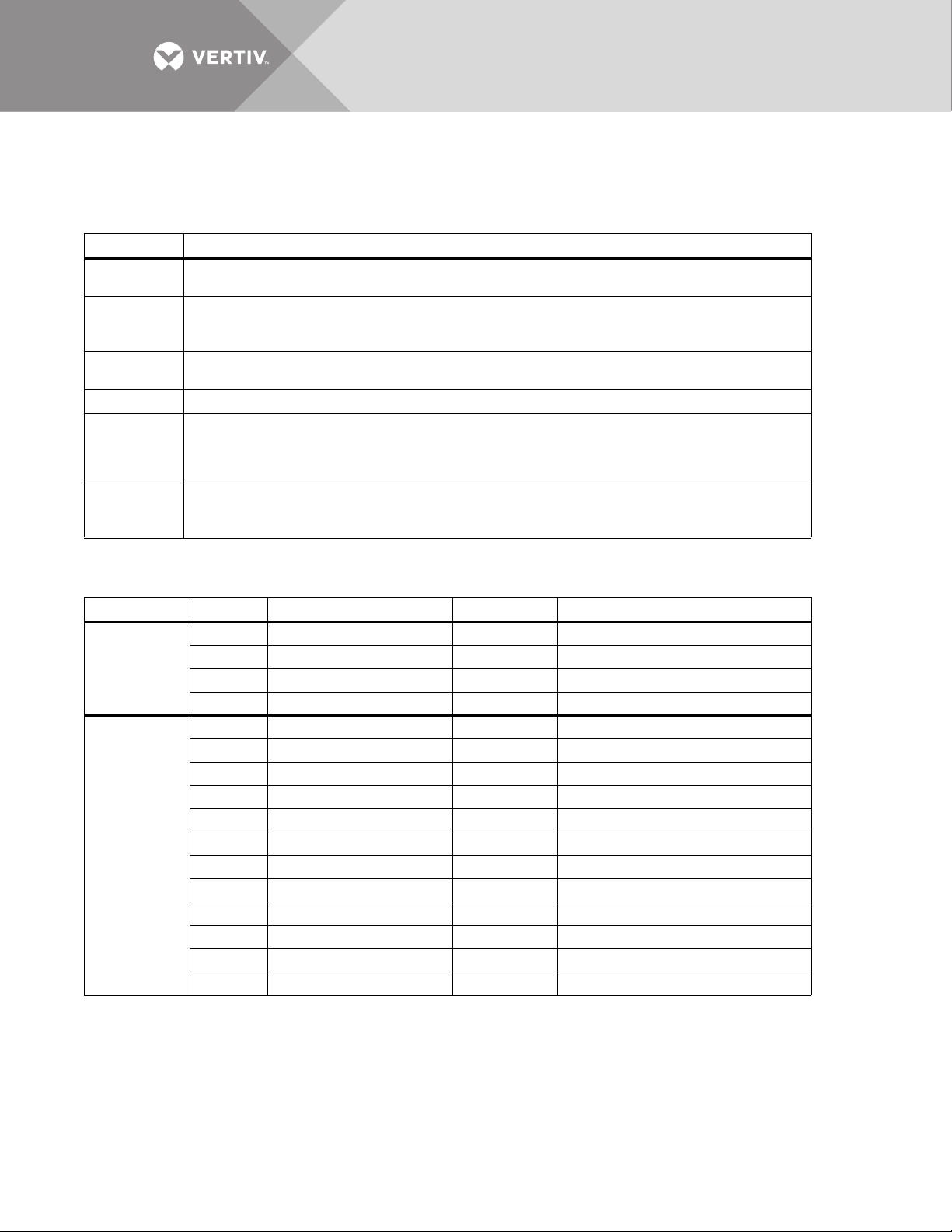
Value Parameter
Item settings, depending on what they are, use various value types. Tab le 7 provides a list of the possible value
types and their description.
Table 7 Value types
Type Definition
Numeric
Scaled
String
Enumeration This type uses an indexed list to represent possible choices.
Bit-packed
Event Masks
An integer numeric value in the units indicated by the item name. For example, a System Voltage Rating of 480
would indicate 480 volts.
Similar to the Numeric, this value type is an integer that has been scaled, usually to remove decimal points that
would normally appear within the value. In this case, a value of 2.5 may actually be input as simply 25. For all
Scaled types, the scaling appears in Ta bl e 8 .
Certain settings are represented by alphanumeric character strings, such as setting the System Model Number to
Liebert STS2.
This type of value uses a hexadecimal binary word, where each of the sixteen bits in the word has the value of 1
(True) or 0 (False). Although somewhat difficult to use, it packs a large amount of data within a single entry. A
detailed description of this type appears in section 12.1.3 - Setting Bitpacked Options with the Terminal on
page 78.
This type is a specially formatted and is used to customize the behavior of each fault and alarm in the system. See
12.1.4 - Setting Event Masks with the Terminal on page 80 for instructions on configuring Event Mask
parameters.
Tabl e 8 shows the various groups, the settings contained within, and the type of value it requires.
Table 8 Group sett i n g s a n d values
Group Item Description Value Type Value Notes
1 Input Volts (PDU) Integer Set per system spec.
Group 1:
System
Ratings
Group 2:
System
Settings
2 Volts Integer Set per system spec.
3 Current Integer Set per system spec.
4 Frequency Scaled Desired freq. x 10 (600 = 60 Hz)
1 Language Enumeration [Not supported at this time]
2 System Model Number String 14 Character max.
3 System ID Number String 8 Character max.
4 System Tag Number String 8 Character max.
5 System Order Number String 8 Character max.
6 Options_1 Bitpacked 14 Character max.
7 Autodial Primary Line String 20 Character max.
8 Autodial Secondary Line String 20 Character max.
9 Autodial Pager Number String 20 Character max.
10 Autodial Pager PIN String 10 Character max.
15 Comms Options 1 Bitpacked See section 12.1.3.
16 Comms Options 2 Bitpacked See section 12.1.3.
Vertiv™ | Liebert® STS2™ 100-1000A, 50/60Hz User Manual | Rev. 12 | 11/2017 76
Page 85

Table 8 Group sett i n g s a n d values (continued)
Group Item Description Value Type Value Notes
SCR1 Fast Undervoltage
Setpoint
SCR1 Slow Undervoltage
Setpoint
SCR1 Slow Undervoltage
Detect Delay
SCR1 Overvoltage Detect
Delay
SCR2 Fast Undervoltage
Setpoint
SCR2 Slow Undervoltage
Setpoint
SCR2 Slow Undervoltage
Detect Delay
SCR2 Overvoltage Detect
Delay
Integer In % of nominal below nominal
Integer In % of nominal below nominal
Integer In number of lines cycles
Integer In 1/4 lines cycles
Integer In % of nominal below nominal
Integer In % of nominal below nominal
Integer In number of lines cycles
Integer In 1/4 lines cycles
Group 3: User
Settings
Group 4: Event
Mask Settings
1
2
3
4 SCR1 Overvoltage Setpoint Integer In % of nominal above nominal
5
6 SCR1 I peak Transfer Setpoint Integer x 10
7
8
9
10 SCR2 Overvoltage Setpoint Integer In % of nominal above nominal
11
12 SCR2 I peak Transfer Setpoint Integer x 10
13 Max. Transfer Phase Angle Integer In degrees
14 Output Frequency Deviation Integer Freq. in Hz x 10
15 Retransfer Delay Time Integer In seconds
16 Horn Volume Integer Range: 1-10
17 Critical Option Enabling Bitpacked See section 12.1.3.
18 Non-Critical Option Enabling Bitpacked See section 12.1.3.
1 to 63 Event Mask settings for faults Event Mask See section 12.1.4.
64 to 143 Event Mask settings for alarms Event Mask See section 12.1.4.
Vertiv™ | Liebert® STS2™ 100-1000A, 50/60Hz User Manual | Rev. 12 | 11/2017 77
Page 86

12.1.3 Setting Bitpacked Options with the Terminal
Five sets of options and features settings are available through the terminal to control the system operation.
Under System Settings for the SPT command, these items denote which options are INSTALLED:
•6 — Options_1
• 14 — Comms Options 1
• 15 — Comms Options 2
Under User Settings, for the SPT command, these items denote which features are ENABLED:
• 17 — Critical Option Enabling
• 18 — Non-Critical Option Enabling
The value parameter settings are in the form of a bit-packed word (in hexadecimal notation). In other words,
each bit indicates a particular setting for the option or feature. The bit assignments for the options and features
are as follows:
Options_1
bit0 — HasDualOutputBreaker
bit1 — HasPDU
bit2 — Has4PoleTransferSwitch
bit3 — HasShuntTrip
bit4 — HasWyeOutputXfmr
bit5 — HasExternalPrecisionTimeSource
bit6 — HasSFA
bit7 — HasRemoteSourceSelect
bit8 through bit15 — not used (set to 0)
Comms Options 1
bit2 — HasNIC
bit3 — not used (set to 0)
bit4 — HasSiteScan
bit5 — not used (set to 0)
bit6 — not used (set to 0)
bit7 — HasOpenCommsDigitalInputBrd
bit8 — HasOpenCommsDigitalOutputBrd_1
bit9 — HasOpenCommsDigitalOutputBrd_2
bit10 — HasRemoteStatusPanelBrd_1
bit11 — not used (set to 0)
bit12 — not used (set to 0)
bit13 — not used (set to 0)
bit14 — EnableDialIn
bit15 — EnableDialOut
Comms Options 2
bit0 — EnablePager
bit1 — EnableOCDINormallyClosed
bit2-3 — OCDO1Assignment (0=User Defined, 1=Standard Set or 2=AS400)
bit4-5 — OCDO2Assignment (0=User Defined, 1=Standard Set or 2=AS400)
bit6 through bit15 — not used (set to 0)
Critical Option Enabling
bit0—EnableManual_IPeakReset
bit1—EnableAutoRestart
bit2 through bit15 - not used (set to 0)
Vertiv™ | Liebert® STS2™ 100-1000A, 50/60Hz User Manual | Rev. 12 | 11/2017 78
Page 87

Non-Critical Option Enabling
bit0 — EnableAutoReXfer
bit1 through bit15 — not used (set to 0)
The bits are set in reverse order, from bit 15 on the left to bit 0 (zero) on the right. The bits are grouped in four
sets of four bits each, as such:
0000 0000 0000 0000
|................................|
bit 15.........................bit 0
Since each bit represents a setting, a bit can be enabled or disabled:
• 1 = installed option or enabled feature
– or –
•
0 = option not installed or feature not enabled
Enabling or disabling the bits in each group creates a binary value for that group. For example, if the fourth bit in
a group is set to 1, the group group’s binary value is 0001.
Each group is translated into a hexadecimal equivalent. The group with the value of 0001 has a hex equivalent of 1.
You can use this table to help with the conversion:
Table 9 Binary-hexadecimal conversions
Binary Value Hex Equivalent Binary Value Hex Equivalent
0000 0 1010 A
0001 1 1011 B
0010 2 1100 C
0011 3 1101 D
0100 4 1110 E
0101 5 1111 F
0110 6
0111 7
1000 8
1001 9
The hex value for each group is entered in the command as four digits.
To summarize the procedure:
1. Set each bit position.
2. Convert the binary value each group into its hex equivalent.
3. Enter the hex values for each group, in order, into the command for the value parameter.
The following example explains how the conversion is completed.
Vertiv™ | Liebert® STS2™ 100-1000A, 50/60Hz User Manual | Rev. 12 | 11/2017 79
Page 88

Putting the Terminal Command Together
For example, a unit only has the Remote Source Selection and Dual-Output Breaker options installed.
Checking the bits list under Options_1 on page 78, bits 7 and 0 each must be set to 1 to indicate that these
options are installed.
The bit setting is as follows, starting with bit 15 on the left and going down to bit 0:
0000 0000 1000 0001
With the bits combined in groups of four, the binary settings can be translated into hexadecimal values.
The first two groups in the sample equal zero (0). In the third group, 1000 in binary translates to 8 in hex. In the
fourth group, 0001 in binary translates to 1 in hex.
In hex this equates to (digits in the value parameter cannot have spaces between them):
0081
So your command to indicate that the Remote Source Selection and the Dual-Output Breaker are installed would
be:
SPT 2 6 0081
12.1.4 Setting Event Masks with the Terminal
The event masks can be customized via a terminal. The command SPT4?<ENTER> displays all faults and alarms,
along with their associated event masks. A plus sign (+) means that particular event mask is enabled, while a
minus sign (-) means that mask is disabled.
Refer to 11.1 - Event Mask on page 68 for more information on event masks and their associated flags.
Unlike the System and User Settings, mask values are set by designated letters, not hex values. However, as with
other RS-232 interface settings, four parameters are passed. See 12.1.2 - Configuring the Liebert STS2 via the
Terminal on page 75 for more details about the parameters.
The syntax for configuring event masks is:
SPT 4 ID ±D±L±S±E±A
• SPT — is the terminal command used to configure setpoints.
• 4 — setting (group parameter) for event masks, under System Settings.
• ID — event ID. The ID is the item parameter for this command. The ID numbers for each event are listed with the events in
Table 5 on page 71.
• D,L,S,E,A — the event masks: Dial, Latch, Summary, Event log, and Audible. The masks are the value parameter for the
command.
Each mask type must be preceded by a plus sign (+) to enable it, or a minus sign (-) to disable it.
NOTE
NO spaces are placed between each mask listed above.
Only the mask that is passed (enabled) is applied when the event occurs.
Note that the Summary and Event Log event masks are only configurable for the LED units.
To set the event masks for a particular event:
1. Enter the command. Examples and descriptions are provided below.
2. Press ENTER.
After the new settings are entered, the new results for that event ID are displayed.
Vertiv™ | Liebert® STS2™ 100-1000A, 50/60Hz User Manual | Rev. 12 | 11/2017 80
Page 89

Examples of Event Mask Settings
• To latch event #001, S1 SCR SHORT, use SPT 4 1 +L.
• To disable event #128, CONFIG MODIFIED, from sounding the horn, use SPT 4 100 -A.
• To enable event #012, OUT VOLT SENSE FAIL, to Dial and go into the Event Log, use
SPT 4 12 +D+E.
• To disable all masks for event #120, INPUT CONTACT #1, use SPT 4 120 -D-L-S-E-A.
To breakdown this syntax for the last example:
•SPT — SVT command
• 4 — group parameter, identifying System Setting group under which the Event Mask settings reside.
• 120 — item parameter. In this command, that is the event ID.
• -D-L-S-E-A — value parameter. In this case, the minus sign (-)disables all masks for the INPUT CONTACT #1 event.
Vertiv™ | Liebert® STS2™ 100-1000A, 50/60Hz User Manual | Rev. 12 | 11/2017 81
Page 90
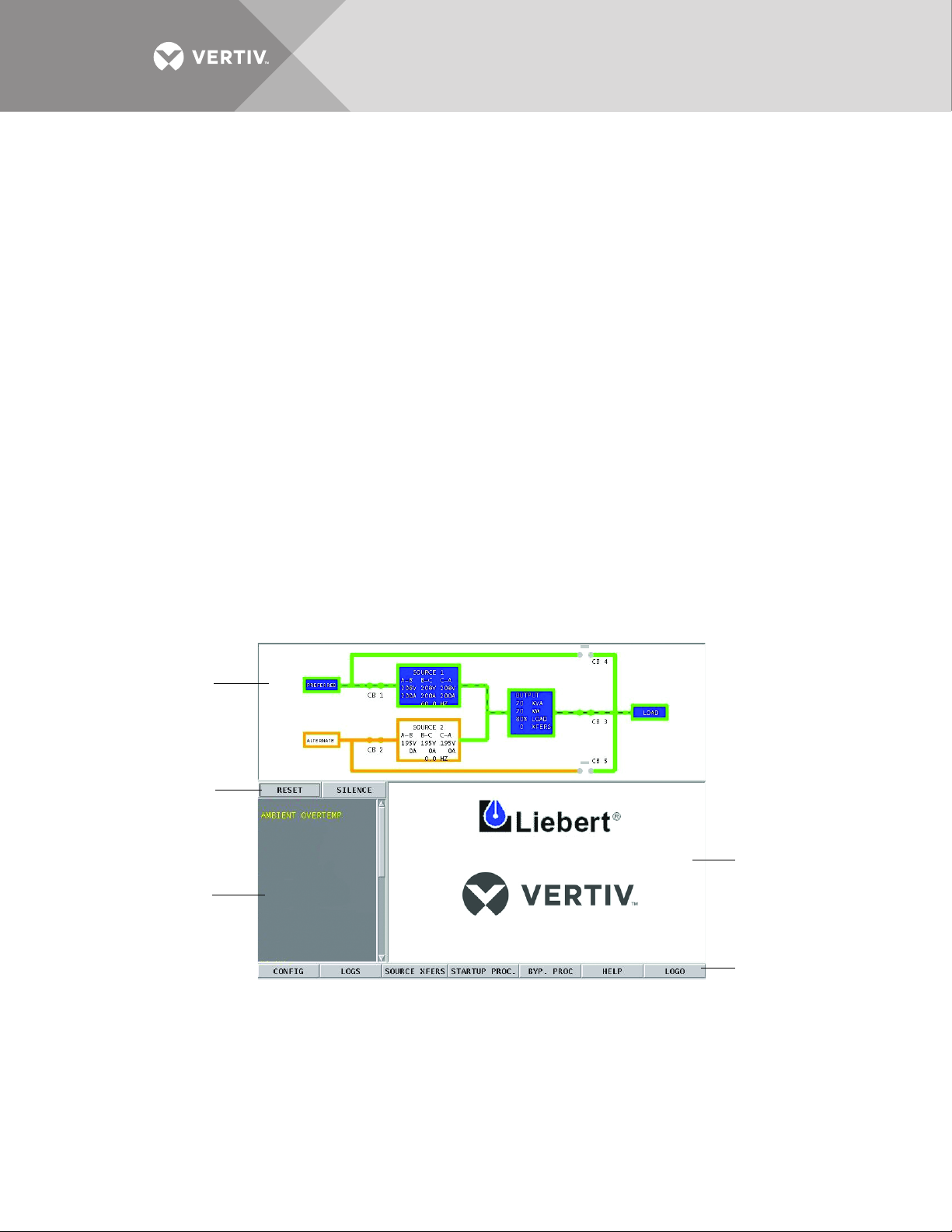
13.0 LIEBERT STS2 TOUCHSCREEN DISPLAY
Mimic
Event Display
Event Controls
Display Panel
Menu Options
The Liebert STS2 can be configured with a Color Graphical LCD touchscreen that allows you to quickly check
the status of the unit and identify problems.
A touchscreen LCD is available through the front of the Liebert STS2. This screen provides a graphical (Mimic)
display of the switch’s operation, plus system information including system parameters, alarms and faults.
The LCD provides a color, back-lit touchscreen as a user interface. In addition to the Mimic and the system
parameters, the screen provides a series of menus to allow you to configure the Liebert STS2, including the
control of the preferred source, auto/manual retransfer selection, alarm notification, and other system setpoints.
The touchscreen also provides buttons to reset alarms and turn Off audible alarms, such as a horn.
13.1 Display Overview
The Liebert STS2 Color Graphical Display provides three areas of information, plus buttons and a series of menu
choices.
The Color Graphical Display contains the following features:
• Mimic — a graphical diagram of the status of the unit.
• Event controls — allow you to reset alarms and turn Off audible alarms.
• Event Display — displays any active alarm or fault condition, in real-time.
• Menus — provide choices and configuration settings in dialog boxes or information in the display panel.
• Display panel — provides additional information, depending on the menu choice that was last selected. This information
includes event help text and startup and bypass procedures.
Figure 44 Liebert STS2 touchscreen display
Vertiv™ | Liebert® STS2™ 100-1000A, 50/60Hz User Manual | Rev. 12 | 11/2017 82
Page 91
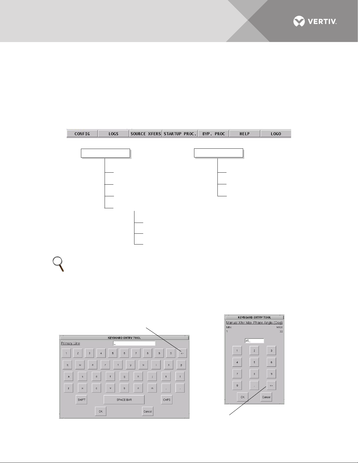
13.2 Menu Overview
Config menu
System Rating
Event Masks
User Settings
Comm Options
System Options
System ID
System Settings
Logs
Event Log
History Log 1
History Log 2
Backspace
Backspace
The touchscreen menu provides access to configuration settings and more device information.
The CONFIG (Configuration) and LOGS menus provide multiple choices through pop-up menus. The SOURCE
XFER menu selection allows you to select the preferred source. The other menu choices provide information in
the display panel. The menu choices are discussed later in this manual.
All programmable functions are preset at the factory to default settings. These settings enable the unit to be
brought up without the need to enter all selectable parameters. The menus allow the settings to be customized.
Figure 45 Menus
NOTE
Some menu choices display a keyboard or keypad on the touchscreen. Enter data on the touchscreen.
Click OK to save the data that you have entered.
Use the back arrow button (<-) to delete unwanted characters. This button functions like a backspace
key on a keyboard.
Figure 46 Keyboard and keypad displays
Vertiv™ | Liebert® STS2™ 100-1000A, 50/60Hz User Manual | Rev. 12 | 11/2017 83
Page 92
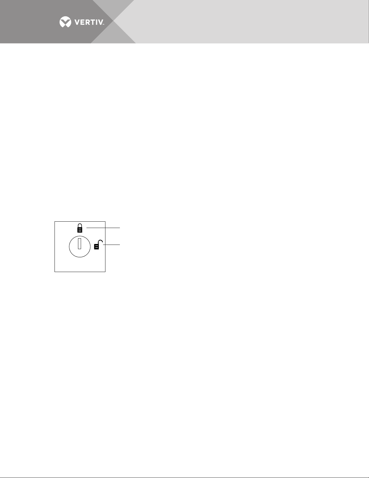
13.2.1 Security
Changes disabled
Changes enabled
Because the Liebert STS2 Color Graphical Display provides access to various configuration and monitoring
choices, a password or key lockout switch may be used to protect access to certain changes, including:
• Change configuration settings.
• Clear logs.
• Make a source transfer.
• Reset an alarm.
Without entering the password or enabling changes with the key lockout switch, you still can:
• View the display, including the mimic, status and event help.
•View logs.
• View the startup and bypass procedures.
• Use the SILENCE button to turn Off the audible alarm.
Using the Optional Key Lockout Switch
An optional key lockout switch for the Liebert STS2 enables or disables the ability to make changes on the
Liebert STS2. The key lockout switch is mounted on the front door. See Figures 7 through 9 for location of the
key lockout switch.
• To disable the changes, turn the key to the top of the switch, toward the closed padlock.
• To enable changes turn the key to the horizontal position, toward the open padlock.
Figure 47 Key lockout switch.
Using the Password
If the unit is not equipped with a keylock, a password is required when you attempt to:
• Save changes in the CONFIG menu choices.
• Transfer sources.
• Reset active alarms.
• Clear logs.
When a password is requested, a keyboard is displayed on the touchscreen. After you enter the password, select
OK.
The password is case-sensitive. Password access times out after ten (10) minutes, and must be re-entered to
save changes. The time-out period cannot be changed.
To set or reset the password:
1. Select SYSTEM SETTINGS from the CONFIG menu.
2. Select SYSTEM ID form the SYSTEM SETTINGS menu.
3. Click PASSWORD.
A keyboard is displayed.
4. Enter a password.
The password must be four (4) alpha-numeric characters and is case sensitive.
5. Click OK.
Vertiv™ | Liebert® STS2™ 100-1000A, 50/60Hz User Manual | Rev. 12 | 11/2017 84
Page 93
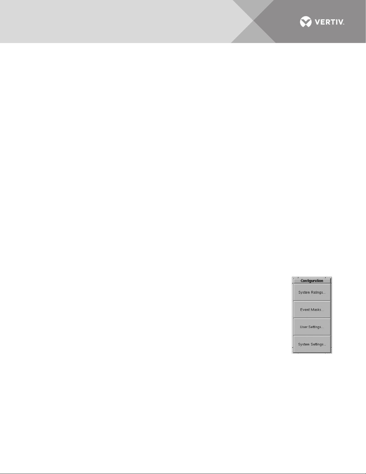
13.3 Mimic Display
The Mimic display provides a color diagram of the operation of the Liebert STS2. This display imitates the power
flow through the static transfer switch and indicates source status, breaker status, switch status, source voltage
and current readings, output power measurements, and active alarm messages. See Figure 44 on page 82.
13.4 Event Controls
The Liebert STS2 detects events when certain thresholds are passed or certain problems occur. The alarm
controls allow you to acknowledge the existence of these events.
• RESET — All latched events whose conditions have cleared are removed from the Event Display. Faults and alarms that
remain active, or are not recoverable, are not affected when this button is selected. This button is also used to perform
manual I-Peak resets and manual retransfers.
• SILENCE — turns Off the audible alarm (horn or beeper) without resetting the triggering event. This setting does not
permanently turn Off the horn. The alarm sounds again when the next event with an audible alarm setting is triggered.
Active events are shown in the Event Display, whereas cleared events can be reviewed via the Event Log.
13.5 Event Display
The Event Display lists the condition of the Liebert STS2 in real-time. Both nominal system parameters and alarm
messages are displayed in the Event Display. You can touch any message in the Event Display to display more
information in the Display Panel to the left. The selected status is displayed in bold type.
13.6 Menu Bar
As previously mentioned, the menu bar provides both configuration choices and information. The choices under
the Config and Log menus access additional dialog boxes, while the other menu choices only show information
in the display panel.
13.7 Configuration Menu
When you select the CONFIG (Configuration) menu choice, a pop-up menu is displayed with
four choices.
• System Ratings — used to configure frequency, voltage and currents settings for the Liebert STS2.
• Event Mask — allows you to configure system’s response for events.
• User Settings — allows you to configure operations for the Liebert STS2.
• System Settings — accesses another pop-up menu to configure communication and system choices
and the system ID.
Each choice accesses a separate dialog box.
13.7.1 System Ratings
The System Ratings menu is used to set the nominal line frequency, nominal voltage and
nominal current at which the system operates when it is installed. These settings are configured when the
system is initialized at the factory or under maintenance and should not be changed by the user.
13.7.2 Event Masks
The Liebert STS2 gathers, processes and reports faults and alarms, collectively referred to below as events. The
Event Mask dialog box allows you to set the system’s response for specific alarms and faults that are generated.
See 11.0 - Alarm and Faults for more information on events and 11.1 - Event Mask for the definitions of the
Event Mask types.
Vertiv™ | Liebert® STS2™ 100-1000A, 50/60Hz User Manual | Rev. 12 | 11/2017 85
Page 94
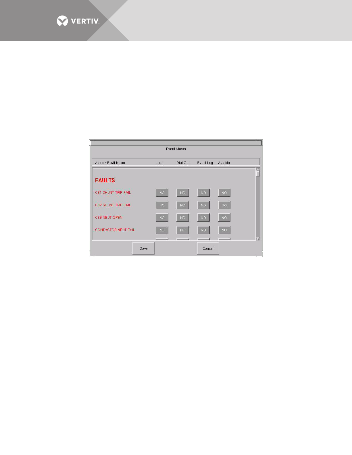
To set the event masks:
1. Access the Event Mask dialog box:
a. Select CONFIG.
b. Select EVENT MASK from the pop-up menu.
The Event Mask dialog box is displayed. See Figure 48.
2. Select the mask settings for each fault and alarm.
a. Select YES to enable the setting,
– or –
b. Select NO to disable the setting.
3. Select SAVE to keep the settings.
Figure 48 Event mask dialog box
13.7.3 User Settings
The User Settings choice allows you to adjust the user-accessible switch settings. Access is limited to qualified
personnel via system security.
To access the User Settings dialog box:
1. Select CONFIG.
2. Select USER SETTINGS from the pop-up menu.
The User Settings dialog box is displayed. See Figure 49. The top six buttons access a series of secondary
dialog boxes to configure the various settings.
Vertiv™ | Liebert® STS2™ 100-1000A, 50/60Hz User Manual | Rev. 12 | 11/2017 86
Page 95
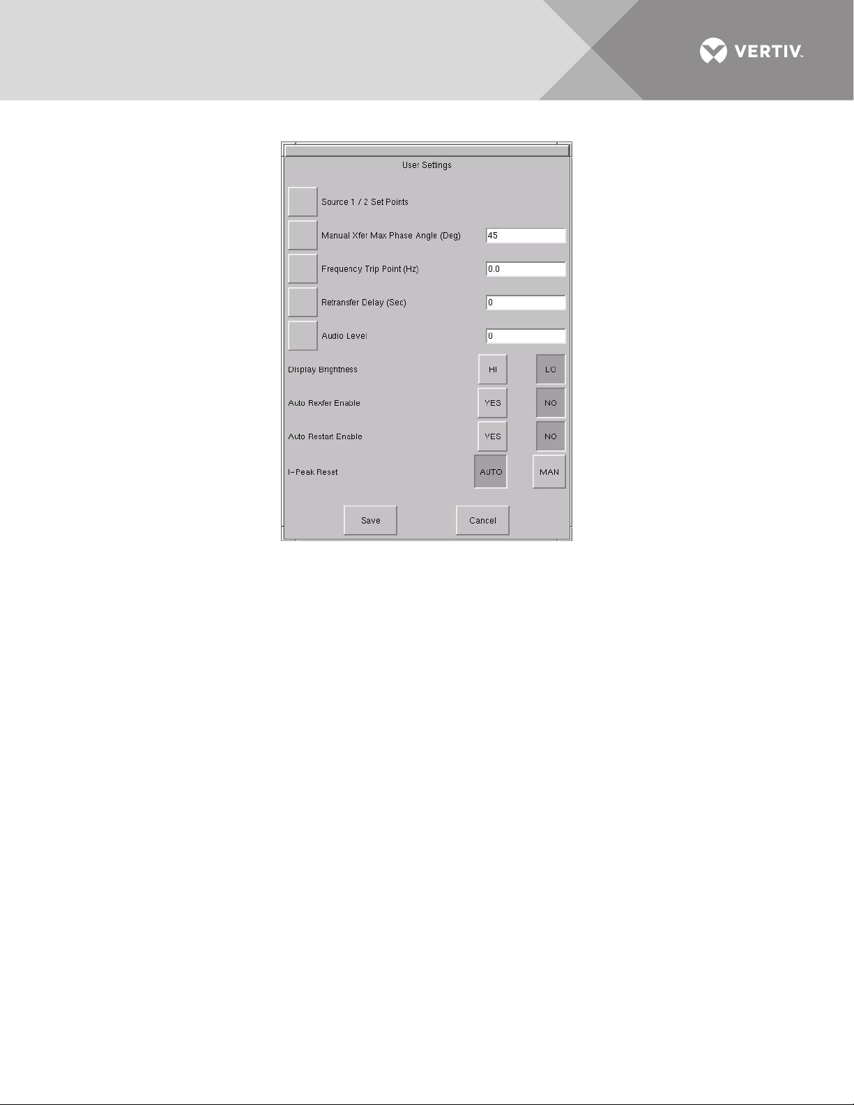
Figure 49 User settings dialog box
Source Set Points
The Source 1/2 Set Points allows you to configure trigger points for each input source (1 or 2) for the Liebert
STS2 via a keypad dialog or HI/LO dialog box. The source numbers do not designate the source as the preferred
or alternate source. The numbers simply identify the input source. See 10.2 - Manual Transfer / Preferred
Source Selection to set the preferred source.
The Set Points are based on values in relation to the nominal voltage required for the Liebert STS2. UV refers to
under voltage, meaning the amount of voltage below the nominal voltage. OV refers to over voltage, or the
amount of voltage over the nominal voltage.
• Fast UV Setting (%) — if the voltage drops below this set percentage of the nominal voltage, the Liebert STS2 transfers
from the current source to the opposite source.
• Slow UV Setting (%) — if the voltage remains this set percentage below the nominal voltage for the period of the slow
detection delay, the Liebert STS2 transfers from the current source to the opposite source.
• Slow UV detection delay — the number of cycles that the source must remain below the Slow UV Setting before the Liebert
STS2 transfers.
• OV Setting (%) — if the voltage exceeds this set percentage of the nominal voltage for the period of the OV detection delay,
the Liebert STS2 transfers from the current source to the opposite source.
• OV Detection Delay — the number of cycles that the source must remain above the OV Setting before the Liebert STS2
transfers sources.
• I-PK Xfer Lockout — if current from the source exceeds this threshold, the Liebert STS2 disables source transfers, and has
to be reset either manually or automatically. The type of reset is configured under the User Settings.
Vertiv™ | Liebert® STS2™ 100-1000A, 50/60Hz User Manual | Rev. 12 | 11/2017 87
Page 96
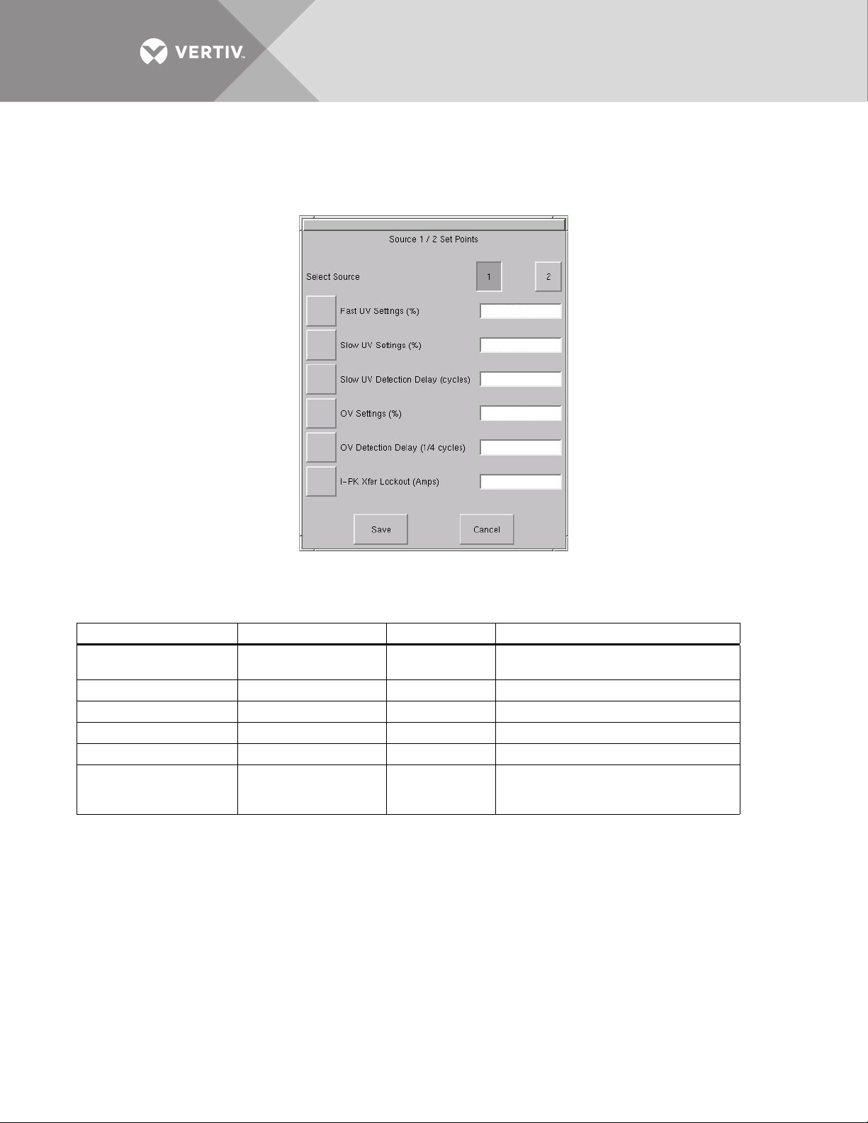
To configure the setpoints for each source:
1. Select SOURCE 1/2 Set Points from the User Settings dialog box.
The Source 1/2 Set Points dialog is displayed.
Figure 50 Source setpoints
2. Select 1 to configure the settings for Source 1.
3. Configure the settings using the keypad or dialog box that is displayed when you touch a button.
Table 10 Setpoint parameters
Button Range Default Comments
Fast UV Setting (%)
Slow UV Setting (%) -5 to -20% -10% Set in increments of 1%.
Slow UV detection delay 1-60 cycles 5 cycles Units: Line Cycle
OV Setting (%) +5% to +20% +10% Set in increments of 1%.
OV Detection Delay 1-255 cycles 3 cycles Units: 1/4 Line Cycle
I-PK Xfer Lockout
-10 to -30% of Nominal
voltage rating
0 – 3.0 multiplied by the
unit current rating.
-20% Set in increments of 1%.
1.5 * Unit Current
Rating
I-peak Xfer lockout detection point.
Units: Amps RMS. Select the HI or LO buttons
to configure your setting.
4. Select 2 for Source 2.
5. Configure the settings, as described in Step 3.
6. Select SAVE to keep the settings for both sources.
The Set Points dialog is closed and the User Settings dialog is displayed.
7. Select MANUAL MAX XFER PHASE ANGLE.
A keypad is displayed.
This setting configures the maximum allowed phase difference between the sources and applies to all manual transfers as
well as any auto retransfer.
a. Configure this setting with a range of ± 1-30 degrees.
The default setting is ±15 degrees and the resolution is 1 degree.
b. Select OK to save the setting.
The setting is now displayed in the adjacent field in the User Settings dialog box.
Vertiv™ | Liebert® STS2™ 100-1000A, 50/60Hz User Manual | Rev. 12 | 11/2017 88
Page 97

8. Select FREQUENCY TRIP POINT.
A keypad is displayed.
This choice verifies that the source is running at the proper frequency. This choice sets the frequency deviation in
the frequency that triggers the frequency trip point alarm. The frequency deviation setting is the allowable frequency
variation from nominal (60.0 or 50.0 Hz) before activating the frequency deviation alarm. The frequency setting
applies to both input sources.
a. Configure this setting with a range of 0.1 – 3.0 Hz
The default setting is 3 and the resolution is 0.1.
b. Select OK to save the setting.
9. Select RETRANSFER DELAY.
A keypad is displayed.
With the secondary source being used, this setting sets the length of time the switch waits until attempting to transfer
back to the preferred source.
a. Configure this setting with a range of 1 to 60 seconds.
The default setting is three (3) seconds and the resolution is 1 second.
b. Select OK to save the setting.
The setting is now displayed in the adjacent field in the User Settings dialog box.
10. Select AUDIO LEVEL.
A dialog box is displayed with HI and LO settings.
This choice sets the loudness of the horn or beeper that is sounded for audible alarms.
a. Configure this setting with a range of 1–10 (ten).
The default setting is 5. The settings have an increment of 1 (one).
b. Select OK to save the setting.
The setting is now displayed in the adjacent field in the User Settings dialog box.
You can select TEST to briefly sound the alarm to judge its volume.
11. Select DISPLAY BRIGHTNESS.
A dialog box is displayed with HI and LO settings.
This choice sets the brightness for the touchscreen.
a. Configure the Contrast and Brightness settings with a range of 1 – 10 (ten).
b. Select OK to save the settings.
12. Set the AUTO REXFER ENABLE choice.
The auto retransfer enable setting determines whether the switch automatically returns the preferred source after that
source is restored.
• Select YES to enable the automatic transfer.
• Select NO to disable the automatic transfer. The setting requires transfers be done manually.
13. Set the AUTO RESTART ENABLE choice.
This setting determines whether the Liebert STS2 can be started automatically when power is restored after it has been
lost.
• Select YES to enable the automatic restart.
• Select NO to disable the automatic restart. This settings requires a manual restart of the Liebert STS2.
14. Select a setting for the I-PEAK RESET.
• Select AUTO to configure the Liebert STS2 to automatically reset when a fault clears and the voltage and current are
normal.
• Select MAN to require a manual reset of the Liebert STS2 when fault clears and the voltage and current are normal.
• The default setting is Auto.
CAUTION
Risk of equipment damage and personnel injury.
Use of Auto Restart is site specific. Do not enable auto restart unless the infrastructure is designed for
unattended operation and there is no chance of equipment or personnel harm by automatic re-energizing
of the system.
Consult with your Vertiv site engineer as to whether Auto restart should be enabled.
Vertiv™ | Liebert® STS2™ 100-1000A, 50/60Hz User Manual | Rev. 12 | 11/2017 89
Page 98
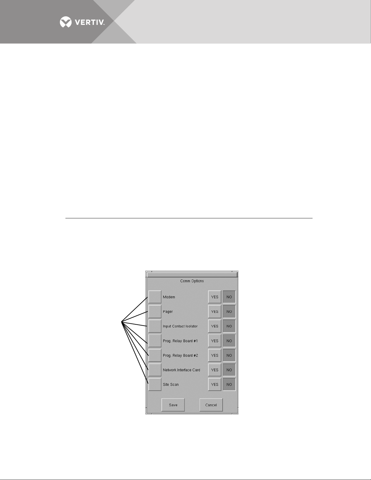
13.7.4 System Settings
Option
buttons
The System Settings choice under the Config menu displays another pop-up menu with three choices:
• Comm Options (see Section 13.8)
• System Options (see Section 13.9)
• System ID (see Section 13.10)
To access the System Settings menu:
1. Select CONFIG from the menu bar.
2. Select SYSTEM SETTINGS from the Config menu.
13.8 Comm Options
The Comm Options dialog box allows you to configure the communications settings for the Liebert STS2.
• Select COMM OPTIONS from the System Settings Menu. (If needed, see 13.7.4 - System Settings to access the System
Settings menu.)
The Comm Options dialog box is displayed. See Figure 51.
• An option can be enabled by selecting YES.
• An option can be disabled by selecting NO.
• An option can be configured by selecting the adjacent option button to display a separate configuration dialog box.
The instructions for configuring the communications options are provided in this section:
Option
Input Contact Isolator 13.8.1 - Configuring the Input Contact Isolator Settings
Prog. Relay Board 13.8.2 - Configuring the Programmable Relay Board Settings
Network Interface Card 13.8.3 - Configuring the Liebert IntelliSlot
Site Scan 13.8.4 - Liebert SiteScan
Figure 51 Comm options dialog box
®
Configuration
Refer to:
™
SNMP/Web/Modbus 485 Card
Vertiv™ | Liebert® STS2™ 100-1000A, 50/60Hz User Manual | Rev. 12 | 11/2017 90
Page 99
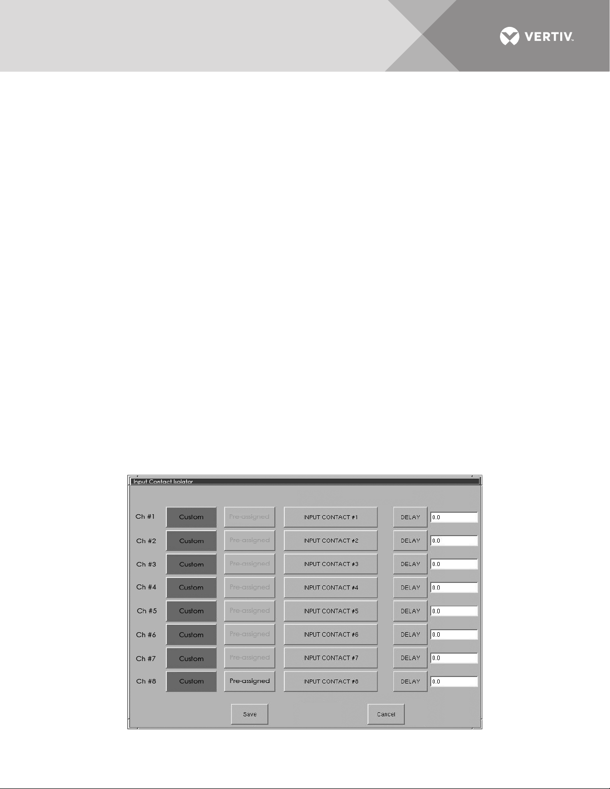
13.8.1 Configuring the Input Contact Isolator Settings
The Input Contact Isolator (ICI) is an optional, eight-channel input board for up to eight external user alarm or
message inputs to be routed to the Liebert STS2’s alarm network. If the Transfer Inhibit option is supplied, the ICI
will accommodate up to seven external user alarm or message inputs.
The contact is set to normally open. When a contact closes or opens, an event is triggered. See 6.4 - Input
Contact Isolator Board for more information on the ICI.
The Input Contact Isolator options are configured through the Input Contact Isolator dialog box, which is
accessed from the Comm Options dialog box. The Input Contact Isolator dialog box contains eight choices to
match the eight channel input board. You can label each button to identify the event associated with the contact.
When the dialog box is accessed, each button flashes to display the Input Contact Isolator number and the user
entered label. This label also appears in the Display Panel when an event related to an Input Isolator Connector is
triggered.
The Input Contact Isolator dialog box allows you to:
• Label the input contact assignments for your setup.
• Set the delay for an external event triggering an alarm.
• Review the isolator contact assignments, once the labels are entered.
The delay allows you to set the number of seconds which a condition needs to persist to trigger an alarm.
These input alarms can also be configured to activate a programmable relay output, which is discussed in
Configuring the Programmable Relay Board Settings on page 92.
When the Transfer Inhibit option is supplied, connect a N.O. dry contact (customer-supplied) to Input Contact 8
(Pins 15 and 16). When the customer contact closes, transfers will be inhibited as long as the contact remains
closed. Input Contact 8 is factory-set so no setup is required. The Transfer Inhibit option prevents Input Contact
8 from being used for any other input.
To configure the Input Contact Isolator relays:
1. Select INPUT CONTACT ISOLATOR from the Comm Options menu.
The Input Contact Isolator dialog box is displayed.
Figure 52 Input contact isolator dialog box
Vertiv™ | Liebert® STS2™ 100-1000A, 50/60Hz User Manual | Rev. 12 | 11/2017 91
Page 100

2. Select INPUT CONTACT 1.
A keyboard is displayed to allow you to enter the name of the alarm.
3. Enter the name of the alarm set for that input. For example, a fan problem could be indicated by naming the button FAN.
4. Select OK on the keyboard to keep your label.
5. Select DELAY.
A keypad is displayed prompting you for a delay time, in seconds, for a condition to exist before the alarm is triggered.
6. Enter the delay value. The range for the values are from 0 (zero) to 99.9 seconds.
7. Select OK on the keypad to keep your setting.
The value you entered is displayed in the field adjacent to the corresponding input contact.
8. Repeat steps 2 to 7 for each input contact.
9. Select SAVE after you have configured all input contacts.
Be sure to select Save even if you have accessed this dialog only to change a setting.
10. Enter the settings in Input Contact Isolator Settings Record on page 134.
This information is not saved if control power is removed.
11. Select OK in the Comm Options dialog box to activate the settings.
13.8.2 Configuring the Programmable Relay Board Settings
The Liebert STS2 can contain up to two Programmable Relay Boards (PRB) that can trigger an external device
when an event occurs in the Liebert STS2. For example, if Source 1 fails, an external light flashes.
See 6.1 - Programmable Relay Board for more information on the PRB’s.
The Programmable Relay Board dialog box with two options: STANDARD SET and USER DEFINED SET. The
STANDARD SET are the factory-configured settings.
The STANDARD SET for the Programmable Relay Board settings are:
Table 11 Standard settings for programmable relays
Relay Setting Definition
1 SOURCE 1 FAIL Source 1 failure.
2 SOURCE 2 FAIL Source 2 failure.
3 BYPASS CB4 CLOSED Switch (CB4) is closed, Source 1 is bypassed.
4 BYPASS CB5 CLOSED Switch (CB 5) is closed, Source 2 is bypassed.
5 TRANSFER INHIBIT A transfer between Source 1 and Source 2 is being restrained.
6 OUT OF SYNC
7EQUIP OVER TEMP
8 Blank No setting.
The phase difference between sources 1 and 2 exceeds the allowable
threshold for transfer,
The ambient temperature of the Liebert STS2
threshold for operation.
exceeds the recommended
The USER DEFINED SET allows you to assign faults and alarms to each contact on the relay boards.
Utilizing the USER DEFINED SET, you can also select Input Contact Isolators to associate with a programmable
relay.
In addition individual events, three other assignment choices are available:
• SELECT ALL sends a summary event to the selected relay whenever any event occurs. If this setting is selected for a relay,
no other event needs to be assigned for that relay.
• ON SOURCE 1 or ON SOURCE 2 can be assigned to a relay to send a notification when that source is being used by the load.
Once configured, the Liebert STS2 continuously checks the status of the items defined for each contact and
updates the state of the relay.
Vertiv™ | Liebert® STS2™ 100-1000A, 50/60Hz User Manual | Rev. 12 | 11/2017 92
 Loading...