

Vertiv LIEBERT PSI5 Series, LIEBERT PSI5-1500RT100, LIEBERT PSI5-3000RT100 Quick Installation User's Manual
LIEBERT PSI5™ UPS
Quick Installation User Guide
I M P O RTAN T: Before installing,
connecting to supply or operating
your Liebert PSI5TM UPS, please
review the Safety and Regulatory
Statements sheet. For detailed
installation, operating, maintenance
and troubleshooting information
refer to the PSI5TM User Guide
available at www.VertivCo.com.
INSTALLATIO N
1. Inspecting the UPS
Inspect the UPS for any signs of
obvious damage. If damage is
visible, do not proceed and call
our warranty support line for
assistance at 1-800-222-5877
menu option 3, or email at
microups.warranty@vertivco.com.
2. Choosing a location
Install the UPS in a
temperature-controlled
environment that is free of
corrosive and conductive
contaminants. Avoid locations
near heat or water sources and
exposed to direct sunlight. For
proper ventilation, leave four
inches clearance on all sides of
the UPS.
The input outlet should be
nearby and easily accessible.
3. Installing the UPS
The UPS and optional PSI5TM
UPS External Battery Cabinets
may be installed in either a
tower or rack configuration. For
tower installation, assemble and
attach the tower support stands.
For rack installation, attach the
brackets to the UPS, install the
rail kit in the rack if needed, and
install the UPS in the rack.
NOTE :
computer room as defined in the
standard for the protection of
electronic computer/data
processing equipment of ANSI/
NFPA 75.
This UPS is not for use in a
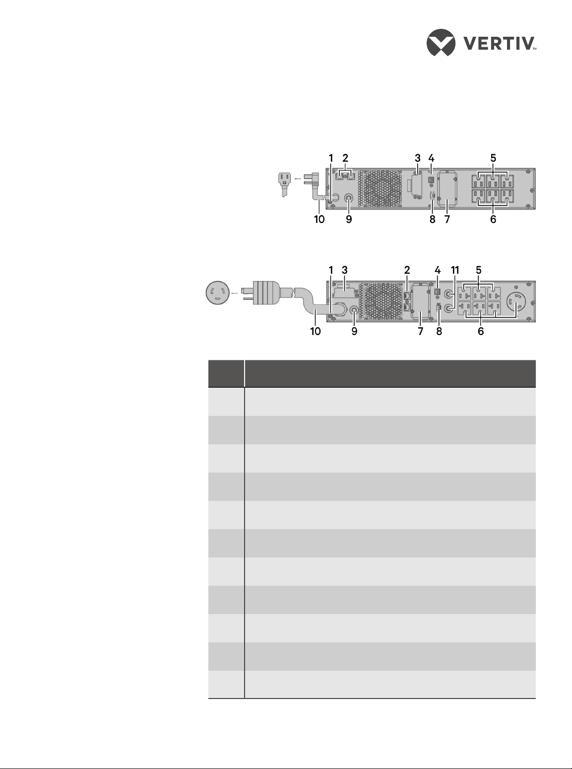
MODEL DESIGN CONFIGURATIONS
PSI5-1500RT100
PSI5-3000RT100
# Description
1 Grounding screw
2 Network/Fax/Modem surge protection input/output
3 External battery connector
4 USB communication port
5 Programmable receptacles
6 Non-programmable receptacles
7 SNMP IntelliSlot port
8 Emergency Power O (EPO) connector
9 Input circuit breaker
10 AC input
11 Output circuit breaker
590-2192-617A/SL-70358_REV0 1
LIEBERT PSI5™ UPS
Quick Installation User Guide
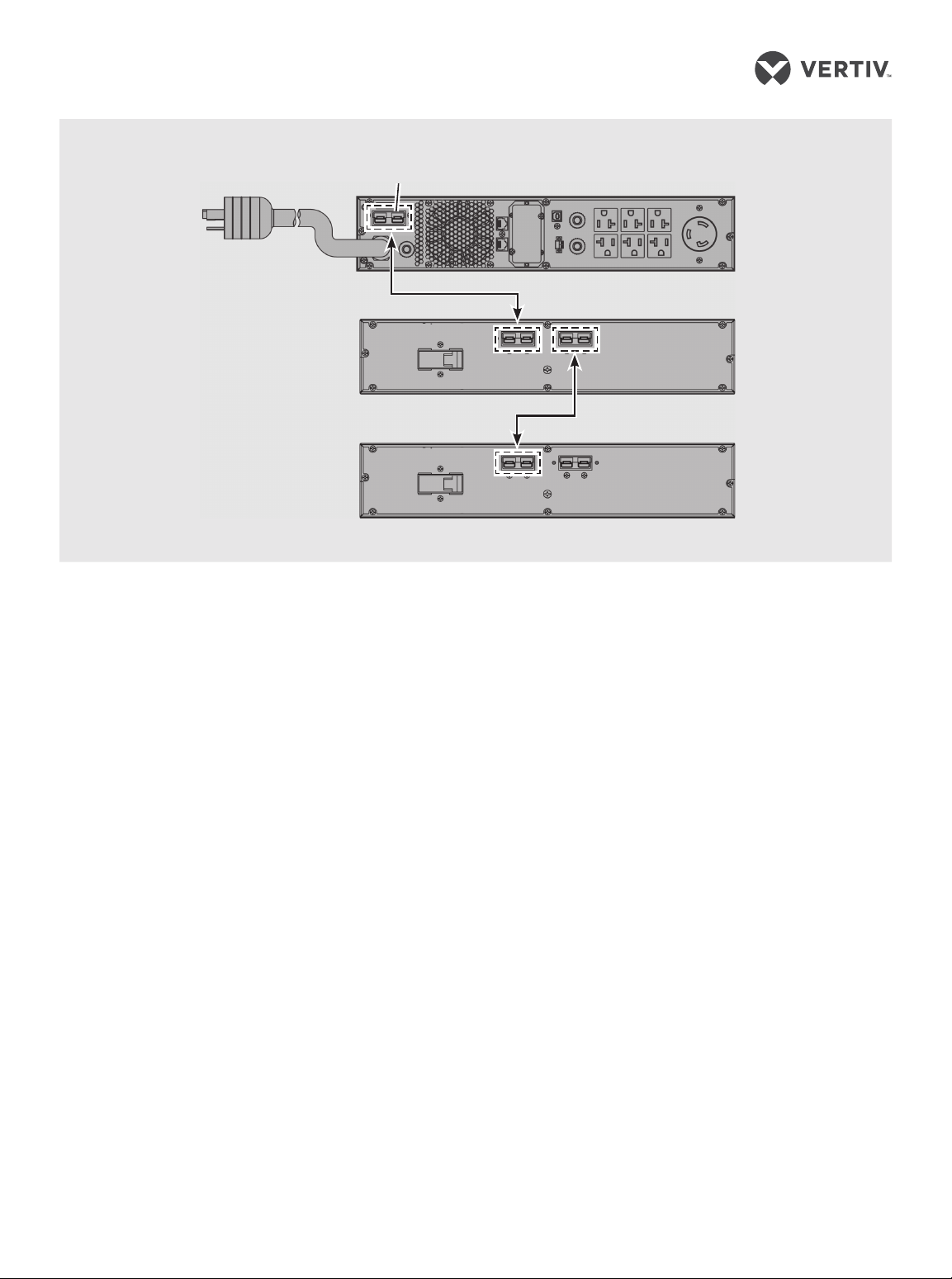
UPS to External Battery Cabinet Connections
PSI5-3000RT100
Shown
Single/First EBC
Second EBC
CONNECTIONS
1. Connecting Loads
The UPS has
non-programmable and
programmable rear outlets.
Plug your critical equipment
(such as computer, monitors,
etc.) into the non-programmable
outlets and
equipment (such as printers
and other less-often used
peripherals) into the
programmable outlets.
your less-critical
2. Connecting for Network
Protection (Optional)
Connect a network, fax, or
modem to the network/fax/
modem surge-protection ports
on the rear panel for protection
from electrical surges to your
computer or telephone
network.
3. USB Communication
Connection (Optional)
Connect the UPS through the
rear panel USB Type-B port to a
computer via USB to allow
unattended, controlledshutdown of your computer in
case of UPS input power failure.
EBC port
The UPS works with the
computer running software
built-in within the Microsoft®
Windows® operating system or
the Trellis™ Power Insight
software located at www.
VertivCo.com.
4. Emergency Powero (EPO) Connection
(Optional)
To comply with national and
local wiring codes and
regulations, the EPO connector
internally disconnects all power
sources to the UPS and
connected equipment. To use
this feature remove the factoryinstalled jumper on the rearpanel EPO connector and
connect to active-open
contacts that are normally
closed but open during an
emergency power o event.
Operating logic may be
reversed in the Settings menu.
If you do not use the EPO
connector, leave the factoryinstalled jumper in place and
the default (active open) EPO
setting in the Settings Menu.
5. External Battery Cabinet
Connection (Optional)
External battery cabinets
provide longer battery run-time
for connected devices. Refer to
PSI5TM User Guide, to select the
appropriate model and quantity
for your model and applications.
You can connect up to 6 battery
cabinets to the PSI5.
1. Turn o the UPS utility input.
2. Open the front left cover on
the UPS and the External
Battery Cabinet (EBC) and
disconnect the internal
batteries.
3. Remove the EBC terminal
covers from the UPS and the
EBC. Connect one end of
the external battery cable to
the UPS and one end to the
battery cabinet. If
connecting more than one
external battery, connect
one end of the external
battery cable to the second
connector on the battery
cabinet, then connect the
other end to the next battery
cabinet.
2 590-2192-617A/SL-70358_REV0

LIEBERT PSI5™ UPS
Quick Installation User Guide
4. Once the UPS and EBC(s)
are connected, secure the
connection with the screws,
reconnect the internal
batteries and replace the
front left covers on the
units.
5. After installation and initial
startup, set the number of
installed battery cabinets in
the UPS settings.
NOTE : When two or more external
battery cabinets are used with PSI5
model 3000, the
decreased by 20%.
UPS load rating is
6. Network communication
card connection
(optional)
For external status monitoring,
there is a network
communications port where
one of these network cards can
be installed:
• IntelliSlot Relay card,
IS-UNITY-SNMP
• IntelliSlot Unity card,
IS-UNITY-DP
1. Remove the two screws and
protective cover on the rearpanel network
communications port.
2. Insert the card into the port
and secure it with the
screws. Refer to the
documentation with the
card or at www.VertivCo.
com for cable connection
and operation.
7. Connecting AC Input
Ensure that all the loads are
first powered o. Connect to an
input-power supply/wall outlet
that is properly protected by a
circuit breaker in accordance
with national and local electrical
codes. The input receptacle
must be grounded Once the
UPS is plugged into the wall
outlet, it begins charging the
battery.
OPERATION
1. Starting up the UPS
Plug the UPS input plug into a
stable 120VAC source. The LCD
display briefly turns on and the
batteries begin charging. Press
and hold the ON/MUTE button
for two seconds until the
display flashes On. The UPS is
in Battery Self Test mode for 10
seconds. After a successful
battery self-test, the UPS is in
On Mode.
2. Shutting down the UPS
Press and hold the OFF/ENTER
button for two seconds, turning
the battery-backed-up outlets
o. Disconnect the input power.
3. Fully shutting down
the UPS
Perform the normal shutdown
sequence. Remove the front
bezel, then disconnect the
battery connector. Replace the
front bezel. The unit is now fully
shut down.
MAINTENANCE AND
BATTERY REPLACEMENT
Precaution
Although the UPS is designed and
manufactured to ensure personal
safety, improper use can result in
electrical shock or fire. To ensure
safety, observe the following
precautions:
• Turn o and unplug the UPS
before cleaning it.
• Clean the UPS with a dry cloth.
Do not use liquid or aerosol
cleaners.
• Never block or insert any
objects into the UPS ventilation
holes or openings.
• Do not place the UPS power
cord where it might be
damaged.
Battery Charging
The batteries are valve-regulated,
non-spillable, lead acid and should
be kept charged to attain their
design life. The UPS charges the
batteries continuously when it is
connected to the utility input
power. If the UPS will be stored for
a long time, we recommend
connecting the UPS to input power
for at least 24 hours every four to
six months to ensure full recharge
of the batteries.
Replacing the Battery
I M P O RTAN T: Before you proceed,
please review the battery safety
precautions available at https://
www.vertivco.com/
ComplianceRegulatoryInfo.
You may safely replace the internal
battery pack. See the Specifications
in the User Guide online at www.
VertivCo.com for the part number
of the replacement battery for your
UPS model number.
NOTE : Replace the battery with
the same type and number
asoriginally installed.
1. Removing the front panel
Remove the front bezel by
pulling firmly until the snaps
release.
2. Disconnecting the
battery wires
Disconnect the battery
connector by squeezing the
ends and pulling apart.
3. Removing the battery box
Remove the two screws and the
metal battery cover plate. Slide
out the existing battery kit and
disconnect the battery
terminals from the connector,
disconnecting the red wire first
then the black wire.
590-2192-617A/SL-70358_REV0 3
 Loading...